Next Section | Table of Contents
doi:10.2204/iodp.pr.312.2006
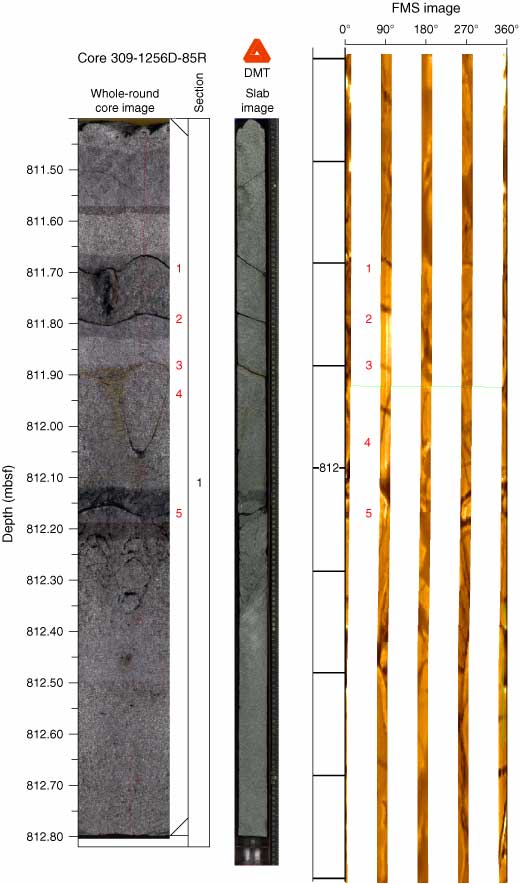
Figure F66. An example of a whole-round image (left) and matching slab image. Fractures appear as sinusoids in the whole-round image and lines in the slab image. Preliminary Formation MicroScanner (FMS) image (right) has been depth-shifted <10 cm to align fractures with the core images. Red numbers adjacent to the whole-round image and within the FMS image identify matching fractures.