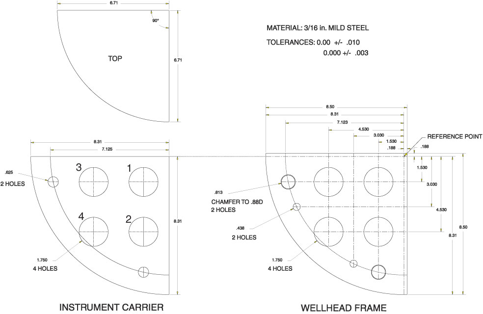
Figure F16 (continued). F. Drawing of mounting pattern for up to four hydraulic coupler pins on base plate of instrument carrier (ordering shown as viewed from above; screen numbers ordered from bottom to top), and for up to four coupler sockets on base plate of wellhead frame. Pairs of intermediate sized holes on instrument carrier base plate hold alignment pins that fit into corresponding holes in wellhead frame base plate, serving as an initial guide for entry of the hydraulic coupler pins into the sockets.
Previous | Close | Next | Top of page