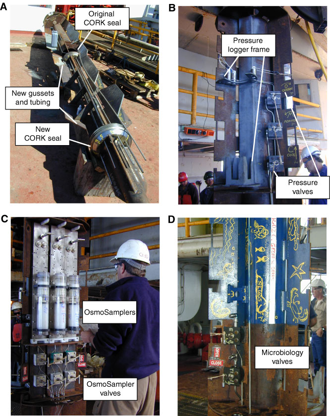
Figure F19. Photos of CORK head for system deployed in Hole U1301B. A. CORK body on deck prior to deployment, after modifications to extend the height of the CORK head. This was accomplished by welding a short piece of 4½ inch casing below the original CORK seal, attaching a new seal, and adding gussets along the extended section for stability. B. Pressure bay showing location of logger frame and valves used to control access to pressure lines. C. Fluid sampling bay with three CORK head OsmoSampling systems attached. All values are open for deployment. D. Microbiology and auxiliary sampling bay showing sampling valves held open during deployment with rubber bands attached to the packer inflation line.
Previous | Close | Next | Top of page