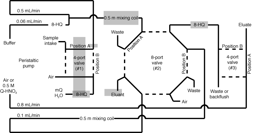
Figure F1. Schematic diagram of the apparatus used for extraction of trace elements from fluid samples by immobilization onto 8-hydroxyquinoline columns (shown as 8-HQ). The pumping direction is from left to right and the calibrated flow rates are shown for each peristaltic pump tubing line. Switching of the valves was controlled by a graphic user interface software program to cycle the system through the entire extraction process after placing the sample in the uptake slot. Solution compositions are provided in the text. mQ = 18.2 MΩ water.

Close | Next | Top of page