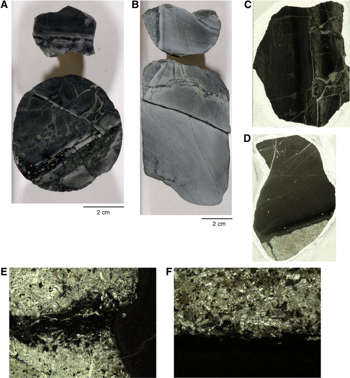
Figure F272. Dike margin features as observed in close-up photographs (A, B), whole thin sections (C, D), and photomicrographs (E, F) in intervals (A, C) 312-1256D-176R-2, 0–10 cm, and (B, D, E, F) 175R-1, 44–53 cm. A. Brecciated, hydrothermally altered dike boundary (wet) (interval 312-1256D-176R-2, 0–10 cm). B. Fracture network in a chilled margin where a dike has been intruded into fine-grained dolerite (wet) (interval 312-1256D-175R-1, 44–53 cm). C. More detail of the brecciated, hydrothermally altered dike boundary (Thin Section 13; Sample 312-1256D-176R-2, 0–2 cm; 1277.60 mbsf) (plane-polarized light; field of view [FOV] = 2.5 cm). D. Fracture network through a hydrothermally altered chilled margin (Thin Section 7; Sample 312-1256D-175R-1, 43–46 cm; 1271.73 mbsf) (plane-polarized light; FOV = 4 cm). E. Magnetite (+ minor chlorite) vein with adjacent chlorite-rich alteration halo, all truncated by a fine-grained dike margin (Thin Section 7; Sample 312-1256D-175R-1, 43–46 cm; 1271.73 mbsf) (plane-polarized light; FOV = 4.5 mm). F. Pyrite + minor magnetite vein lining a dike margin (Thin Section 7; Sample 312-1256D-175R-1, 43–46 cm; 1271.73 mbsf) (plane-polarized light; FOV = 4.5 mm).
Previous | Close | Next | Top of page