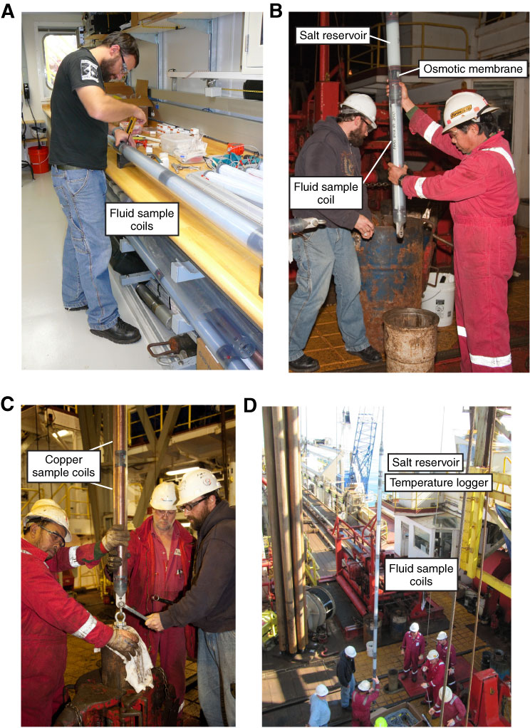
Figure F11. Photographs of downhole OsmoSampler systems. A. OsmoSampler being assembled in laboratory prior to deployment. Several fluid sample coils (PTFE) are being configured in series with a single osmotic pump. Additional OsmoSamplers are visible in the rack below the bench. B. OsmoSampler being deployed on the rig floor. Salt reservoir is visible near top of photograph, with osmotic membrane separating the saturated salt solution from distilled water fluid reservoir in sample coil. C. Two copper tubing sections being deployed as part of a gas-tight OsmoSampler. D. OsmoSampler being deployed on rig floor showing salt reservoir and osmotic membrane at top, PVC holder with temperature logger, and four PTFE sample coils configured in series. The salt reservoir for the next (deeper) OsmoSampler is visible at the bottom of the suspended instrument string.
Previous | Close | Next | Top of page