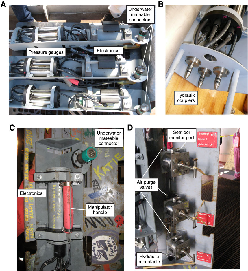
Figure F8. Photographs of pressure logging systems. A. Three sets of CORK pressure logging systems prepared for Expedition 327. Electronics components are built into frames that are subsequently attached in one of three CORK wellhead bays. Pressure logging systems comprise (right to lift in photograph; top to bottom when deployed): underwater mateable connector (Teledyne ODI, covered with cap in photograph), pressure case containing electronics and batteries, underwater connectors and cables, and pressure gauges (Paroscientific). B. Pressure gauges are connected with ![]() inch stainless steel tubes to hydraulic couplers that fit into receptacles attached to the wellhead, located below the pressure logger frame. C. Pressure logger and gauge frame houses pressure case (containing electronics) and underwater mateable connector. Frame slides into rack welded to wellhead, which also aligns hydraulic couplers as they slide into receptacles. D. Pressure lines running from depth reach a high point just below screw-cap air-bleed valves before passing through three-way valves in wellhead. Rotation 180° counterclockwise opens pressure gauges to monitor seafloor conditions, whereas rotation 180° clockwise has pressure gauges monitoring conditions within interval at depth below seafloor. Short pieces of stainless steel rod are welded onto valve handles to show which side of valve is open.
inch stainless steel tubes to hydraulic couplers that fit into receptacles attached to the wellhead, located below the pressure logger frame. C. Pressure logger and gauge frame houses pressure case (containing electronics) and underwater mateable connector. Frame slides into rack welded to wellhead, which also aligns hydraulic couplers as they slide into receptacles. D. Pressure lines running from depth reach a high point just below screw-cap air-bleed valves before passing through three-way valves in wellhead. Rotation 180° counterclockwise opens pressure gauges to monitor seafloor conditions, whereas rotation 180° clockwise has pressure gauges monitoring conditions within interval at depth below seafloor. Short pieces of stainless steel rod are welded onto valve handles to show which side of valve is open.
Previous | Close | Next | Top of page