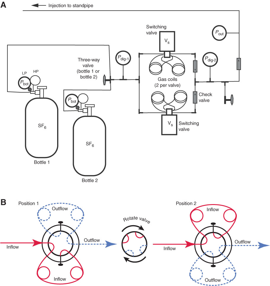
Figure F4. Diagrams of the SF6 tracer injection manifold and switching valves. A. Manifold. SF6 was introduced from two bottles (one at a time) containing the tracer in liquid form at ~320 psi. A two-stage regulator on each bottle was used to adjust the gas pressure relative to that in the standpipe upstream of the mud pumps (Fig. F3). Eight-port switching valves were used to inject fixed quantities of SF6 gas at 30 s intervals. Check valves prevented backflow of standpipe fluid into the tracer injection manifold. Pbot = analog pressure at outlet to two-stage regulator on SF6 tracer bottle. LP = low pressure, HP = high pressure. Pdig-1 and Pdig-2 = digital pressure gauges used to monitoring pressure upstream and downstream from the switching valves, respectively. Vs = switching valve. Pout = analog gauge used to monitor pressure at the standpipe. B. Switching valves alternate flow of gas between two ~20 mL coils of stainless steel tubing. In one position, one coil empties while the other coil fills. When the valve switches, the previously filled coil empties while the empty one fills. Two valves were run in parallel during the SF6 injection experiment, delivering the contents of four coils/min, as described in the text.
Previous | Close | Next | Top of page