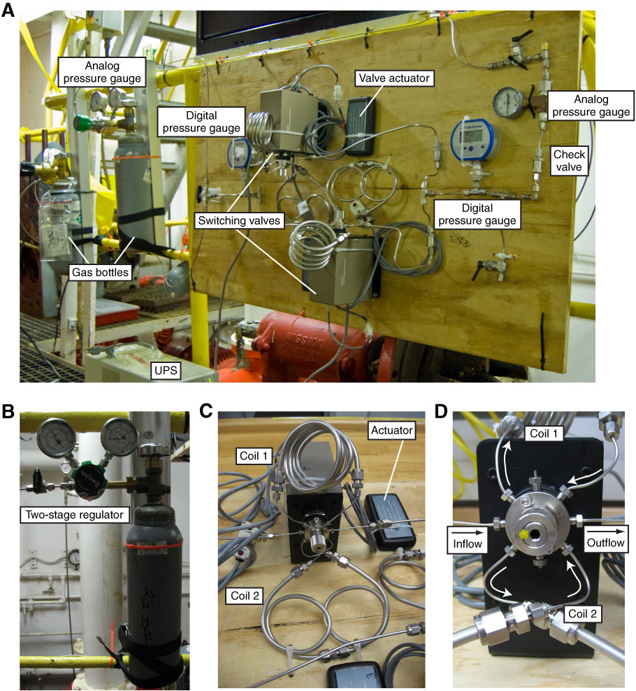
Figure F6. Photographs of SF6 injection manifold and components as deployed during Expedition 327. A. Tracer gas bottles, regulators, and injection manifold mounted on rail in mud pump room. Gas entered manifold on the left and exited on the right. Gas exiting manifold was directed through ⅛ inch stainless steel line to an inlet port on standpipe located behind manifold. This standpipe is pressurized with a positive displacement pump (generally to ~42 psi) and fed into the primary shipboard mud pump system. UPS = uninterruptable power supply. B. SF6 bottle in use during experiment. Each bottle contained ~1 kg of SF6 in liquid form at ~320 psi, with outlet pressure from the bottles determined during the experiment using two-stage regulators. Pressure was adjusted to achieve desired differential pressure between the regulator (inlet) and standpipe pressure (outlet). C. Switching valve, actuator, and two gas coils (made from ¼ inch stainless steel tubing). D. Detail of switching valve showing ![]() inch inlet lines and gas flow direction through tubing and coils (arrows).
inch inlet lines and gas flow direction through tubing and coils (arrows).
Previous | Close | Next | Top of page