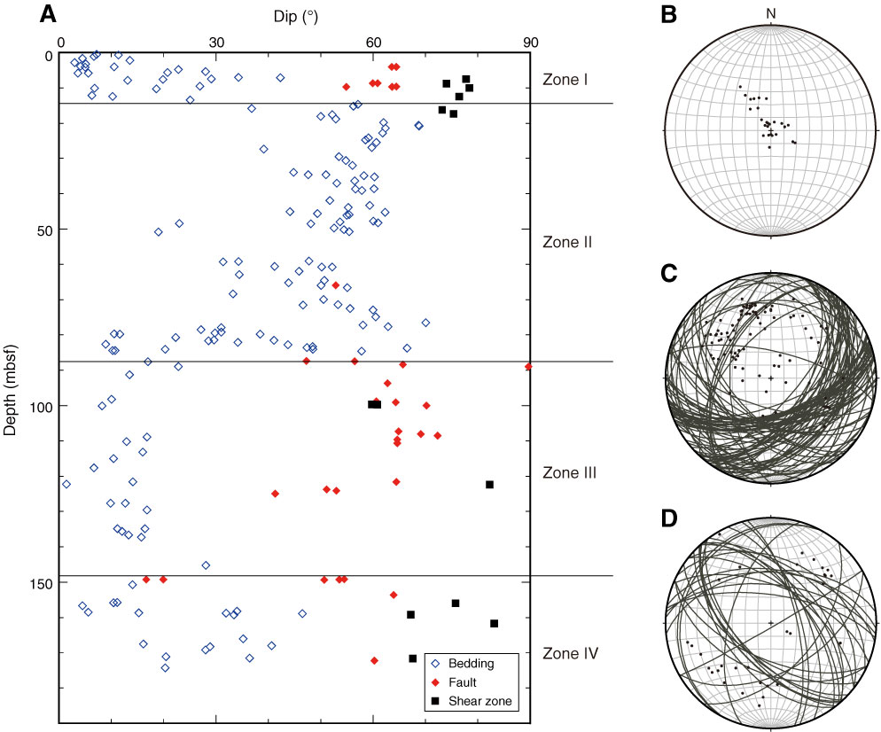
Figure F15. A. Distribution of bedding dip angles and deformation structures with depth, Holes C0012C and C0012D. Lines = boundaries between four zones defined based on dipping angle distribution. B. Equal-area stereographic projection (lower hemisphere) of bedding plane poles above 15 mbsf (Zone 1). C. Equal-area stereographic projection (lower hemisphere) of bedding planes and poles between 15 and 85 mbsf (Zone 2). D. Equal-area stereographic projection (lower hemisphere) of fault planes and poles (all zones).
Previous | Close | Next | Top of page