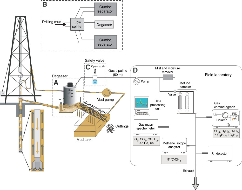
Figure F21. Diagram of the mud extraction system and the setup in the mud-gas monitoring laboratory (modified from Saffer, McNeill, Byrne, Araki, Toczko, Eguchi, Takahashi, and the Expedition 319 Scientists, 2010). A. The degasser used to separate drilling mud and dissolved gas is installed at the point where drilling mud is first exposed to the air. Dissolved gas is extracted from the fluid phase by pumping from the laboratory. B. A fraction of the drilling mud passes the flow splitter and bypasses the Gumbo separator. C. A safety valve is installed to compensate the pressure difference between pumping in the laboratory and gas pressure in the degasser. It also prevents the overflow of drilling mud into the gas monitoring system. D. Gas is filtered and dried upon arrival at the laboratory. An Isotube sampling system can collect gas samples before or after the gas dryer. A gas chromatograph, quadrupole mass spectrometer, Rn detector, and methane carbon isotope analyzer are connected to the pipeline and perform real-time monitoring of gas composition and methane carbon isotope. FID = flame ionization detector.

Previous | Close | Next | Top of page