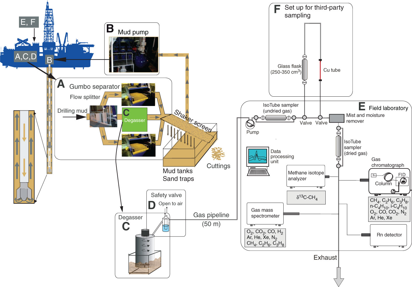
Figure F16. Diagram of mud extraction system, third-party sampling tools, mud-gas monitoring laboratory (modified from Expedition 319 Scientists, 2010b, and Expedition 337 Scientists, 2013), Expedition 338. A. Drilling mud is directed into a flow splitter, where mud flow is split into either the Gumbo separators or the degasser. Afterward, mud and cuttings are divided by a shaker screen. B. The remaining mud is transferred to mud tanks via sand traps and can be pumped down again. C. The degasser that separates drilling mud and dissolved gas is installed directly behind the flow splitter, where drilling mud is exposed to air for the first time. Extracted gas is transferred to the mud-gas monitoring laboratory. D. A safety valve regulates gas pressure and protects the gas monitoring system from overflowing mud. E. Gas is directed through an IsoTube sampling system to the dehydration module or first to a (F) third-party sampling line, which consisted here of glass flasks and copper tubes. After the gas is dried and cleaned, another IsoTube sampling system can collect gas samples for later analyses; a GC with flame ionization detector (FID), quadruple mass spectrometer, radon detector, and MCIA are connected to the pipeline to allow real-time monitoring of gas and methane carbon isotope composition.
Previous | Close | Next | Top of page