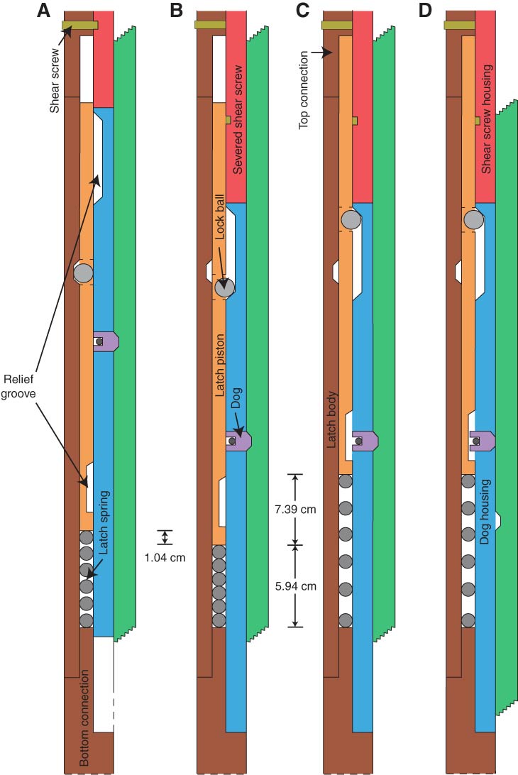
Figure F22. Diagrams of the Motion Decoupled Hydraulic Delivery System latch mechanism, Site U1402. A. After the latch is locked, the shear screws, lock balls, and dogs hold the shear screw housing, latch piston, and inner barrel subassembly (IBS), respectively, in place. B. Once the drill string is pressurized, the shear screws fail, allowing the shear screw housing and dog housing to shift downward, aligning the lock ball with the unlocked relief groove and completely compressing the spring. At this point, the latch is mechanically free to shift vertically but is unable to do so because of the drill string pressure. C. After the drill string pressure is completely bled off, the latch piston is driven upward by the latch spring, aligning the dog with the dog relief groove. D. At this point the IBS is free to descend, although friction between dogs and the dog body (of the IBS) may keep it from doing so until the drill string is repressurized. Not all components drawn to scale.

Previous | Close | Next | Top of page