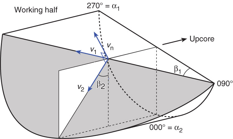
Figure F10. Diagram showing calculation of plane orientation (shaded) from two apparent dips. Intersections of split core surface, section perpendicular to split core surface, and section parallel to core direction with plane of interest are shown. (α1, β1) and (α2, β2) are the azimuths and dips of traces of the plane on two sections, respectively; v1 and v2 are unit vectors parallel to traces of the plane on two sections; and vn is the unit vector normal to plane.
Previous | Close | Next | Top of page