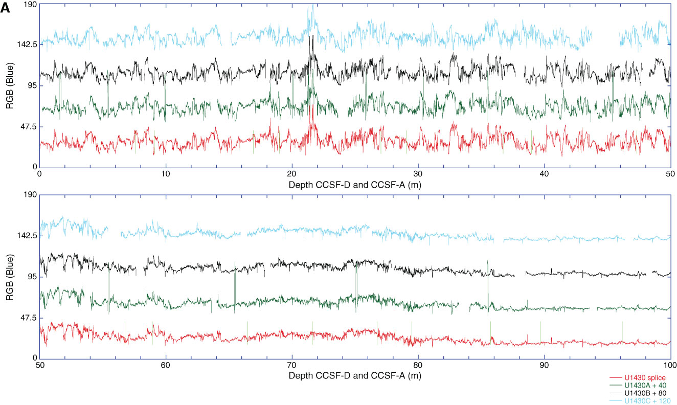
Figure F53. Composited cores and splice for Site U1430. Each core is adjusted (in depth) by a constant amount to align it with adjacent cores at a chosen tie point (typically a distinctive feature in all of the data sets). Other features may or may not align among adjacent cores because of differential squeezing and stretching during the coring process or because of variable expansion characteristics. The splice is constructed from the composited cores by selecting intervals from different holes such that coring gaps and drilling disturbances are avoided. Data included in the splice are plotted on the CCSF-D scale, whereas data not included in the splice are plotted on the CCSF-A scale. Horizontal light green lines indicate tie points where the splice changes from one hole to another. Only the splice is plotted on the correct y-axis scale; data from the Holes U1430A, U1430B, and U1430C are offset by 40, 80, or 120 units, respectively, for illustrative purposes. One and two point spikes are artifacts generated when the track sensor measures beyond the end of the ~150 cm sections. A. 0–100 m CCSF-A. (Continued on next two pages.)
Previous | Close | Next | Top of page