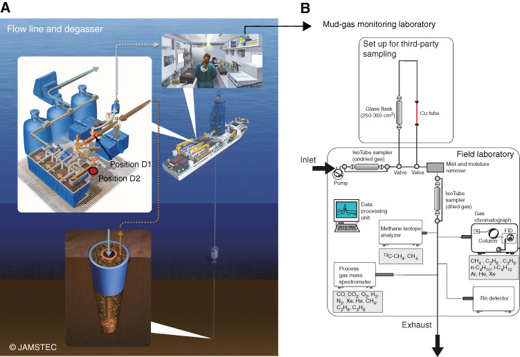
Figure F16. Mud extraction system, third-party sampling tools, and mud-gas monitoring laboratory (modified from Expedition 319 Scientists, 2010b; Expedition 337 Scientists, 2013; Strasser et al., 2014a). A. The gas-enriched drilling mud is transported upward and enters the main mud flow line, where it passes a flow splitter. One flow branch leads to a degasser, where the gas is extracted and forwarded to a mud gas monitoring laboratory (position D1). The position of the degasser was changed during the cruise; thus, for the depth interval from 2330 to 3058 mbsf, the degasser was in the mud trough (position D2). The mud is then forwarded to the shaker screens, where cuttings are removed. This is followed by transport of the drilling mud to and storage in mud tanks, where it can be pumped down again. B. After degassing, the gas is directed through an IsoTube sampling system to the dehydration module through a third-party sampling line, which consisted of glass flasks and copper tubes. After the gas is dried and cleaned, another IsoTube sampling system can collect gas samples for later analyses; a gas chromatograph with flame ionization detector (FID), quadropole mass spectrometer, radon detector, and methane carbon isotope analyzer are connected to the pipeline to permit real-time monitoring of gas and methane carbon isotope composition.
Previous | Close | Next | Top of page