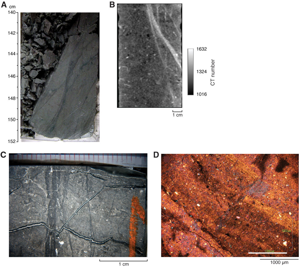
Figure F12. Shear zone structures. A. Anastomosing normal shear zone (Section 315-C0001H-11R-6). B. Shear zone seen in CT scan. C. Photomicrograph of slab section of an anastomosing normal shear zone (interval 315-C0001H-12R-3, 75–102 cm). D. Same as C (cross-polarized light with compensation). Clays are preferentially oriented subparallel to shear zone walls. Note coarser and darker infill compared with wall rock.
Previous | Close | Next | Top of page