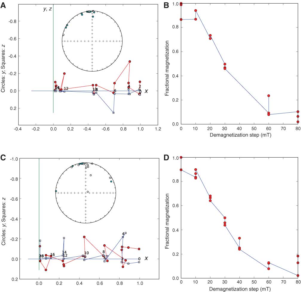
Figure F14. Example of behavior of specimen during AF demagnetization using the (A, B) inline AF demagnetizer and (C, D) Dtech D2000 AF demagnetizer during Expedition 318. A, C. Vector endpoint diagram of demagnetization of test specimen after imparting an ARM along the x-axis. Demagnetization steps are 0:0, 1:10, 2:20, 3:30, 4:40, 5:60, and 6:80 mT. Circles = projections into the x- and y-plane, squares = projections into the x- and z-plane. The specimen had been given an ARM along the z-direction. Inset is equal-area projection of directions at each measurement step. Open symbols are in the lower hemisphere; closed are in the lower hemisphere. B, D. Decay of remanence during demagnetization. For detailed explanation, see Tauxe (2010).
Previous | Close | Next | Top of page