Previous | Close | Next
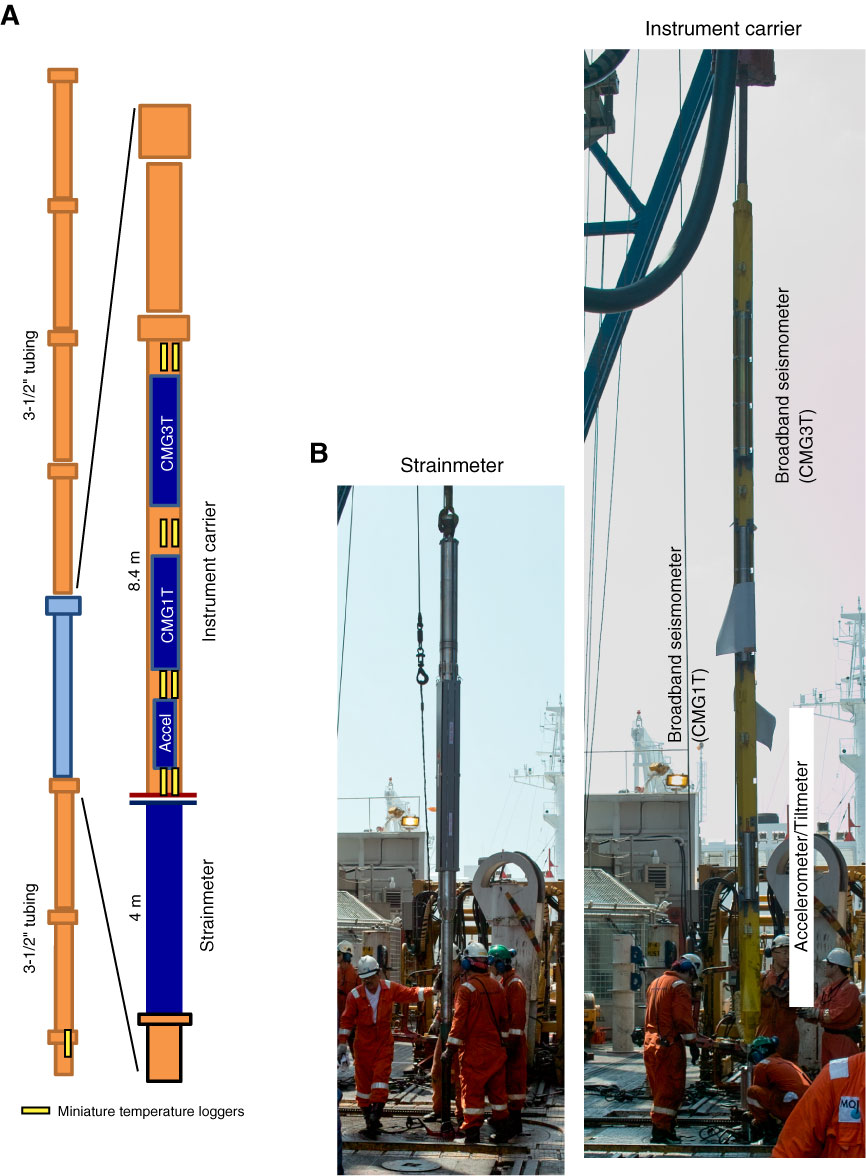
Figure F12. A. Schematic diagram showing dummy run test sensor tree instrument configuration. B. Photos of the dummy run assembly on the rig floor. (Continued on next two pages.)
Previous | Close | Next | Top of page