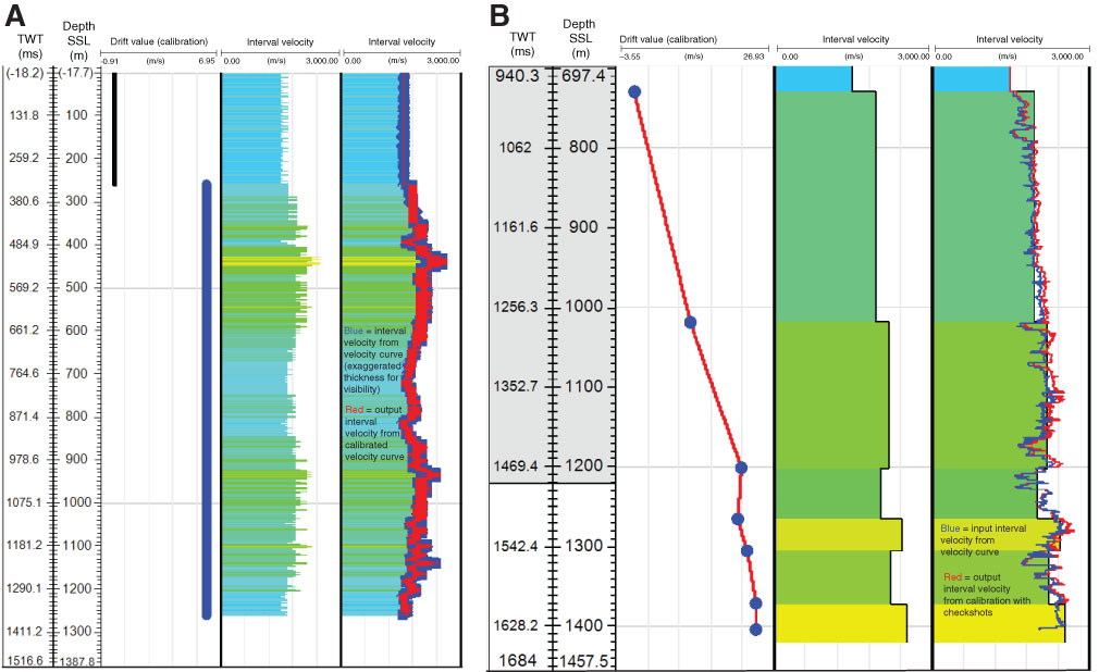
Figure F10. A. Initial interval velocity from the sonic compressional wave velocity data, Site U1420. First panel shows drift value for calibrating. Second panel shows the interval velocity from the constructed velocity curve, and third panel shows the results of calibration. The primary role of calibration in this instance is to initially match the seafloor between the velocity curve and interval velocity model and to create a 5 m sampling interval for the interval velocity. Note also that the upper interval to the seafloor is a constant velocity in the output interval velocity. TWT = two-way traveltime. B. First panel shows drift curve for sonic and VSP calibration for Site U1421. Second panel shows interval velocity from VSP check shots and seafloor constraints. Third panel shows the interval velocity for the original sonic log and the calibrated sonic log after adjusting with the drift value. The seismic depth scale below sea level (SSL) is derived from the TDR by using the logging seafloor depth and combined WMSF/CCSF/CSF scales.
Previous | Close | Next | Top of page