S.J. Gallagher, C.S. Fulthorpe, K. Bogus, and the Expedition 356 Scientists
Proceedings of the International Ocean Discovery Program Volume 356
publications.iodp.org
doi:10.14379/iodp.proc.356.106.2017

Site U14611
S.J. Gallagher, C.S. Fulthorpe, K. Bogus, G. Auer, S. Baranwal, I.S. Castañeda, B.A. Christensen, D. De Vleeschouwer, D.R. Franco, J. Groeneveld, M. Gurnis, C. Haller, Y. He, J. Henderiks, T. Himmler, T. Ishiwa, H. Iwatani, R.S. Jatiningrum, M.A. Kominz, C.A. Korpanty, E.Y. Lee, E. Levin, B.L. Mamo, H.V. McGregor, C.M. McHugh, B.F. Petrick, D.C. Potts, A. Rastegar Lari, W. Renema, L. Reuning, H. Takayanagi, and W. Zhang2
Keywords: International Ocean Discovery Program, IODP, Expedition 356, JOIDES Resolution, Site U1461, Northern Carnarvon Basin, Indonesian Throughflow, Miocene, Pliocene, Pleistocene, Australian monsoon, subsidence, aridity, reefs, ooids, tropical carbonates, Delambre Formation
MS 356-106: Published 26 February 2017
Background and objectives
International Ocean Discovery Program (IODP) Site U1461 is 100 km northwest of Barrow Island in the Northern Carnarvon Basin, ~150 m from the West Tryal Rocks-2 industry well (Figure F1). Site U1461 is on the shelf edge of an outer ramp (James et al., 2004). The seabed in the region is poorly sorted carbonate-rich (>90%) sediment made up of bioclastic gravel, sand, and mud (Jones, 1973; James et al., 2004). Coring at Site U1461 targeted a 1 km thick outer shelf to upper slope carbonate wedge that onlaps (because of basin-wide subsidence) a regional top Miocene surface (Figures F2, F3).
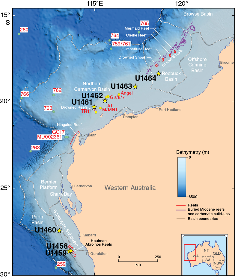
Figure F1. Map of the northwest shelf showing major basins and location of modern and “fossil” reefs.

Figure F2. Bathymetric map showing the seafloor around Sites U1461 and U1462.
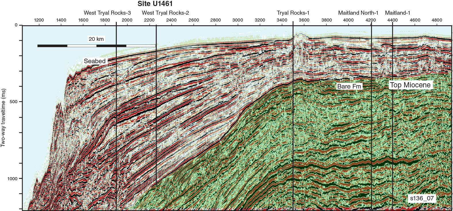
Figure F3. Multichannel seismic profile across Site U1461.
The primary objective of Site U1461 was to obtain a >4 My orbital-scale record of climate variability and monsoonal history comparable in resolution to other global climate proxy records. Most such records are from the deep ocean basins. However, one benefit of coring this shelf-margin setting is that terrigenous clay and terrestrial palynomorphs should be abundant, delivered by fluvial outflow during the rainy season (van der Kaars and De Deckker, 2003). This location is also close to the southernmost limit of the influence of the Australian monsoon and can be used to chart its latitudinal variability. Marine microfossil paleoproductivity analyses at this site should also reveal the dominance of the West Australian Current over the Leeuwin Current during glacial periods (cf. Spooner et al., 2011), when the Australian monsoon is thought to have been weak (Gallagher et al., 2014). Some intervals in this section consist of plankton ooze deposited at upper to middle slope paleodepths (Gallagher et al., 2009). Therefore, combining C/O and Mg/Ca analyses of microfossils from Site U1461 should produce a Pliocene–Pleistocene obliquity- (or even precession-) scale record that can be directly compared and correlated to the LR2004 stack (Lisiecki and Raymo, 2005) for chronostratigraphic and paleoceanographic analyses. Site U1461 is downdip from a drowned reef on a paleoshelf edge (Gallagher et al., 2014). By dating the reflectors and correlating these updip, it should be possible to constrain the age of onset of this reef and other reefs at this level regionally. Furthermore, downslope-transported reefal or shelf detritus into this section will enable analysis of reef and ramp development in response to variable sea level.
Operations
Transit to Site U1461
After a 469 nmi transit averaging 11.1 kt, the vessel arrived at Site U1461 at 1407 h (UTC + 8 h) on 17 August 2015. Shortly after arrival, a seafloor positioning beacon was deployed.
Site U1461
Site U1461 consisted of four holes (Tables T1, T2) with the objectives to recover a complete stratigraphy of the upper sedimentary section and material deeper than 1000 m drilling depth below seafloor (DSF). The first hole (U1461A) was cored to half-length advanced piston corer (HLAPC) refusal (284.7 m DSF). A single hard layer was encountered at ~54 m DSF, so an extended core barrel (XCB) was dropped and 2.5 m was cored with that system. Based on the results from Hole U1461A, a coring plan for Hole U1461B utilizing both piston and XCB coring was prepared to minimize recovery gaps. Hole U1461B was successfully piston cored to 375.2 m DSF. All advanced piston corer (APC) cores were oriented. The XCB coring system was then deployed, and coring continued to a final depth of 879.2 m DSF with good recovery. Coring was terminated after the XCB cutting time per core exceeded ~90 min. The third hole (U1461C) was used to fill in remaining recovery gaps in the upper sedimentary section to aid stratigraphic correlation and to try to deepen piston coring to recover gaps in recovery from the XCB system used in Hole U1461B. The hole was successfully piston cored to 443.9 m DSF with one 3 m interval drilled without coring to aid correlation. Four in situ temperature measurements were taken and all APC cores (356-U1461C-2H through 23H) were oriented. Hole U1461D was cored with the rotary core barrel (RCB) system to achieve the deep objective of the site. Hole U1461D was first drilled without coring to 455.0 m DSF with a center bit installed. The center bit was pulled and spot coring with the RCB system was accomplished from 455.0 to 474.4 m DSF. The center bit was again deployed and the hole was deepened by drilling without coring to 503.0 m DSF. At that depth, a single 9.7 m core was cut and then drilling continued to 565.0 m DSF. At that depth, continuous RCB coring began and continued to a final depth of 1095.3 m DSF. After the completion of coring, the hole was conditioned for logging and the upper ~500 m was displaced with heavy mud. Two separate logging tool strings were deployed. The triple combination (combo) tool string reached ~1030 m wireline log depth below seafloor (WSF). While logging up from depth, indications of a hole collapse were suspected through excess tension on the wireline. The Formation MicroScanner (FMS)-sonic tool string was assembled and deployed but only reached a total depth of ~190 m WSF before encountering a bridge. After several attempts to pass the bridge, an up pass to the end of the pipe was accomplished before logging was terminated and preparations were made to proceed to the next site.
Table T1. Operations summary, Site U1461. Download table in .csv format.
Table T2. Site U1461 core summary. Download table in .csv format. View PDF table.
A total of 301 cores were recorded for the site. The APC system cored 636.9 m with 654.18 m of core recovered (recovery = 102.7%). The HLAPC system cored 455.0 m with 464.99 m recovered (recovery = 102.2%). The XCB system cored 512.9 m with 360.19 m of core recovered (recovery = 70.2%). The RCB system cored 559.4 m with 325.51 m of core recovered (recovery = 58.2%). The overall recovery for Site U1461 was 83.4%. The total time spent on Site U1461 was 294.75 h (12.3 days).
Hole U1461A
After offsetting the vessel from the seafloor positioning beacon, drill floor activities commenced in preparation for Hole U1461A (20°12.8634′S, 115°3.9495′E). Given previous difficulty with the mudline core at Site U1459 (broken core barrel), we decided to tag the seafloor with the bit. A nonmagnetic HLAPC core barrel was dressed with a core liner in preparation for spudding Hole U1461A. The first attempt to establish the mudline resulted in a water core and the depth of the bit was subsequently adjusted; Hole U1461A was started at 1825 h on 17 August 2015. Based on the recovery of the mudline core, the seafloor depth was calculated to be 127.2 meters below sea level (mbsl). Cores 356-U1461A-1F through 3F were recovered with the HLAPC system before we changed to the APC system. Cores 4H through 8H were recovered; a hard layer was encountered at ~54 m DSF, and we changed back to the HLAPC system. Core 9F was a partial stroke and only recovered 0.37 m. An XCB core barrel was then dropped and a short (2.5 m) core was attempted through the hard layer. There was no recovered material in subsequent Core 10X. The HLAPC system was deployed again and coring continued through Core 12F to 66.6 m DSF. We then switched to the APC system and recovered Cores 13H through 29H to 228.1 m DSF. At that depth, the overpull to release the core barrel reached 100,000 lb, and we were unable to pull the core barrel. The core barrel was drilled over, releasing it from the formation. The HLAPC system was deployed, and Cores 30F through 42F were recovered to 284.7 m DSF, where piston coring refusal was reached. At the conclusion of coring, the drill string was pulled back to 230.6 m DSF and the top drive was set back. The drill string was pulled to just above the seafloor at 1430 h on 18 August, ending Hole U1461A. A total of 77.4 m was cored with the HLAPC system with 77.12 m recovered, the APC system recovered 210.43 m from 204.8 m cored, and the one XCB core recovered nothing. Overall, recovery for Hole U1461A was 101.0%. The total time spent on Hole U1461A was 24.5 h.
Hole U1461B
The vessel was offset 20 m north of Hole U1461A, and preparations for coring began. A nonmagnetic APC core barrel was dressed with a core liner in preparation for spudding Hole U1461B (20°12.8522′S, 115°3.9396′E). The stratigraphic correlators requested a 4.5 m mudline core. Hole U1461B was started at 1600 h on 18 August 2015. Based on the mudline core (4.4 m), the seafloor depth was calculated to be 128.0 mbsl. The Icefield MI-5 orientation tool was installed, and APC cores were oriented from Core 356-U1461B-2H. Coring continued through Core 7H to 55.1 m DSF. A single advanced piston corer temperature tool (APCT-3) in situ temperature measurement was made on Core 4H. At ~55 m DSF, the core barrel encountered the same hard layer that was seen in Hole U1461A. The HLAPC system was used to recover Core 8F. We switched back to the APC system and recovered Cores 9H through 25H, when the orientation tool was removed. Additional in situ temperature measurements were taken on Cores 9H, 13H, and 16H. We then switched to the HLAPC system and recovered Cores 26F through 39F to 284.2 m DSF. An XCB core barrel was dropped, and Core 40X was cut to 290.6 m DSF. The HLAPC system was again deployed, and coring continued through Core 58F to 375.2 m DSF, where HLAPC refusal was called. The XCB system was then used to recover Cores 59X through 129X to 879.2 m DSF, which was reached at 1350 h on 23 August. Hole U1461B ended at 1640 h on 23 August. A total of 152.2 m was cored with the HLAPC system with 157.50 m recovered, 216.6 m was cored with the APC system with 225.55 m recovered, and 510.4 m was cored with the XCB system with 360.19 m recovered (recovery = 84.5%). The total time spent on Hole U1461B was 122.25 h (5.1 days).
Hole U1461C
After offsetting the vessel 20 m north of Hole U1461B, the top drive was picked up and spaced out. Hole U1461C (20°12.8427′S, 115°3.9369′E) was started at 1915 h on 23 August 2015. Based on the recovery of the mudline core (8.4 m), the length of which was requested by the stratigraphic correlators, the seafloor depth was calculated to be 127.5 mbsl. The orientation tool was installed and cores were oriented from Core 356-U1461C-2H. Coring continued with nonmagnetic core barrels through Core 23H to 215.5 m DSF with the APC system, after which the Icefield MI-5 orientation tool was removed because APC refusal was reached. Three in situ temperature measurements with the APCT-3 were made on Cores 4H, 10H, and 16H. The HLAPC system was then used to recover Cores 24F through 73F to 443.9 m DSF, which was HLAPC refusal. The final temperature measurement for the hole was taken on Core 24F. There was one drilled interval (289.0–292.0 m DSF) to aid in correlation between Holes U1461A, U1461B, and U1461C. Hole U1461C ended at 0510 h on 25 August. A total of 225.4 m was cored with the HLAPC system with 230.37 m recovered, and the APC system recovered 218.16 m from 215.5 m cored (recovery = 101.7%). The total time spent on Hole U1461C was 36.5 h (1.5 days).
Hole U1461D
The vessel was offset 20 m north of Hole U1461C, and a drilling/coring plan was prepared for Hole U1461D (20°12.8325′S, 115°3.9389′E; seafloor = 127.5 mbsl [offset from Hole U1461C]) based on the total depth and recovery of Hole U1461B with the APC/XCB system. The objective for Hole U1461D was to drill to ~455 meters below seafloor (mbsf), RCB core to ~474.4 mbsf, drill to 503.0 mbsf then take one core, drill to 565 mbsf, RCB core to approximately 1030 mbsf or until science objectives were achieved (maximum depth = 1155 mbsf), and log with three tool strings.
Hole U1461D was started at 0940 h on 25 August 2015. After drilling 455 m, the center bit was pulled out. A nonmagnetic RCB core barrel was dressed and dropped (9⅞ inch RCB bit with a 143.78 m long bottom-hole assembly) and coring began from 455.0 m DSF. Cores 356-U1461D-2R and 3R were recovered to 474.4 m DSF. The center bit was dropped back in and the hole advanced by drilling without recovery to 503.0 m DSF. The RCB center bit was pulled out again, another nonmagnetic core barrel was dropped, and Core 5R was cut to 512.7 m DSF. The center bit was dropped in again, and the hole advanced by drilling without recovery to 565.0 m DSF. After retrieving the center bit, continuous RCB coring began with the recovery of Core 7R. While RCB coring was ongoing, the M/V Lobo arrived alongside the vessel at 1345 h on 26 August, with four passengers and some small pieces of cargo. Cargo, luggage, and passengers were unloaded, and two passengers with luggage boarded the Lobo. At 1400 h, the Lobo departed bound for Dampier, Western Australia. Cores 8R through 23R were recovered to 729.9 m DSF. Operations were halted for 30 min to troubleshoot and repair a leaking wash pipe on the swivel. Coring resumed with the recovery of Core 24R and continued to a final depth of 1095.3 m DSF (Core 61R), which was reached at 1905 h on 28 August. A total of 559.4 m was cored with the RCB system, recovering 325.51 m (recovery = 58%).
The hole was then circulated with high-viscosity mud and the RCB coring bit was dropped. After releasing the bit, the drill string was pulled up to 500.1 m DSF and the circulating head was installed. The upper 500.1 m of the hole was displaced with 250 barrels of +11 lb/gal mud. The end of the pipe was then set at logging depth (78.1 m DSF), and preparations were made for downhole logging. The triple combo tool string was assembled and deployed by 0400 h on 29 August. It contained the following tools: magnetic susceptibility sonde, High-Resolution Laterolog Array, Hostile Environment Litho-Density Sonde, Accelerator Porosity Sonde, Hostile Environment Natural Gamma Ray Sonde (HNGS), Enhanced Digital Telemetry Cartridge (EDTC), and logging equipment head-q tension (LEH-QT). After the tool string exited the drill pipe, the active heave compensator was turned on. A downlog was performed from just above seafloor to 1031.7 m DSF, and then an uplog was produced to 1020 m DSF for a calibration pass. While attempting to return to the bottom, surface tension was lost on the wireline, but tension remained at the cablehead. We determined that the upper section of the hole had collapsed. The hole was then logged up to the end of the drill pipe, experiencing overpull the entire time. Overpull reached ~5000 lb between 750 and 650 meters below rig floor (mbrf), and even more significant tool tension was experienced from 440 to 350 mbrf, which is the suspected depth where the hole collapsed. The caliper was closed at 405 mbrf to retrieve the tool string. As the tools approached the end of the drill pipe, circulation was initiated to aid the tool string’s reentry into the pipe. The tools were pulled from the hole and rigged down at 1200 h. The FMS-sonic tool string was then assembled with the following tools: FMS, Dipole Sonic Imager, HNGS, EDTC, and LEH-QT. At 1310 h, the tool string was lowered without difficulty through the drill pipe, activated, and the hole was logged down to ~190 m DSF. After trying unsuccessfully to pass deeper, the hole was logged up. Two passes were made over the total length of open hole. The tool string was pulled back to the surface and rigged down by 1630 h. No damage was found to any of the logging tools from either tool string. The drill string was pulled from the hole, and the rig floor was secured for transit. The thrusters and hydrophones were then pulled and secured, ending Site U1461. The total time spent on Hole U1461D was 111.5 h (4.6 days), and the total time spent on Site U1461 was 12.3 days.
Lithostratigraphy
Lithostratigraphy of Site U1461 is divided into four units, with six subunits in Unit II (Table T3; Figure F4). Lithostratigraphic units and their boundaries are defined by changes in lithology (identified by visual core description and smear slide observations; see LITH in Supplementary material), physical properties, color reflectance (L*, a*, and b*), X-ray diffraction (XRD), petrographic section analyses, and seismic data. Unit boundaries are defined by lithologic changes downhole. The subunits in Unit II are recognized by cyclic changes in sediment composition and characteristics. Five of the six subunits are divided into two intervals: (1) an upper, coarser grained, darker-colored, thicker interval and (2) a lower, finer grained, light-colored, thinner interval. These upper and lower intervals are further distinguished by differences in abundances of bioturbation, macrofossils, and peloids. All thin section samples are listed in Table T4 and all XRD analyses are summarized in Table T5.
Table T3. Lithostratigraphic unit summary, Site U1461. Download table in .csv format.
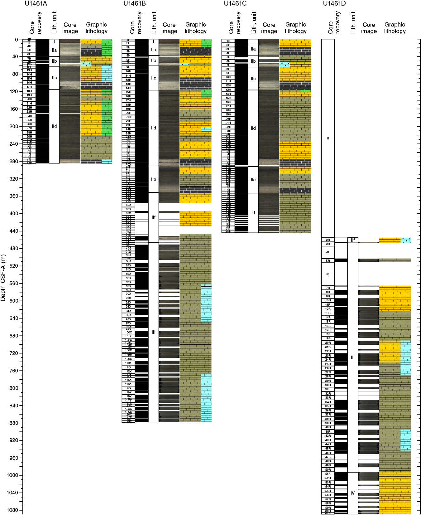
Figure F4. Lithostratigraphic summary, Holes U1461A–U1461D.
Table T4. Thin section samples, Site U1461. Download table in .csv format.
Table T5. Semiquantitative XRD analysis of dominant mineral phases, Site U1461. Download table in .csv format.
The lithologic descriptions are based on sediments recovered from Holes U1461A (0–284.71 m core depth below seafloor [CSF-A]), U1461B (0–877.74 m CSF-A), U1461C (0–443.88 m CSF-A), and U1461D (0–1088.92 m CSF-A). Thin section observations are based primarily on samples from Holes U1461A and U1461B (Table T4), supplemented by data from Holes U1461C and U1461D. Holes U1461A–U1461D were aligned based on drilling depth and correlation of lithologic boundaries (Figure F5). All XRD analyses were semiquantitative and performed on bulk sediment samples (Table T5).
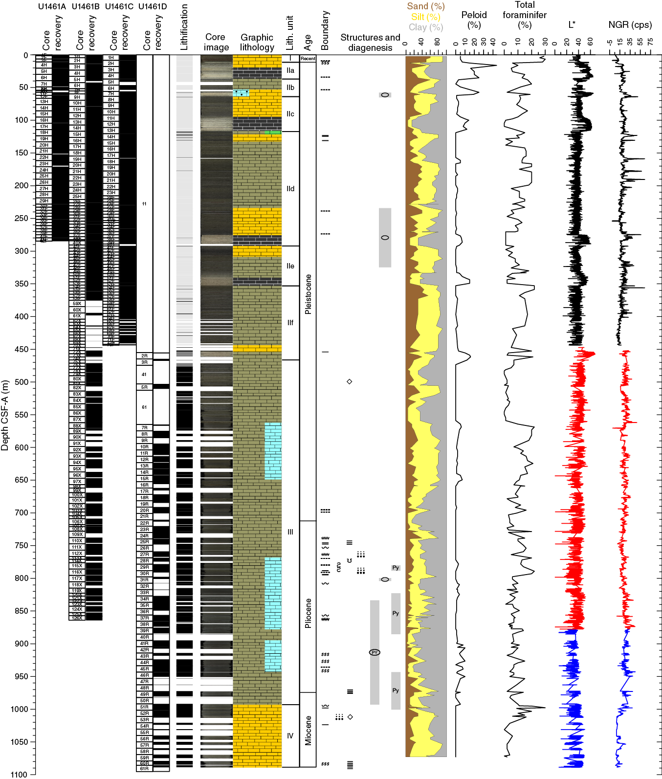
Figure F5. Smear slide summary, Holes U1461B–U1461D.
Unit I
- Intervals: 356-U1461A-1F-1, 0 cm, through 4H-1, 0 cm; 356-U1461B-1H-1, 0 cm, through 2H-5, 90 cm; 356-U1461C-1H-1, 0 cm, through 2H-3, 0 cm
- Depths: Hole U1461A = 0–11.00 m CSF-A (11.00 m thick); Hole U1461B = 0–11.30 m CSF-A (11.30 m thick); Hole U1461C = 0–11.40 m CSF-A (11.40 m thick)
- Age: recent–Late Pleistocene
- Lithology: unlithified greenish-gray to brown packstone
- Core quality: moderate to severe drilling disturbance, primarily soupiness
Unit I consists mainly of unlithified homogeneous olive-gray to greenish-gray packstone (Figures F4, F5). Glauconite grains are present in the uppermost part of the unit. Small benthic foraminifers are common, and bivalves are occasionally present throughout Unit I.
Smear slides
Smear slides show bioclastic sediment dominated by sand-sized benthic foraminifers and a diverse array of shell fragments (Figure F6A). Planktonic foraminifers, echinoderm spine fragments, broken sponge spicules, and well-preserved aragonitic pteropod shells are common accessory fossils. Nannofossils are present but uncommon in the fine fraction. Siliciclastic grains (i.e., quartz, mica, and other lithic grains) are present throughout the unit. Clay minerals are common in the fine fraction but decline toward the base of Unit I.
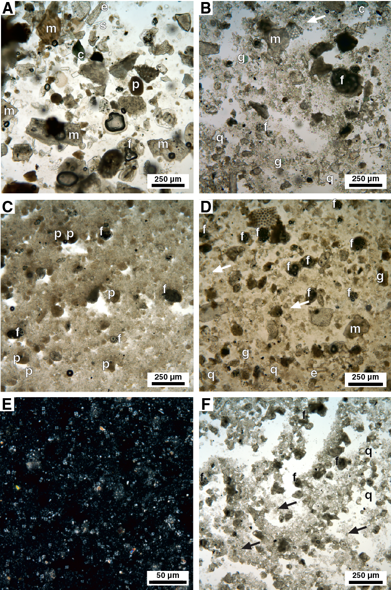
Figure F6. Representative smear slide photomicrographs of each unit.
Thin sections
No thin sections were taken in this unit.
XRD
Aragonite, with an average content of 35%, is the main carbonate mineral in five samples from Unit I (Table T5). Low-Mg and high-Mg calcite are present in nearly equal amounts with average contents of 19% and 20%, respectively. The main noncarbonate minerals are quartz (average = 27%) and minor amounts of clay minerals.
Unit II
- Intervals: 356-U1461A-4H-1, 0 cm, through 42F-CC, 21 cm; 356-U1461B-2H-5, 90 cm, through 75X-CC, 0 cm; 356-U1461C-2H-3, 0 cm, through 73F-CC, 10 cm; 356-U1461D-2R-1, 0 cm, through 3R-3, 54 cm
- Depths: Hole U1461A = 11.00–284.71 m CSF-A (273.71 m thick); Hole U1461B = 11.30–466.40 m CSF-A (455.1 m thick); Hole U1461C = 11.40–443.88 m CSF-A (432.48 m thick); Hole U1461D = 455.0–466.98 m CSF-A (11.98 m thick)
- Age: Late–Middle Pleistocene
- Lithology: alternating beds of unlithified packstone, wackestone, and mudstone
- Core quality: slight to severe drilling disturbance, primarily soupiness and/or mixing, fragmentation, and fall-in of bioclastic gravel; XRD analysis of two bulk sediment samples from suspected fall-in within Unit II have similar mineralogical compositions dominated by aragonite and high-Mg calcite; this composition correlates best with that of Subunit IIa, which may be the source of the fall-in
Unit II is divided into six subunits (IIa, IIb, IIc, IId, IIe, and IIf in order downhole). All subunits except Subunit IIa consist of two intervals that alternate between (1) an upper, darker-colored wackestone to packstone interval and (2) a lower, light-colored mudstone to wackestone interval. Throughout Unit II, the lower interval of each subunit is always thinner than the upper interval. Subunit IIa consists entirely of light-colored mudstone to wackestone.
Subunit IIa
- Intervals: 356-U1461A-4H-1, 0 cm, through 7H-1, 0 cm; 356-U1461B-2H-5, 90 cm, through 5H-4, 25 cm; 356-U1461C-2H-3, 0 cm, through 5H-1, 0 cm
- Depths: Hole U1461A = 11.00–39.50 m CSF-A (28.50 m thick); Hole U1461B = 11.30–37.65 m CSF-A (26.35 m thick); Hole U1461C = 11.40–36.90 m CSF-A (25.50 m thick)
- Age: Late–Middle Pleistocene
- Lithology: unlithified mudstone to wackestone with occasional peloids and bioturbation
- Core quality: slight to moderate drilling disturbance, primarily soupiness, fragmentation, and fall-in of bioclastic gravel
Subunit IIa consists mainly of unlithified creamy-gray mudstone to wackestone (Figure F7A). Glauconite is common throughout and tends to occur as burrow infill. Small benthic foraminifers are present throughout the subunit with occasional macrofossils, including bivalves, gastropods, scaphopods, pteropods, echinoderms, bryozoans, and solitary corals. Peloids and slight to moderate bioturbation occur intermittently throughout this subunit.

Figure F7. Unlithified cream mudstone with abundant macrofossils and peloids, Site U1461.
Smear slides
Subunit IIa is composed of fine-grained micrite, consisting mainly of small aragonite needles with minor amounts of clay minerals. Large (>500 µm) peloids are characteristic. Ooids are rare. The sediment is nearly devoid of microfossils, with small numbers of calcareous nannofossils in the fine silt to clay fraction (<4–20 µm). When present, most microfossils are benthic foraminifers, with rare planktonic foraminifers. Both benthic and planktonic foraminifers are often overgrown by calcite. Small fragments of mollusk shells, echinoderm spines, and silt-sized sponge spicules are present in minor amounts. Heavily micritized ascidian spicules occur sparsely throughout this subunit. Siliciclastic grains are rare and, when present, range from medium- to coarse-silt size. Flakes of silt-sized mica are present in minor amounts.
Thin sections
No thin sections were taken in Subunit IIa.
XRD
Aragonite, with an average content of 79%, is the main carbonate mineral in four samples from Subunit IIa (Table T5). Low-Mg and high-Mg calcite are present with average contents of 7% and 12%, respectively. Quartz is present in only two samples (average = 3%), and clay minerals are absent.
Subunit IIb
- Intervals: 356-U1461A-7H-1, 0 cm, through 12F-1, 127 cm; 356-U1461B-5H-4, 25 cm, through 9H-1, 130 cm; 356-U1461C-5H-1, 0 cm, through 8H-1, 36 cm
- Depths: Hole U1461A = 39.50–63.17 m CSF-A (23.67 m thick); Hole U1461B = 37.65–61.10 m CSF-A (23.45 m thick); Hole U1461C = 36.90–63.86 m CSF-A (26.96 m thick)
- Age: Middle Pleistocene
- Lithology: unlithified packstone to wackestone in the upper part and partially lithified wackestone with peloids in the lower part of the subunit
- Core quality: slight to moderate drilling disturbance, primarily soupiness
Subunit IIb is divided lithologically into an upper Interval IIb1 and a lower Interval IIb2.
Interval IIb1
- Depths: Hole U1461A = 39.50–57.50 m CSF (18.00 m thick); Hole U1461B = 37.65–55.10 m CSF-A (17.45 m thick); Hole U1461C = 36.90–57.61 m CSF-A (20.71 m thick)
The upper interval of Subunit IIb consists mainly of unlithified greenish-gray packstone that grades into wackestone. Unlike Subunit IIa, glauconite and macrofossils are rare in Interval IIb1, and fossils consist of bivalves, gastropods, echinoderms, and scaphopods. Small benthic foraminifers are common throughout the interval, and peloids occur briefly in a 4 cm thick discrete peloid-rich layer (e.g., interval 356-U1461A-8H-1A, 8–12 cm).
Interval IIb2
- Depths: Hole U1461A = 57.50–63.17 m CSF-A (5.67 m thick); Hole U1461B = 55.10–61.10 m CSF-A (6.00 m thick); Hole U1461C = 57.61–63.86 m CSF-A (6.25 m thick)
The lower interval of Subunit IIb consists of partially lithified bioturbated white to cream wackestone with peloids (Figure F7A). Macrofossils (including bivalves, gastropods, bryozoans, echinoderms, scaphopods, and solitary corals) are present but more abundant in Holes U1461B and U1461C than in Hole U1461A. Concretions are also common throughout Interval IIb2 in Hole U1461C. A highly bioturbated zone (59.99–61.10 m CSF-A) at the base of Interval IIb2 in Hole U1461B is associated with a partially lithified to cemented, glauconite-rich, dark green wackestone layer that contains peloids and coralline algae encrusting a partially lithified cobble-sized intraclast.
Smear slides
Interval IIb1 has increased glauconitization compared to Subunit IIa, especially within foraminiferal tests. Sand- to coarse silt–sized grains are mainly bioclastic, with varying abundances of benthic foraminifers and mollusk fragments, and frequent echinoderm spines. The sediment is generally coarser than the more clay-sized grains of Subunit IIa, and the sand- to coarse silt–sized fraction has more quartz and other siliciclastic grains. Detrital and authigenic glauconite grains are common sedimentary accessories.
Interval IIb2 is composed primarily of carbonate mud, consisting of clay- to fine silt–sized aragonite needles with minor amounts of very fine crystalline calcite and clay minerals. Small (medium silt-sized to very fine sand-sized) and larger (>500 µm) peloids are common but decline gradually toward the base. This interval is largely unfossiliferous with only minor numbers of benthic foraminifers, rare fragments of mollusk shells and echinoid spines, and occasional ascidian spicules. The sediment becomes more fossiliferous toward the base of Interval IIb2 with increasing sand-sized shell fragments, benthic foraminifers, and echinoderm spine fragments.
Thin sections
Two thin sections from the lower interval of Subunit IIb (Table T4; Figure F8A) consist of peloidal packstones with rare bioclasts (foraminifer, echinoderm, bivalve, and bryozoan fragments). Peloids are abundant, and some are phosphatized or form aggregates. Fine grained, mostly enigmatic ooids are another important component, although the cores of most ooids are peloids. Fine sand–sized quartz grains constitute 2%–5% of the sediment. Porosity is moderate and formed mostly by vugs and rare intraparticle and moldic pores.
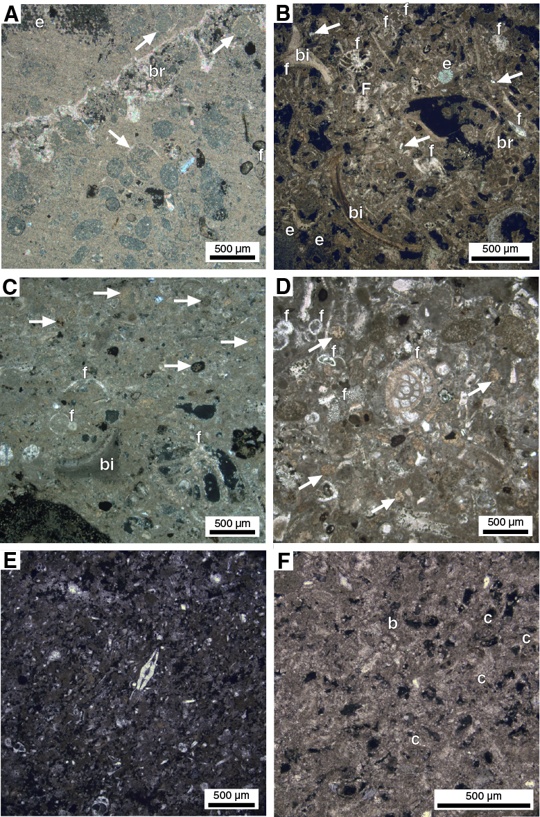
Figure F8. Packstone and wackestone.
XRD
The dominant minerals are low-Mg calcite (49%) and aragonite (36%) measured in one sample from the upper part of Subunit IIb (Table T5). The main noncarbonate minerals are quartz (15%) with minor amounts of clay minerals.
Subunit IIc
- Intervals: 356-U1461A-12F-1, 127 cm, through 18H-1, 110 cm; 356-U1461B-9H-1, 130 cm, through 15H-1, 0 cm; 356-U1461C-8H-1, 36 cm, through 13H-5, 61 cm
- Depths: Hole U1461A = 63.17–115.20 m CSF-A (52.03 m thick); Hole U1461B = 61.10–116.80 m CSF-A (55.70 m thick); Hole U1461C = 63.86–117.29 m CSF-A (53.43 m thick)
- Age: Middle Pleistocene
- Lithology: unlithified packstone to wackestone in the upper part and unlithified mudstone in the lower part of the subunit
- Core quality: generally slight drilling disturbance, primarily as soupiness and fragmentation; some core sections were destroyed by the core liner being bent during coring operations
Subunit IIc is divided lithologically into an upper Interval IIc1 and a lower Interval IIc2.
Interval IIc1
- Depths: Hole U1461A = 63.17–96.84 m CSF (33.67 m thick); Hole U1461B = 61.10–98.44 m CSF-A (37.34 m thick); Hole U1461C = 63.86–94.82 m CSF-A (30.96 m thick)
The top of the upper interval of Subunit IIc forms a transition to unlithified dark gray to dark greenish-gray packstone, which then grades into unlithified gray to olive-gray wackestone. Glauconite is present but decreases in abundance with depth. Small benthic foraminifers are common in Hole U1461A but less common in Holes U1461B and U1461C. Occasional macrofossil fragments, including bivalves, gastropods, scaphopods, and solitary corals, are present throughout the interval, and a carbonate concretion is associated with a zone of moderate bioturbation near the base (87.78 m CSF-A) of the interval in Hole U1461B.
Interval IIc2
- Depths: Hole U1461A = 96.84–115.20 m CSF-A (19.36 m thick); Hole U1461B = 98.44–116.80 m CSF-A (18.36 m thick); Hole U1461C = 94.82–117.29 m CSF-A (22.47 m thick)
The lower interval of Subunit IIc is homogeneous and composed of unlithified off-white mudstone. The transition between the cream mudstone from Interval IIc2 and olive-green packstone of Interval IId1 is characterized by increases in glauconite, bioturbation, and cementation (Figure F9). Glauconite is sparse throughout most of the interval, with occasional small concentrations. Bioclasts and bioturbation are also rare.
Figure F9. Boundary between Subunit IIc and Subunit IId.
Smear slides
Interval IIc1 contains bioclast-rich sediment with a marked increase in glauconite grains and heavily glauconitized foraminifers near the top of the interval. The main fossils are foraminifers and fragments of mollusk shells and echinoderm spines with rarer siliceous and calcareous sponge spicules. Fine crystalline euhedral dolomite occurs as an accessory in the lower part of the interval (Figure F6B).
Interval IIc2 has lithologies similar to those in Subunit IIa and Interval IIb2 that consist of peloid- and mudclast-rich sediment in a fine-grained clay-rich micrite matrix (Figure F6C). Nannofossils are rare. Microfossils, particularly benthic foraminifers and fragments of mollusks and echinoderms, increase in abundance toward the base of the interval. Most fossils are heavily overgrown by calcite. Glauconitization is rare. Siliciclastic grains are rare and occur as fine silt–sized quartz grains in most samples. Flakes of altered mica are common.
Thin sections
Three thin sections from Interval IIc1 (Table T4; Figure F8B) consist mainly of packstones with abundant bioclasts (e.g., planktonic and benthic foraminifers and fragments of echinoderms, bryozoans, and bivalves). Peloids are the most abundant nonskeletal particles, with silt-sized quartz grains, framboidal pyrite, and glauconite (<3%) scattered throughout the sections. Some peloids have dark coatings (probably manganese). The micritic matrix is at an early stage of neomorphism. Porosity is very low and rare interparticle pores are partially filled with very fine crystalline sparitic calcite.
XRD
Low-Mg calcite (63%) and aragonite (26%) are the dominant minerals in one sample from Interval IIc1, with minor amounts of quartz (10%) and clay minerals (Table T5). Aragonite (68%) and low-Mg calcite (30%) are the dominant minerals in Interval IIc2, with minor amounts of quartz (2%).
Subunit IId
- Intervals: 356-U1461A-18H-1, 110 cm, through 42F-CC, 21 cm; 356-U1461B-15H-1, 0 cm, through 41F-1, 31 cm; 356-U1461C-13H-5, 61 cm, through 41F-1, 13 cm
- Depths: Hole U1461A = 115.20–284.71 m CSF-A (169.51 m thick); Hole U1461B = 116.80–290.09 m CSF-A (173.29 m thick); Hole U1461C = 117.29–292.13 m CSF-A (174.84 m thick)
- Age: Middle–early Pleistocene
- Lithology: unlithified packstone interbedded with wackestone in the upper part and unlithified mudstone in the lower part of the subunit
- Core quality: slight to severe drilling disturbance, primarily fragmentation and biscuits
Subunit IId is divided lithologically into an upper Interval IId1 and a lower Interval IId2.
Interval IId1
- Depths: Hole U1461A = 115.20–275.21 m CSF-A (160.01 m thick); Hole U1461B = 116.80–274.90 m CSF-A (158.10 m thick); Hole U1461C = 117.29–275.27 m CSF-A (157.98 m thick)
The upper interval of Subunit IId consists of unlithified packstone interbedded with and grading into wackestone. Packstone intervals are usually slightly darker (olive-gray to dark gray and green) than wackestone intervals (light olive-gray to gray). In Hole U1461A, small benthic foraminifers are associated with the transition to wackestone. Glauconite is present in variable amounts throughout the upper part of the interval. Occasional macrofossil fragments (including bivalves, gastropods, scaphopods, bryozoans, and solitary corals) are more frequent in the upper part of the interval. Carbonate concretions are present throughout but are most abundant in the lower part. In Holes U1461B and U1461C, these concretions are associated with bioturbation.
Interval IId2
- Depths: Hole U1461A = 275.21–284.71 m CSF-A (9.50 m thick); Hole U1461B = 274.90–290.09 m CSF-A (15.19 m thick); Hole U1461C = 275.27–292.13 m CSF-A (16.86 m thick)
The top of the lower interval of Subunit IId consists of unlithified creamy-gray to off-white mudstone. Bioturbation ranges from slight to common, and glauconite is common within infilled burrows. Small benthic foraminifers are present throughout the interval in Hole U1461A, whereas macrofossils (including bivalve, gastropod, echinoderm, and scaphopod fragments) occur primarily in Hole U1461B. Carbonate concretions are common throughout the interval in Hole U1461C.
Smear slides
The upper Interval IId1 transitions gradually from a matrix dominated by clay and clay-sized micrite to a fine silt–sized calcite-micrite matrix. This transition is accompanied by increasing abundances of fossil and siliciclastic grains (especially medium to coarse sand–sized quartz). Detrital and authigenic glauconite grains are common throughout. Fossils are heavily overgrown by calcite and are often partially glauconitized. Nannofossils are common in the fine silt to clay fraction. Fine- to medium-grained euhedral dolomite crystals are common in the lower half of Interval IId1 but decrease again toward the base of the interval.
Interval IId2 is composed of peloids and clay-sized particles with rare microfossils. The sediment is relatively rich in clay minerals, whereas peloids are less numerous than in previous sections. Fossils, particularly benthic foraminifers, shell fragments, and echinoderm spine fragments, increase in abundance toward the base of the interval. Microfossils are heavily cemented and overgrown, and often indeterminate. Siliciclastic grains are rare throughout the interval, whereas nannofossils are common within the clay to fine silt fraction.
Thin sections
Eight thin sections (Table T4; Figure F8C) from Interval IId1 vary from packstones to wackestones with benthic foraminifers and peloids separated by intervals of dolomitic mudstone and wackestone. Large sand-sized bivalve and echinoderm fragments and planktonic foraminifers are also present. Small benthic foraminifers and rare quartz are present in the mudstones. Micrite is at an early stage of neomorphism and conversion to microspar. Isolated euhedral dolomite crystals occur in the micritic matrix, and nodular pyrite is present within a burrow. The noncarbonate fraction consists of scarce quartz grains. Dolomitic wackestones contain ~10%–15% foraminiferal skeletal fragments and ~1%–2% quartz. Some isolated euhedral dolomite rhombs are replacing the micritic matrix and some allochems. Intraparticle, intercrystalline, and vuggy pores create an overall moderate to high porosity. This observation is consistent with moderate to high porosities for the respective cores determined by moisture and density (MAD) measurements (see Physical properties).
Two thin sections near the base of Interval IId2 contain two different microfacies (Table T4). The first section (356-U1461A-40F-1, 56–60 cm) (Figure F8D) consists of skeletal packstone with a bimodal size distribution of peloids. Some peloids have black staining (probably manganese). Skeletal fragments are mainly small benthic and planktonic foraminifers. The second section (42F-CC, 7–11 cm) consists of mudstone with rare and unidentifiable skeletal fragments and fine quartz grains.
XRD
Low-Mg calcite (62%) is the dominant mineral in seven samples from Interval IId1. Quartz (16%) and aragonite (17%) occur in similar but lesser proportions. Ca-rich dolomite, celestite, and clay minerals are present in several samples. Dominant minerals in two samples from Interval IId2 are low-Mg calcite (54%) and aragonite (44%), with traces of quartz (1%) and celestite (1%).
Subunit IIe
- Intervals: 356-U1461B-41F-1, 31 cm, through 54F-1, 0 cm; 356-U1461C-41F-1, 13 cm, through 54F-1, 0 cm
- Depths: Hole U1461B = 290.09–351.70 m CSF-A (61.61 m thick); Hole U1461C = 292.13–353.10 m CSF-A (60.97 m thick)
- Age: early Pleistocene
- Lithology: unlithified packstone grading into wackestone in the upper part and partially lithified mudstone in the lower part of the subunit
- Core quality: slight to severe drilling disturbance, primarily as fragmentation and biscuits
Subunit IIe is divided lithologically into an upper Interval IIe1 and a lower Interval IIe2.
Interval IIe1
- Depths: Hole U1461B = 290.09–337.44 m CSF-A (47.35 m thick); Hole U1461C = 292.13–340.50 m CSF-A (48.37 m thick)
The upper interval of Subunit IIe consists of unlithified homogeneous dark greenish-gray packstone grading downward into partially lithified homogeneous light olive-gray to greenish-gray wackestone. Carbonate concretions, bioturbation, and glauconite are common in the upper part of the interval. Fragments of macrofossils (bivalves, gastropods, and echinoderms) are rare throughout the interval.
Interval IIe2
- Depths: Hole U1461B = 337.44–351.70 m CSF-A (14.26 m thick); Hole U1461C = 340.50–353.10 m CSF-A (12.6 m thick)
The lower interval of Subunit IIe is partially lithified to unlithified homogeneous mudstone. It is primarily cream to creamy-gray but grades into beige and light brown colors near the base of the interval. Small fragments of macrofossils (bivalves, gastropods, and pteropods), small benthic foraminifers, and concretions are rare.
Smear slides
Interval IIe1 is rich in coarse (~10–15 µm) micrite with minor amounts of fine to medium crystalline calcite sparite. Siliciclastics are common to rare accessories, accompanied by rare detrital glauconite. Coarse silt– to sand-sized (~60–300 µm) foraminifers and mollusk shell fragments, often heavily overgrown by calcite cement, are present throughout. Echinoid spine fragments and sponge spicules are common accessories. Nannofossils are present in minor quantities within the fine silt to clay fraction. Finer grains increase toward the base of the interval, accompanied by increasing abundances of well-preserved microfossils, particularly planktonic and benthic foraminifers, and a reduction in coarser calcite micrite and sparite. The lowermost part of this interval forms a gradual transition to the more micrite- and clay-rich Interval IIe2 and contains rare fine sand–sized peloids.
The top of Interval IIe2 is characterized by a sharp increase in fine clay–sized micrite and clay minerals, increasing abundance of peloids. Larger (200–350 µm) peloids gradually become more common with increasing depth. Microfossils and shell fragments are less abundant than in Interval IIe1. The dominant fossils are benthic foraminifers, with minor amounts of planktonic foraminifers and shell fragments. Echinoid spine fragments and ascidian spicules are common accessory constituents. Quartz and other siliciclastic grains are rare to absent.
Thin sections
One thin section from Interval IIe1 (Table T4; Figure F8E) was analyzed and consists of wackestone with skeletal components and minor very fine sand–sized quartz grains.
XRD
Low-Mg calcite (63%) is the dominant mineral in one sample from the upper Interval IIe1 (Table T5). Quartz (13%) and aragonite (14%) occur in similar but lesser proportions. Ca-rich dolomite (7%), celestite (4%), and clay minerals are also present.
Subunit IIf
- Intervals: 356-U1461B-54F-1, 0 cm, through 75X-CC, 0 cm; 356-U1461C-54F-1, 0 cm, through 73F-CC, 10 cm; 356-U1461D-2R-1, 0 cm, through 3R-3, 54 cm
- Depths: Hole U1461B = 351.70–466.40 m CSF-A (114.70 m thick); Hole U1461C = 353.10–443.88 m CSF-A (90.78 m thick); Hole U1461D = 455.00–466.98 m CSF-A (11.98 m thick)
- Age: early Pleistocene
- Lithology: unlithified to lithified packstone/wackestone grades into partially lithified to lithified packstone/wackestone with features characteristic of mass transport
- Core quality: moderate to severe drilling disturbance, primarily fragmentation, biscuits, and soupiness
Subunit IIf is divided lithologically into an upper Interval IIf1 and a lower Interval IIf2.
Interval IIf1
- Depths: Hole U1461B = 351.70–454.10 m CSF-A (102.4 m thick); Hole U1461C = 353.10–443.88 m CSF-A (90.78 m thick)
The upper interval of Subunit IIf consists of dark brown to greenish-gray packstone interbedded with light greenish-gray to olive-gray wackestone in Hole U1461B and olive-gray to dark greenish-gray wackestone in Hole U1461C. Lithification increases with depth: an unlithified upper part containing frequent carbonate concretions grades into a more lithified lower part. Gastropod fragments and small benthic foraminifers are rare, and bioturbation is minimal. In Hole U1461C, the more lithified parts have more glauconite than the rest of the interval.
In Hole U1461C, the lithified parts of Cores 64F through 72F (400.1–440.84 m CSF-A) contain many soupy intervals, up to tens of centimeters thick, with greater concentrations of glauconite and coarse sand–sized grains. This interval in Hole U1461C correlates in Hole U1461B with Cores 61X through 72X (394.4–456.85 m CSF-A): these cores had little recovery and biostratigraphic data indicate mixed ages and reworking (see Biostratigraphy and micropaleontology). Except for these soupy and lithified intervals, glauconite is rare throughout Interval IIf1.
Interval IIf2
- Depths: Hole U1461B = 454.10–466.40 m CSF-A (12.30 m thick); Hole U1461D = 455.00–466.98 m CSF-A (11.98 m thick)
The lower interval of Subunit IIf is composed of partially lithified silt- to fine sand–sized cream to light green wackestone. Slight to common bioturbation occurs in the upper part of the interval. Only the base of Interval IIf2 was recovered in Hole U1461D, and it is primarily composed of lithified cream to light greenish-gray packstone with coarse glauconite grains. Low-angle cross-stratification and normal grading are present in the cream packstone section. Bioturbation is present in the basal cream sections of both Holes U1461B and U1461D, and glauconite occurs as isolated green patches and as burrow infilling.
Smear slides
The distinction between upper and lower intervals is less clear in Subunit IIf than in previous subunits.
Interval IIf1 consists of coarse-grained micrite and sparite with heavily calcite cemented microfossils. Glauconitization is present in minor amounts throughout the interval. Coarse silt– to fine sand–sized quartz grains are common siliciclastic accessory components. Fossils are dominated by benthic foraminifers and rare planktonic foraminifers with heavy calcite overgrowths and frequent glauconitization. Mollusk fragments are also common, with less abundant fragments of echinoderm spines. Siliceous and calcitic sponge spicules and bryozoan fragments are rare. The fine silt and clay fractions contain varying but generally low numbers of calcareous nannofossils.
Sediment sizes in Interval IIf2 are bimodal, with coarse silt– to fine sand–sized microfossils (mainly benthic foraminifers) and mollusk fragments in a predominantly clay-sized carbonate micrite and clay mineral matrix with minor amounts of calcareous nannofossils. Echinoid spine fragments, large (~50–150 µm) sparitic calcite grains, quartz, and small detrital glauconite grains are common accessories.
Thin sections
Five thin sections from Interval IIf1 consist of wackestones to mudstones (Table T4; Figure F8F). Peloids in the wackestones have bimodal size distributions and form ~2%–5% of the sediment. Most recognizable skeletal fragments are small foraminifers and echinoderms (including spines). Foraminiferal chambers are partially filled with sparry calcite cement, leading to reduced interparticle porosity. Bioclastic fragments in the mudstone microfacies are probably bivalves. Very fine sand–sized quartz grains are rare. Micrite is at an early stage of neomorphism and is partially converted to microspar.
Four thin sections from Interval IIf2 (Table T4; Figure F10A) consist of wackestone to packstone with ~30%–40% peloids and ~5%–15% skeletal grains. Skeletal grains include small benthic and planktonic foraminifers, echinoderm fragments, ostracods, and pteropods. Porosity is limited, and chambers of foraminifers are mostly filled with fine crystalline sparitic calcite.

Figure F10. Packstone, grainstone, and wackestone.
XRD
Low-Mg calcite (82%) is the dominant mineral in one sample from Interval IIf1. Other minerals are quartz (9%), aragonite (5%), Ca-rich dolomite (4%), and celestite (1%). In one sample from Interval IIf2, aragonite (52%) and low-Mg calcite (45%) are the dominant minerals, with minor amounts of quartz (1%), celestite (1%), and dolomite (1%).
Unit III
- Intervals: 356-U1461B-75X-CC, 0 cm, through 129X-CC, 43 cm; 356-U1461D-3R-3, 54 cm, through 51R-2, 0 cm
- Depths: Hole U1461B = 466.40–877.74 m CSF-A (411.24 m thick); Hole U1461D = 466.98–992.88 m CSF-A (525.90 m thick)
- Age: early Pleistocene–early Pliocene
- Lithology: lithified wackestone with bioturbation, pyrite, and various sedimentary features characteristic of gravity flows
- Core quality: absent to severe drilling disturbance, primarily biscuits and fragmentation
Unit III is lithified greenish-gray to olive-gray wackestone (Figure F11). Bioturbation is common throughout the unit, and burrows are often filled with coarse sand. Glauconite varies in abundance but is generally rare. Small benthic (and occasionally planktonic) foraminifers are common. Macrofossils (mainly bivalve and gastropod fragments) are uncommon throughout Unit III.
Figure F11. Lithified wackestone with common bioturbation, small benthic foraminifers, disseminated pyrite, and pyrite nodules, Hole U1461D.
Sharp to wavy, gradational, and scoured sedimentary contacts first appear at ~694.89 m CSF-A in Hole U1461B and ~604.1 m CSF-A in Hole U1461D. A variety of sedimentary features, including parallel lamination, thin bedding, grading (normal), load casts, and slump folds, start at 745.56 m CSF-A in Hole U1461B. Other features, such as planar lamination and intraclasts, occur deeper than 604.1 m CSF-A in Hole U1461D. Disseminated pyrite and pyrite nodules become common deeper than 780.11 m CSF-A in Hole U1461B and deeper than 768.95 m CSF-A in Hole U1461D.
Smear slides
Unit III forms a gradual transition from micrite-rich sediment with frequent glauconitization toward more clay mineral–rich, finer grained sediment containing abundant nannofossils. The increase in finer grained sediment is accompanied by a decrease in sparite, which becomes rare in the lowermost part of the unit. Peloids and glauconitization within larger fossils are present throughout the unit but decrease downcore. Quartz and other siliciclastic grains are present in low abundances throughout the unit (Figure F6D).
Shell fragments and foraminifers dominate the microfossil assemblage in Unit III. Planktonic foraminifers increase toward the base of the unit. Echinoid spine fragments and siliceous sponge spicules occur only in a few intervals at very low abundances. Calcareous nannofossils are a minor component in the upper part of the unit then gradually increase in the lower half of the unit from ~858 to ~900 m CSF-A (Samples 356-U1461D-37R-2, 71 cm, through 41R-4, 91 cm). The increase in calcareous nannofossils is accompanied by a marked decrease in larger microfossils. From ~900 m CSF-A to the base of the unit (992.88 m CSF-A), calcareous nannofossils are a dominant component of the fossil assemblage (Figure F6E). Rare iron-stained sand grains occur toward the bottom of the unit (e.g., Sample 356-U1461D-49R-1, 45 cm).
Thin sections
Thin sections from Unit III alternate between wackestone and packstone (Table T4; Figure F10B–F10E). Two samples from the upper part of the unit (Samples 356-U1461B-76X-1, 88–91 cm, and 79X-1, 98–102 cm) are wackestone with small benthic foraminifers and fine-grained echinoderm fragments. Foraminiferal chambers are filled with sparry calcite cement. Two samples from the middle of the unit contain fine sand–sized grains of small benthic and rare planktonic foraminifers in moderately bioturbated packstone (Samples 356-U1461B-82X-2, 18–22 cm, and 356-U1461D-7R-2, 48–52 cm) (Figure F10B). Angular silt-sized quartz grains are rare. Minor biomoldic porosity is partially filled with fine crystalline calcite sparitic cement. Four samples from the lower part of the unit consist of wackestone with mainly planktonic foraminifers and <1% silt-sized quartz (Samples 356-U1461B-91X-1, 19–23 cm, 96X-5, 109–111 cm, 356-U1461D-23R-5, 55–59 cm, and 24R-1, 38–42 cm). One thin section from Unit III is a skeletal grainstone composed of mainly planktonic and scarce benthic foraminifers with finely disseminated pyrite and approximately 5% silt-sized quartz (Sample 356-U1461B-116X-7, 35–38 cm) (Figure F10C).
XRD
Low-Mg calcite (70%) and quartz (19%) are the dominant minerals in nine samples from Unit III. Other minerals are Ca-rich dolomite (5%), aragonite (4%), and celestite (1%). Clay minerals from the illite and kaolinite group are present in nearly every sample.
Unit IV
- Interval: 356-U1461D-51R-2, 0 cm, through 61R-CC, 29 cm
- Depth: Hole U1461D = 992.88–1088.92 m CSF-A (96.04 m thick)
- Age: early Pliocene–late Miocene
- Lithology: lithified fine sand–sized packstone with bioturbation
- Core quality: slight to moderate drilling disturbance, primarily as fragmentation
Unit IV occurs only near the bottom of Hole U1461D and consists of a transition from the lithified greenish-gray to olive-gray wackestone (with varying bioturbation, disseminated pyrite, and pyrite nodules) of Unit III to lithified light greenish-gray packstone with fine sand–sized grains and bioturbation at the base of Unit IV in Sections 356-U1461D-60R-1 through 61R-CC (1079.1–1088.92 m CSF-A). The lithologic transition marking the top of Unit IV is first observed in wackestone color variations from greenish gray to light greenish gray and by light brown bands (1–3 cm thick) with sharp basal and upper contacts. The light brown beds are mainly wackestone and are first seen in Section 51R-2 (992.88 m CSF-A). The changes in color and texture are accompanied by coarser sand–sized grains infilling larger burrows, whereas benthic foraminifers and disseminated pyrite and nodules become sparse. Numerous coarse sand–sized packstone beds appear in Section 52R-4 (1005.55 m CSF-A) (Figure F12). These beds have sharp subhorizontal basal contacts and contain both large and small benthic foraminifers. The upper beds are about 3 cm thick and become thinner (1–2 cm) and less numerous with increasing depth.

Figure F12. Unit IV mudstone and sand-sized grain beds with bioturbation, Hole U1461D.
The interval between Sections 55R-1 and 56R-1 (1031.69–1040.3 m CSF-A) consists of massive lithified cream packstone with coarse sand–sized grains and slight bioturbation. Beds of sand-sized grains, defined by sharp lower contacts, are present from Sections 56R-3 through 57R-3 (1042.71–1052.55 m CSF-A). These normally graded planar laminated beds are 3–8 cm thick. Bioturbation is slight to moderate, and benthic foraminifers are sparse. From Sections 57R-CC through 59R-1 (1053.74–1069.4 m), the lithology changes from creamy-gray packstone with coarse sand–sized grains to light greenish-gray packstone with fine sand–sized grains, accompanied by more numerous mudstone beds (2–4 cm thick) with sharp subhorizontal contacts and moderate to common bioturbation (Zoophycos isp.). The lower part of Unit IV (Sections 60R-1 through 61R-CC; 1079–1088.73 m CSF-A) is light gray packstone with fine sand–sized grains, containing a few intervals of parallel laminae and moderate bioturbation. Dissolution of foraminifers has produced abundant moldic porosity.
Smear slides
Unit IV marks a sharp change from clay mineral– and nannofossil-rich sediment to micrite-rich sediment (Figure F6F). The unit is dominated by silt-sized micrite grains, with sand-sized bioclasts that are more abundant in the upper part of the unit. Fossils are primarily shell fragments and foraminiferal tests heavily altered by calcite overgrowth. Nannofossils are a minor component in the upper part of Unit IV and disappear rapidly with depth. Siliciclastic grains and iron sulfides are prominent accessory components in the upper part. Clay minerals are nearly absent throughout the unit. The bottom of the unit alternates between more micrite-rich and bioclast-rich layers containing shell fragments, echinoid spine fragments, and planktonic foraminifers. All microfossils are heavily overgrown by calcite crystals. Glauconitization and authigenic glauconite grains occur as minor accessories throughout the unit.
Thin sections
Eight thin sections from Unit IV mainly comprise interbedded foraminiferal packstones and wackestones with occasional thin beds of fining-upward packstones above wackestone intervals. The fining-upward intervals often have subhorizontal laminations and sharp basal contacts between the packstones and wackestones (Figure F10F).
Biostratigraphy and micropaleontology
Core catcher (CC) samples were processed from Site U1461 at 20 m resolution through Holes U1461A–U1461D. In Hole U1461C, sampling was targeted at the top (mudline and Cores 356-U1461C-1H through 6H; 0–53.48 m CSF-A) and deeper than ~370 m CSF-A (Samples 57F-CC through 73F-CC; 443.88 m CSF-A).
The bottom of Holes U1461A (287.7 m CSF-A) and U1461C (443.89 m CSF-A) are of early Pleistocene age (base of Biozone NN19, <1.93 Ma). The sediments retrieved from Hole U1461B (a total of 129 cores) are of Pliocene–Pleistocene age, with the bottom (879.2 m CSF-A) estimated to be older than 4.08 Ma (planktonic foraminifers). Hole U1461D was analyzed from 456.36 m CSF-A to total depth (1088.92 m CSF-A). The abundance and preservation of calcareous nannofossils and planktonic foraminifers drastically decreased from Sample 356-U1461D-52R-CC (1008.3 m CSF-A) downhole, with possible reworking and an unconformity. The bottom of Hole U1461D was dated as middle to late Miocene (<12.38–8.79 Ma; nannofossils).
The samples from Holes U1461A–U1461D contain between 5% and 91% benthic foraminifers with Cibicides spp. and Cibicidoides spp. as the most common taxa. Six assemblages can be identified by the abundances of Amphistegina lessonii, Hyalinea balthica, and Sahulia barkeri (Assemblage 1); Elphidium spp. (Assemblage 2); Neoeponides margaritifer (Assemblage 3); Uvigerina spp. (Assemblage 4); Nodosaria spp. and Stilostomella spp. (Assemblage 5); and Globocassidulina subglobosa (Assemblage 6). In the samples, 7–63 species are present. Preservation varied from medium to poor throughout the site and was affected by fragmentation and abrasion.
Calcareous nannofossils
A total of 122 smear slides were examined for biostratigraphic marker species and common taxa. Calcareous nannofossils recovered at Site U1461 represent a complete stratigraphic succession from the early Pliocene to Late Pleistocene (Biozones NN13–NN21; Table T6), from the top to 1001.7 m CSF-A (Sample 356-U1461D-51R-CC). Calcareous nannofossils are few to abundant with moderate to good preservation in samples from the Pliocene–Pleistocene sections in Holes U1461A–U1461C but are rare to few with moderate to poor preservation in the lowermost samples of Hole U1461D (1008.3–1088.9 m CSF-A) (Table T7).
Table T6. Calcareous nannofossil and planktonic foraminifer datums, Site U1461. Download table in .csv format.
Table T7. Calcareous nannofossil abundance and range charts, Site U1461. Download table in .csv format.
Pleistocene
Samples 356-U1461A-1F-CC (1.65 m CSF-A) and 356-U1461C-2H-CC (17.65 m CSF-A) and the mudline from Hole U1461C contain abundant Emiliania huxleyi and are of Late Pleistocene age (<0.29 Ma; Biozone NN21) (Figure F13A–F13D). Core catcher samples from 8.39 to 115 m CSF-A contain abundant micrometer-scale aragonite needles and nannofossils with moderate preservation and signs of overgrowth (Figure F13E–F13G); however, this did not prevent the identification of marker species (Figure F14). The top of Pseudoemiliania lacunosa, which defines the Biozone NN19/NN20 boundary (0.44 Ma), was found at similar depths in Holes U1461A–U1461C: 39.36 (Sample 356-U1461A-6H-CC), 39.94 (Sample 356-U1461B-5H-CC), and 37.06 m CSF-A (Sample 356-U1461C-4H-CC) (Figure F15A). The species Reticulofenestra asanoi (Figure F14E) was identified in Samples 356-U1461A-33F-CC through 36F-CC (247.14–260.94 m CSF-A) and Samples 356-U1461B-30F-CC through 34F-CC (244.92–263.71 m CSF-A), constraining the ages of these samples to 0.91–1.14 Ma within Biozone NN19. The top occurrence of Gephyrocapsa spp. (>5.5 µm; Figure F14F) in Sample 356-U1461B-49F-CC (332.16 m CSF-A) indicates an age of 1.24 Ma. In addition, the top occurrence of Calcidiscus macintyrei (1.6 Ma; Figure F14L–F14M) and the base of medium-sized Gephyrocapsa spp. (>4 µm, 1.73 Ma; Figure F15B) were found in Samples 356-U1461B-92X-CC (605.94 m CSF-A) and 95X-CC (631.82 m CSF-A), respectively, and in Samples 356-U1461D-7R-CC (566.92 m CSF-A) and 7R-CC (611.55 m CSF-A), respectively, indicating the basal part of Biozone NN19. The top of Discoaster brouweri, recorded in Samples 356-U1461B-100X-CC (677.47 m CSF-A) and 356-U1461D-20R-CC (700.8 m CSF-A), represents the upper boundary of Biozone NN18 (1.93 Ma; Figure F15B).

Figure F13. Calcareous nannofossils from upper 30 m of Holes U1461A and U1461C and deepest cored interval in Hole U1461D.

Figure F14. Calcareous nannofossils, Site U1461.
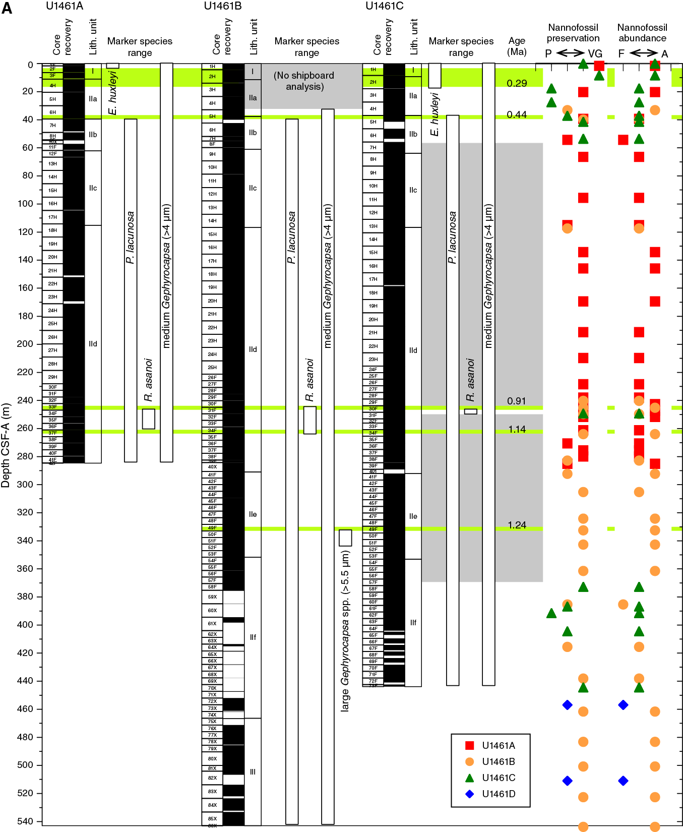
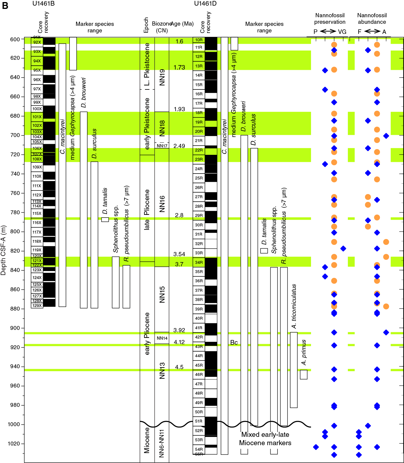
Figure F15. Depth ranges of calcareous nannofossil age markers.
The Pleistocene assemblages are characterized by different (size defined) morphotypes of Gephyrocapsa spp., P. lacunosa, and Reticulofenestra spp. (Figure F14A–F14F). Small placoliths (<3 µm) are common to very abundant in most samples and dominated by small Gephyrocapsa between 20 and 540 m CSF-A (Figures F13E–F13F, F15A). The larger Gephyrocapsa size groups are rare to common throughout the same interval (Figure F15A). Other common taxa include Calcidiscus leptoporus, Umbilicosphaera sibogae, and Helicosphaera spp.
Pliocene
Holes U1461B and U1461D recovered Pliocene strata between 728.04 m CSF-A (Sample 356-U1461B-106X-CC) and the bottom of Hole U1461B (877.74 m CSF-A) and between 713.39 and 1001.7 m CSF-A (Sample 356-U1461D-22R-CC and 51R-CC) (Figure F15B). The Pliocene/Pleistocene boundary was marked by the top of Discoaster surculus (Biozone NN16, 2.49 Ma; Figure F14Q) at 728 m CSF-A (Sample 356-U1461B-108X-CC) in Hole U1461B and 739 m CSF-A (Sample 356-U1461D-24R-7, 0–10 cm) in Hole U1461D. Discoaster tamalis (Figure F14S) is present in Samples 356-U1461B-115X-CC (785.35 m CSF-A) and 356-U1461D-33R-CC (817.63 m CSF-A), indicating an age >2.8 Ma. The top of Sphenolithus spp. (3.54 Ma; Figure F14U) in Biozone NN16 (basal part) is placed at 826.27 m CSF-A (Sample 356-U1461B-120X-CC). The Biozone NN16/NN15 boundary (3.7 Ma) is defined by the top occurrence of Reticulofenestra pseudoumbilicus (Figure F14V) in Samples 356-U1461B-122X-CC (834.71 m CSF-A) and 356-U1461D-34R-CC (836.95 m CSF-A), marking the early/late Pliocene boundary. In Hole U1461D, the top occurrence of Sphenolithus spp. is found together with the top occurrence of R. pseudoumbilicus in Sample 356-U1461D-34R-CC (836.95 m CSF-A) (Figure F15B). The top occurrence of Amaurolithus tricorniculatus (3.92 Ma; Figure F14Z) in Sample 356-U1461D-41R-CC (904.72 m CSF-A) indicates the top of Biozone NN14. The top occurrence of Amaurolithus primus (4.5 Ma; Figure F14AB) in Sample 356-U1461D-45R-CC (943.16 CSF-A) marks the upper part of Biozone NN13.
The Pliocene nannofossil assemblages are characterized by different (size defined) morphotypes of Reticulofenestra spp. and P. lacunosa. Other typical contributors to the assemblage include Discoaster spp. (Figure F14N–F14T), Calcidiscus spp., Helicosphaera spp., Pontosphaera spp., and Scyphosphaera spp. (Figure F14W–F14X). Common to abundant Sphenolithus spp. and rare Amaurolithus spp. (Figure F14Z–F14AC) are characteristic of the early Pliocene interval, where calcareous cysts of dinoflagellates (calcispheres) are also common (Figure F14AD).
Late Miocene–early Pliocene
The contact between the early Pliocene and late Miocene is difficult to place. From Sample 356-U1461D-52R-5A, 137 cm (1008.3 m CSF-A), to the bottom of Hole U1461D, the nannofossil assemblages contain common middle Miocene to early Pliocene markers, including C. macintyrei, Sphenolithus spp., and R. pseudoumbilicus (Figure F14), mixed with (fragments of) Paleogene to early Miocene taxa, including Triquetrorhabdulus carinatus (Figure F13H; range Paleogene–Biozone NN2), Triquetrorhabdulus milowii (range Biozone NN1–NN6), and Zygrhablithus bijugatus (range Paleogene–Biozone NN1; Young, 1998). A distinct decrease in overall abundance (few to rare) and degree of preservation (moderate to poor) characterizes this interval. The marker species C. macintyrei, which has its base within Biozone NN6 at 13.36 Ma, is present until the bottom sample (356-U1461D-61R-CC) at 1088.9 m CSF-A. R. pseudoumbilicus is absent in Samples 356-U1461D-52R-5, 137 cm, through 59R-CC (1008.3–1074.7 m CSF-A) but is present in Samples 60R-CC and 61R-CC, suggesting an age of 8.79 Ma for Sample 59R-CC (base absence of R. pseudoumbilicus, within Biozone NN10; Gradstein et al., 2012) and a maximum age of middle Miocene (<12.83 Ma, base of R. pseudoumbilicus within Biozone NN6; Gradstein et al., 2012) for the bottom of Hole U1461D.
The nannofossil observations are consistent with an interval of reworking of Paleogene–early Miocene sediments during the middle Miocene to earliest Pliocene, possibly representing an unconformity (Figure F15B). This may relate to a period of late Miocene tectonic deformation, similar to that in the southeast Australian basins where a regional unconformity exists around the Miocene/Pliocene boundary (Dickinson et al., 2001, 2002).
Planktonic foraminifers
Planktonic foraminifers recovered at Site U1461 constrain the stratigraphic succession from the late Miocene to recent (Table T6). The fauna at Site U1461 are more diverse than at Sites U1458–U1460, possibly due to improved cleaning methods (see Biostratigraphy and micropaleontology in the Expedition 356 methods chapter [Gallagher et al., 2017]). The fauna are also of a more tropical character, including species such as Globigerina siphonifera, Globigerinoides ruber (white), Pulleniatina obliquiloculata, and Orbulina universa (Saito et al., 1981) (Tables T8, T9, T10; Figure F16). This is also confirmed by the mudline sample from Hole U1461A (0 m CSF-A), which contained rose bengal–stained specimens of P. obliquiloculata and O. universa.
Table T8. Occurrence of main genera and species of benthic and planktonic foraminifers and additional bioclasts and minerals, Site U1461. Download table in .csv format.
Table T9. Planktonic foraminifer presence, abundance, and preservation at Site U1461. Download table in .csv format.
Table T10. Planktonic foraminifer abundance, Site U1461. Download table in .csv format.

Figure F16. Planktonic foraminifer abundance, Site U1461.
Preservation varied from poor to very good and was, in general, good in the upper 40 m of Hole U1461A (Samples 356-U1461A-1F-CC through 6F-CC). Poor preservation was observed near hardgrounds and/or intervals with abundant peloids (e.g., Sample 8H-CC [54.33 m CSF-A]; see Other bioclasts and Lithostratigraphy). Poor preservation occurred in most of the Pleistocene strata from ~50 to ~450 m CSF-A (Tables T8, T10). Moderate to good preservation was recorded for the Pliocene sections of Holes U1461B and U1461D (~675–950 m CSF-A). The abundance plot of planktonic foraminifers reflects these changes and shows that planktonic foraminifers are most abundant in the Pliocene section (Tables T9, T10; Figures F16, F17). The overall diversity varied from 2 to 18 species per sample with the highest diversity in samples deeper than 562.43 m CSF-A (Sample 356-U1461B-87X-CC), which contained up to 90% planktonic taxa relative to benthic taxa.
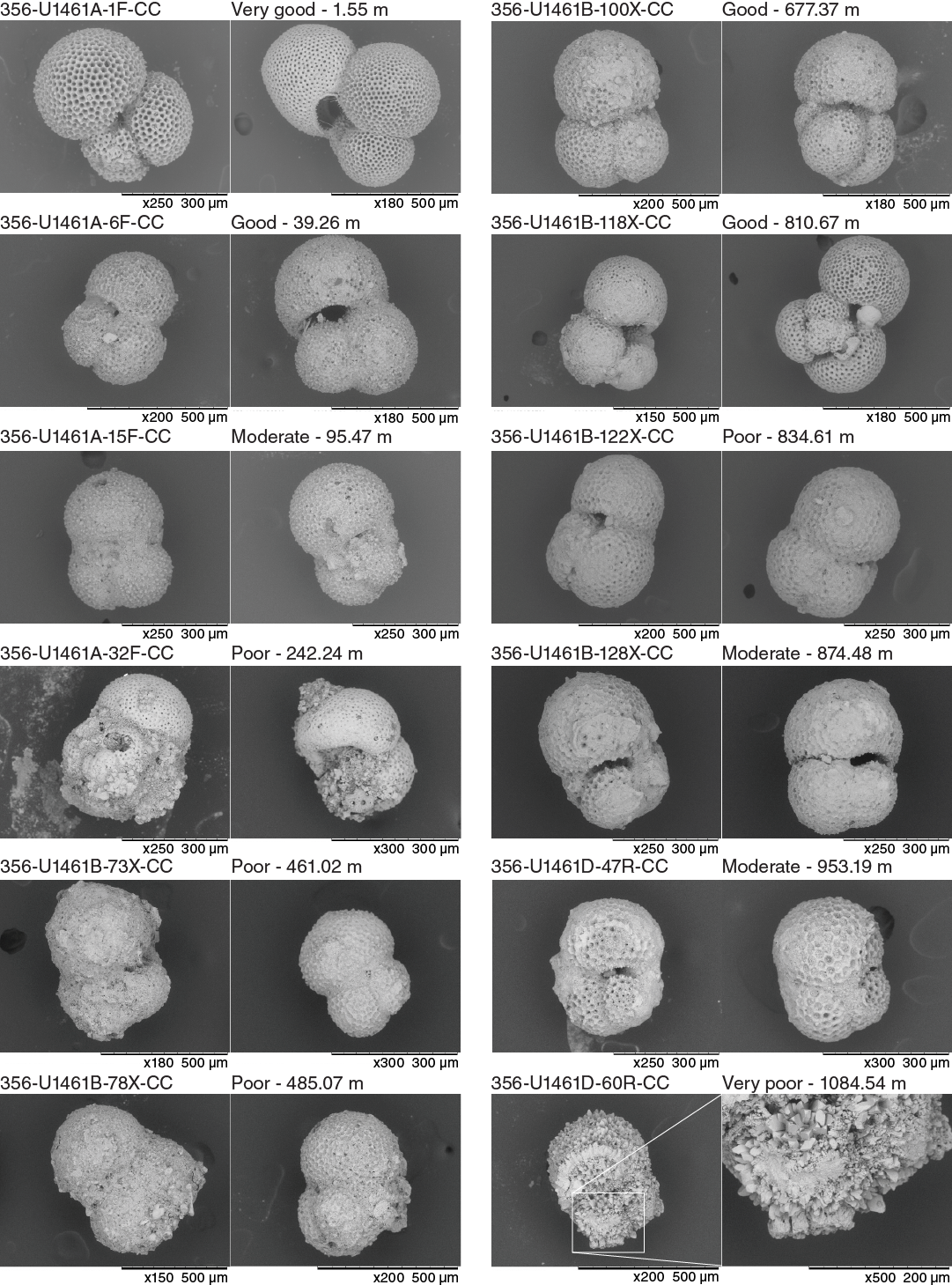
Figure F17. Typical preservation states of planktonic foraminifers, Site U1461.
The Pleistocene marker species Globorotalia tosaensis (top at 0.61 Ma) and Globorotalia truncatulinoides (base of Biozone Pt1a, 1.93 Ma) co-occur in Sample 356-U1461B-64X-CC (415.09 m CSF-A), giving an apparent base for G. truncatulinoides. The very rare occurrence of these two species in shallower intervals is probably due to their habitat depth. Extant G. truncatulinoides commonly needs water depths of 500–1000 m to complete its life cycle. The close relationship of the extinct G. tosaensis with G. truncatulinoides suggests similar conditions (Hemleben et al., 1989). So, because of the shallow modern water depths of the core sites, it is likely that the conditions were not sufficiently deep for their presence for most of the Pleistocene. In Sample 356-U1461B-100X-CC (677.47 m CSF-A), both species are present again, indicating the true base of G. truncatulinoides. These two occurrences of G. truncatulinoides are likely related to the reworked interval between ~400 and 600 m CSF-A (see Lithostratigraphy) and may actually represent the same stratigraphic level.
Early Pleistocene Biozones PL6 (top at 1.99 Ma) and PL5 (top at 2.39 Ma) are marked by the top of Globigerinoides extremus (Sample 356-U1461B-102X-CC; 694.07 m CSF-A) and top of Globorotalia limbata (Sample 356-U1461B-104X-CC; 704.94 m CSF-A) (Figure F18).
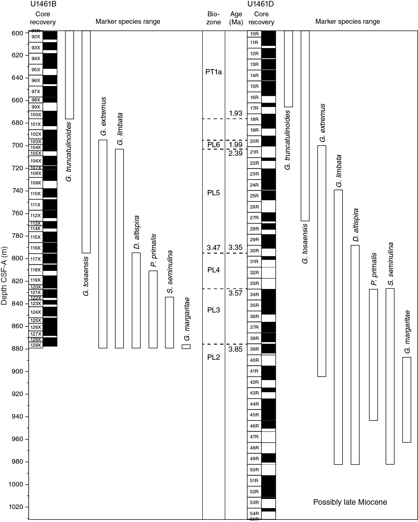
Figure F18. Range of occurrence of planktonic foraminiferal marker species for the early Pleistocene–Pliocene interval, Holes U1461B and U1461D.
The generally good preservation of the Pliocene interval, starting at ~700 m CSF-A (Samples 356-U1461B-106X-CC and 356-U1461D-22R-CC), allowed the identification of several biozone markers, including Dentoglobigerina altispira, Pulleniatina primalis, Sphaeroidinellopsis seminulina, and Globorotalia margaritae defining Biozones PL4–PL2 (3.35–4.2 Ma; Tables T8, T9; Figures F18, F19). The base of G. tosaensis (3.35 Ma) appears to overlap with the top of D. altispira (3.47 Ma) (Figure F18). This top is based on the equatorial Pacific, whereas for the South Atlantic a top of 3.13 Ma was determined (Shackleton et al., 1995; Chaisson and Pearson, 1997), suggesting a possible later top for D. altispira off the west coast of Australia. The change in coiling direction of Pulleniatina spp. from sinistral to dextral at the base of Hole U1461B in Sample 356-U1461B-129X-CC (879.2 m CSF-A) suggests an approximated early Pliocene age of 4.08 Ma (Gradstein et al., 2012) (Table T6; Figures F18, F19). Figure F18 shows a comparison for the different biozone markers in Holes U1461B and U1461D (see also Table T10). Each of these markers was present in both holes at similar depths (Figure F18). However, the change in coiling direction of P. primalis was not encountered in Hole U1461D, possibly due to an artifact of preservation. No specific age markers were found deeper than 900 m CSF-A, coinciding with decreasing quality of preservation. Identifiable planktonic foraminifers were absent beyond Sample 356-U1461D-51R-CC (1001.6 m CSF-A) with the exception of Core 356-U1461D-59R, which contained very rare planktonic foraminifers, suggesting an age no older than late Miocene (base of G. extremus, 8.93 Ma).
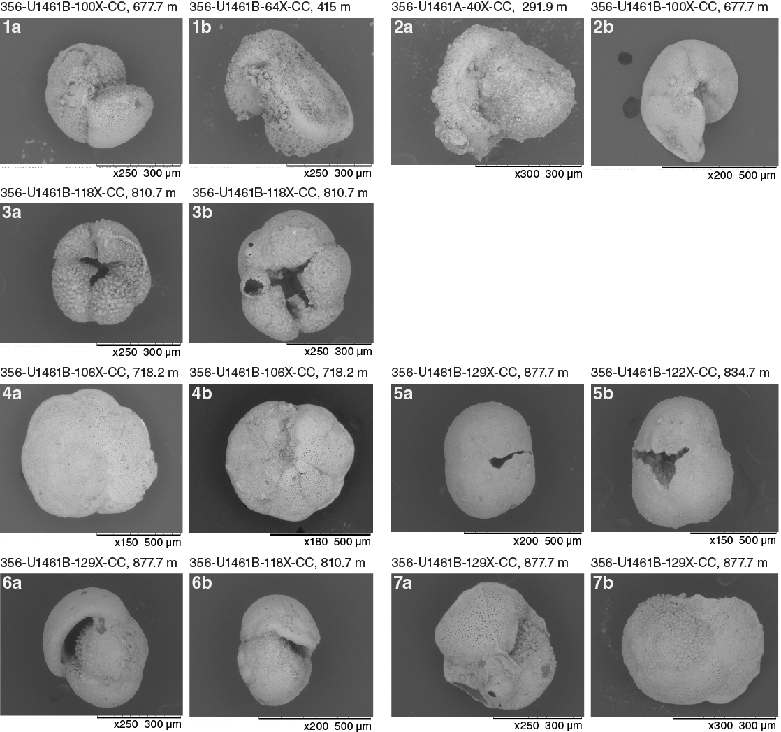
Figure F19. Planktonic foraminiferal age markers, Holes U1461A and U1461B.
Benthic foraminifers
A total of 16 core catcher samples were investigated from Hole U1461A, 36 from Hole U1461B, 8 from Hole U1461C, and 16 from Hole U1461D. Overall, the number of species present per sample ranged from 7 (Sample 356-U1461A-36F-CC; 260.92 m CSF-A) to 63 (Sample 1F-CC; 1.65 m CSF-A). The benthic foraminiferal percentage varied from 5% (Sample 356-U1461B-128-X-CC; 874.53 m CSF-A) to 91% (Sample 356-U1461C-64F-CC; 403.94 m CSF-A) (Tables T8, T11).
Table T11. Benthic foraminifer abundance, Site U1461. Download table in .csv format.
Preservation in the uppermost 114 m of Hole U1461A ranged from very good to moderate. Benthic foraminifers in the remainder of Hole U1461A (to 279.59 m CSF-A) had poor preservation. In Holes U1461B–U1461D, the majority of the samples showed poor foraminiferal preservation, although there were exceptions with moderate and even good preservation (Table T8). Preservation was affected by abrasion and fragmentation (breakage), as well as occasional cementation (coating in secondary crystals) with glauconite and pyrite. Secondary crystal coating was partially removed by ultrasonication.
Site U1461 samples largely contain the same species, but the abundance of dominant species fluctuated between several intervals. Cibicides spp. and Cibicidoides spp. are almost always present throughout, but six foraminiferal assemblages are found downcore. Except for Samples 356-U1461B-60X-CC (384.9 m CSF-A) and 356-U1461C-64X-CC (403.94 m CSF-A), all assemblages overlapped without clear boundaries, largely because these assemblages are based on the same collection of species with selected species becoming very dominant (Table T11). Samples 356-U1461B-60X-CC (384.9 m CSF-A) and 356-U1461C-64X-CC (403.94 m CSF-A) contained Assemblage 3, marked by sharp contacts, and are considered transported material. This is due to the assemblage’s dominant species not reflecting the anticipated marine setting (inner shelf/middle shelf) for that location/time and the fact that Assemblage 3 is bounded by Assemblage 2 both above and below in the core.
The first benthic foraminiferal assemblage is found in Hole U1461A, from Samples 356-U1461A-1F-CC (1.65 m CSF-A) and 4F-CC through 12F-CC (20.31–66.42 m CSF-A). This assemblage contains a range of shallow-water (0–50 m) warm to temperate species typically found on the inner shelf and photic zone. With between 46 and 63 species and very good preservation, the assemblage is dominated by epifaunal taxa and large benthic foraminifers (LBFs), including A. lessonii and smaller benthic foraminifers such as Textularia spp., Elphidium excavatum, Cymbaloporetta spp., Triloculina spp., Quinqueloculina spp., and S. barkeri (Figure F20).
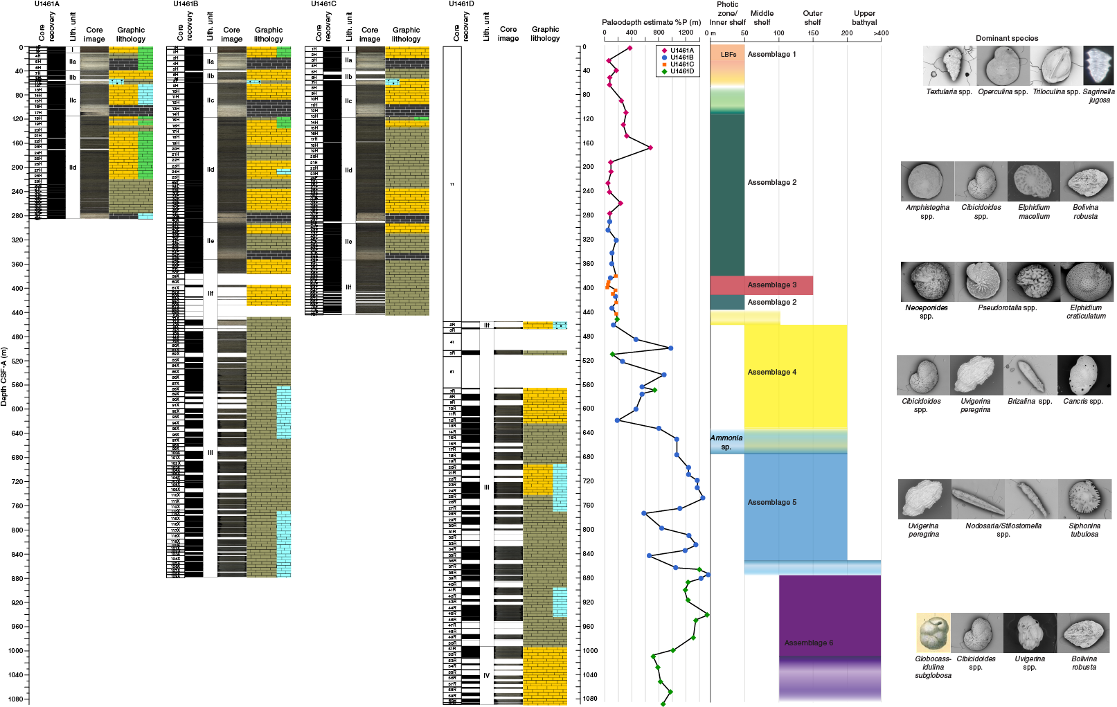
Figure F20. Dominant benthic foraminiferal species and trends, Site U1461. This figure is available in an oversized format.
The second assemblage is present in Holes U1461A–U1461C from Samples 356-U1461A-19H-CC (134.21 m CSF-A) through 356-U1461C-73F-CC (443.88 m CSF-A) (Figure F20). This assemblage has 7–34 species per sample with moderate to poor preservation and is dominated by an abundance of slightly deeper inner shelf taxa. This change in dominance occurs because there is no longer a dominance of LBF species and therefore the site location is likely below the photic zone. Species of Cibicides spp. and Cibicidoides spp. are common, and a minor fraction of this assemblage comprises shallow-water species of Amphistegina and Elphidium. In particular, A. lessonii, E. excavatum, and Elphidium macellum are found, but their tests are smaller than the test size of these species in Assemblage 1.
Assemblage 3 is only present in Samples 356-U1461B-60X-CC (384.9 m CSF-A) and 356-U1461C-64F-CC (403.94 m CSF-A) and is marked by low species diversity (only 8–10 species), abundant peloids, and better preservation (moderate) than horizons both directly above and below it. It is dominated by the large Indo-Pacific middle to outer shelf epifaunal species N. margaritifer (Gallagher et al., 2009). Other large epifaunal middle shelf species, such as Elphidium craticulatum, Pseudorotalia schroeteriana, and Lenticulina spp., are also abundant (Figure F20; Table T8). Some benthic species of this assemblage dwell in the photic zone at water depths shallower than 60 m; however, other taxa have ranges that extend to middle and outer shelf paleowater depths. This assemblage is unusual in that, unlike all other assemblages found at this site, there is no transition zone between this assemblage and others. It is present only in these two samples and bounded by Assemblage 2 in horizons both directly above and beneath it.
Assemblage 4 is present from Sample 356-U1461B-78X-CC through 97X-CC (485.17–656.64 m CSF-A) and reappears at overlapping depths in Hole U1461D (Samples 356-U1461D-2R-CC through 7R-CC; 456.36–566.92 m CSF-A) (Figure F20; Table T8). With 8–17 species per sample it has moderate to poor preservation and is dominated by epifaunal rotalids such as Cibicides spp. and Cibicidoides spp. Common secondary components of this assemblage are infaunal buliminids and uvigerinids, particularly Uvigerina peregrina and Bulimina marginata. These species typify middle to outer shelf bathymetry, slightly deeper waters than Assemblages 1 and 2, and high nutrient conditions at the sediment/water interface.
Assemblage 5 is present in Hole U1461B from Samples 356-U1461B-102X-CC through 129X-CC (694.07–877.74 m CSF-A) and in Hole U1461D (Sample 356-U1461D-37R-CC; 865.46 m CSF-A) and has between 10 and 28 species per sample. With good to poor preservation, it is identified by an increase in abundance of Siphonina tubulosa and the uniserial genera Nodosaria and Stilostomella (Figure F20; Table T8). Cibicidoides spp. and uvigerinids are also consistently abundant throughout this section. Occasional occurrences of Karreriella spp. in this assemblage indicate water depths >750 m (van Hinsbergen et al., 2005), yet dominant species in this assemblage indicate a bathymetric setting ranging from the middle shelf through to the outer shelf and upper bathyal.
Assemblage 6 is only found in the lowest part of Hole U1461D from Sample 356-U1461D-39R-CC (883.86 m CSF-A) to the deepest core catcher recovered (Sample 61R-CC; 1088.92 m CSF-A) (Figure F20; Table T8). Preservation is good to poor and there are between 8 and 20 species per sample. The most abundant species are G. subglobosa, Cibicidoides spp., Heterolepa bradyi, Cibicides wuellerstorfi, and Bolivina robusta, indicating an outer shelf to upper bathyal setting, the deepest bathymetric setting at this site.
Overall paleodepth estimates, based on the planktonic/benthic foraminifer ratio, range between 52 (Sample 356-U1461A-4F-CC; 20.31 m CSF-A) and 1588 m (Core 128X; 874.53 m CSF-A) (Table T8). Paleodepth estimates increase downcore from inner shelf to bathyal (Figure F20).
Investigated benthic foraminifer percentage and diversity are combined for all holes at Site U1461 and illustrated in Figure F21.
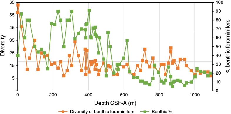
Figure F21. Benthic foraminifer diversity and benthic percentage of total foraminifers, Site U1461.
Other bioclasts
Pteropods and ostracods were present in numerous samples throughout Holes U1461A and U1461B. The mudline from Core 356-U1461A-1F (0 m CSF-A) was rich in bioclasts with ostracods, pteropods (few retained rose bengal stain), spicules, bryozoans, peloids, and bivalves. Sample 356-U1461B-73X-CC (461.12 m CSF-A) had numerous exceptionally well preserved pteropods. Ostracods indicated a change in paleoenvironment from sublittoral (Sample 356-U1461A-4H-CC; 20.31 m CSF-A) to enclosed bay (Sample 17H-CC; 114.95 m CSF-A). Peloids were found in both Holes U1461A (Sample 8H-CC; 54.3 m CSF-A) and U1461B (Sample 7H-CC; 55.0 m CSF-A). Fish teeth also occurred in some samples (e.g., Samples 356-U1461A-1F-CC [1.65 m CSF-A], 4H-CC [20.31 m CSF-A], and 356-U1461B-108X-CC [728.04 m CSF-A]).
Geochemistry
At Site U1461, 140 samples were analyzed for headspace gas content and 38 samples (5–15 cm whole rounds) for interstitial water (IW) and bulk sediment geochemistry (total organic carbon [TOC], carbonate, and total nitrogen [TN]). No IW samples were collected in Holes U1461C and U1461D, as Hole U1461C recovered a section previously sampled in Holes U1461A and U1461B and the lithology at the bottom of Hole U1461B (879.2 m CSF-A) yielded insufficient amounts of pore water. Thus, “bottom” in this geochemistry section refers to the base of Hole U1461B. Site U1461 is characterized by the highest headspace gas concentrations, highest alkalinity, and highest ammonium concentrations of all Expedition 356 sites. It is also notable that deeper than ~460 m CSF-A, the sediments smelled strongly of petroleum and hydrogen sulfide; it appears that headspace gases in this interval partially derive from thermogenic sources. Elevated salinity also characterizes the site, with a maximum value of 137 noted at 870 m CSF-A. Downhole increases in alkalinity, pH, and ammonium, along with decreasing concentrations of sulfate in the upper 100 m CSF-A, indicate the presence of a sulfate reduction zone. Site U1461 is also characterized by high calcium carbonate (mean = ~80 wt%) and generally low TOC (mean = 0.9 wt%) and TN (mean = 0.04 wt%).
Headspace gases
Headspace gas analysis for routine safety monitoring revealed the presence of methane, ethane, and propane. Methane was detected in all 140 samples with concentrations ranging from 1.6 to 39,440 parts per million by volume (ppmv) (Figure F22; Table T12). Ethane is absent in the uppermost portion of the hole but is present from 47 m CSF-A to the bottom of Hole U1461B at concentrations ranging from 0 to 45.5 ppmv. Propane was detected in 48 samples (mostly from 460 to 760 m CSF-A) at concentrations ranging from 1.6 to 85.5 ppmv. Overall, Site U1461 is characterized by elevated hydrocarbon concentrations in two intervals: 50–175 and 460–760 m CSF-A (Figure F22).

Figure F22. Hydrocarbons in headspace gases, Site U1461.
Table T12. Headspace gas contents, Site U1461. Download table in .csv format.
The ratio of methane to ethane plus propane [C1/(C2 + C3)] can be used to distinguish hydrocarbons of biogenic and thermogenic origin (O’Brien and Heggie, 1989). A ratio >1000 is considered to reflect biogenic hydrocarbons, whereas a ratio <50 is solely thermogenic; intermediate values represent a mixed origin (O’Brien and Heggie, 1989). Site U1461 can be divided into two major units based on this classification. The interval from approximately 60 to 460 m CSF-A is characterized by ratios >1000, thus suggesting biogenic methane (Figure F22). At approximately 460 to 1085 m CSF-A, lower C1/(C2 + C3) values suggest thermogenic or mixed hydrocarbon sources. In the lower unit, we often observed additional late-eluting higher molecular weight hydrocarbons (e.g., C4 or longer chain-lengths), and sediments in this interval smelled of petroleum. Therefore, it is suspected that sediments from Site U1461 deeper than 460 m CSF-A may not be suitable for some types of organic geochemical paleoenvironmental reconstructions.
Interstitial water geochemistry
Salinity is 35 at the surface and gradually increases with depth, reaching an unusually high value of 137 at 870 m CSF-A (Figure F23). The alkalinity of interstitial waters increases rapidly from the surface to a maximum value of 29.1 mM at 81 m CSF-A and subsequently decreases to values <3 mM deeper than 455 m CSF-A. The alkalinity maximum is associated with the sulfate reduction zone. pH displays a similar pattern to alkalinity.
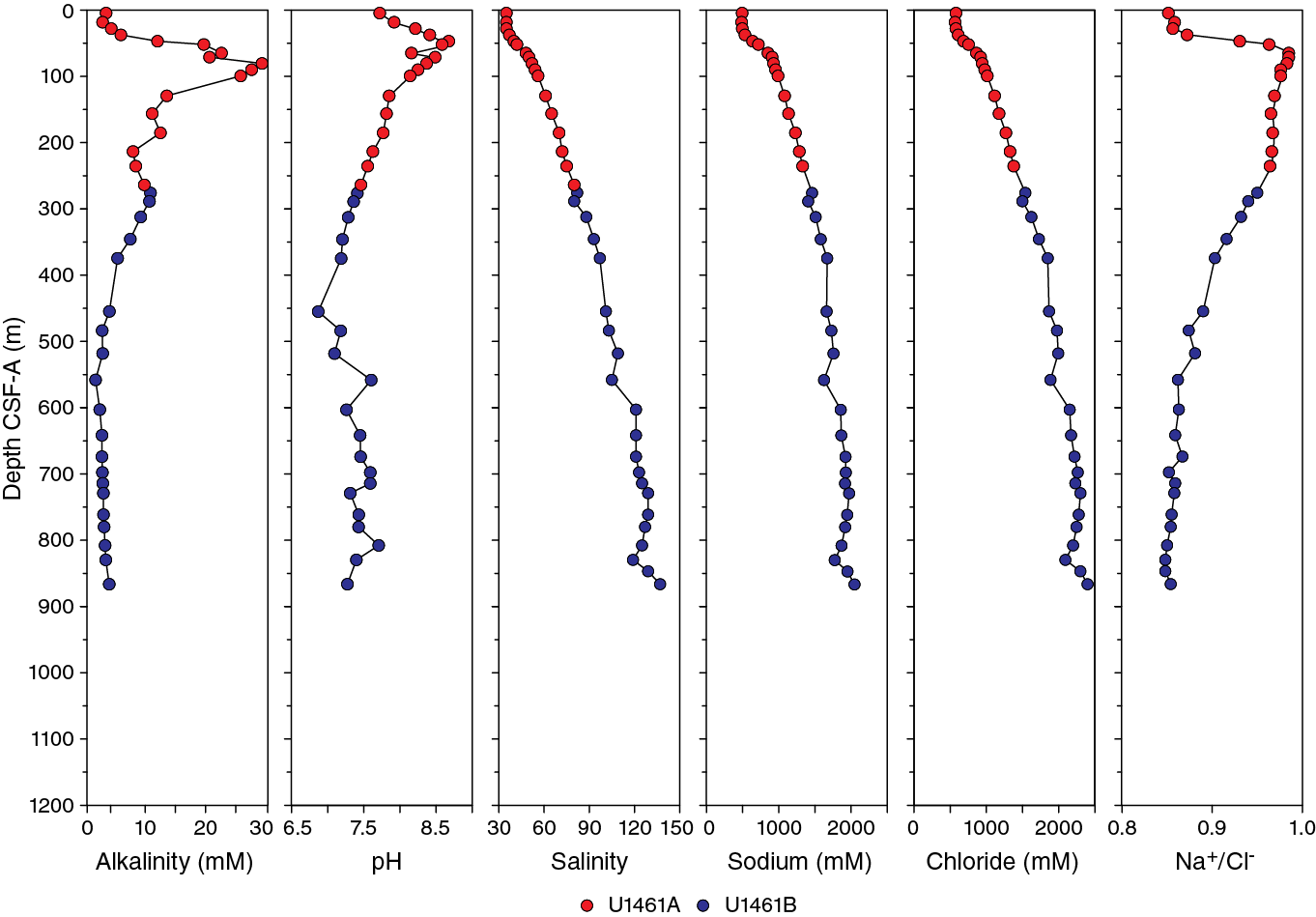
Figure F23. Alkalinity, pH, salinity, sodium, chloride, and sodium to chloride ratio, Site U1461.
Bromide, chloride, and sodium concentrations increase with increasing depth (Figures F23, F24). Calcium concentrations are generally low until 236 m CSF-A and then gradually increase toward the base of the hole (Figure F24). Sulfate concentrations display a significant decrease from 29 to 2.5 mM in the upper 52 m, then remain constant until 454.7 m CSF-A, and gradually increase to a maximum of 22 mM at the bottom of the hole. Magnesium exhibits a similar trend to sulfate with decreasing concentrations from the surface to 65 m CSF-A, then staying constant until 236 m CSF-A, and finally increasing toward the bottom of Hole U1461B. The low sulfate concentrations occur with high methane concentrations (see Headspace gases) between 52 m and 200 m CSF-A, which suggests that microbially mediated oxidation of organic matter occurs within this interval, where a hydrogen sulfide smell was also noted. Ammonium rapidly increases from 183 µM at the surface to 8270 µM at 129 m CSF-A, followed by a gradual increase to 9619 µM at 312 m CSF-A. From 312 m CSF-A to the bottom, ammonium displays a gradual decrease to 3460 µM (Figure F24). The increasing trends of alkalinity, pH, and ammonium, coincident with decreasing sulfate, indicate a sulfate reduction zone in the upper 100 m. Phosphate was present in IW samples at Site U1461 in low concentrations (<4 µM), except for between 37.5 and 99.4 m CSF-A, where elevated concentrations are noted. Potassium ranges from 6 to 10.4 mM, displaying an overall decreasing trend in the upper 100 m, followed by an increasing trend until ~300 m CSF-A, and then decreasing values until ~650 m CSF-A. Potassium concentrations increase again to the bottom of Hole U1461B, and this trend may be related to variations in clay content (see Lithostratigraphy).
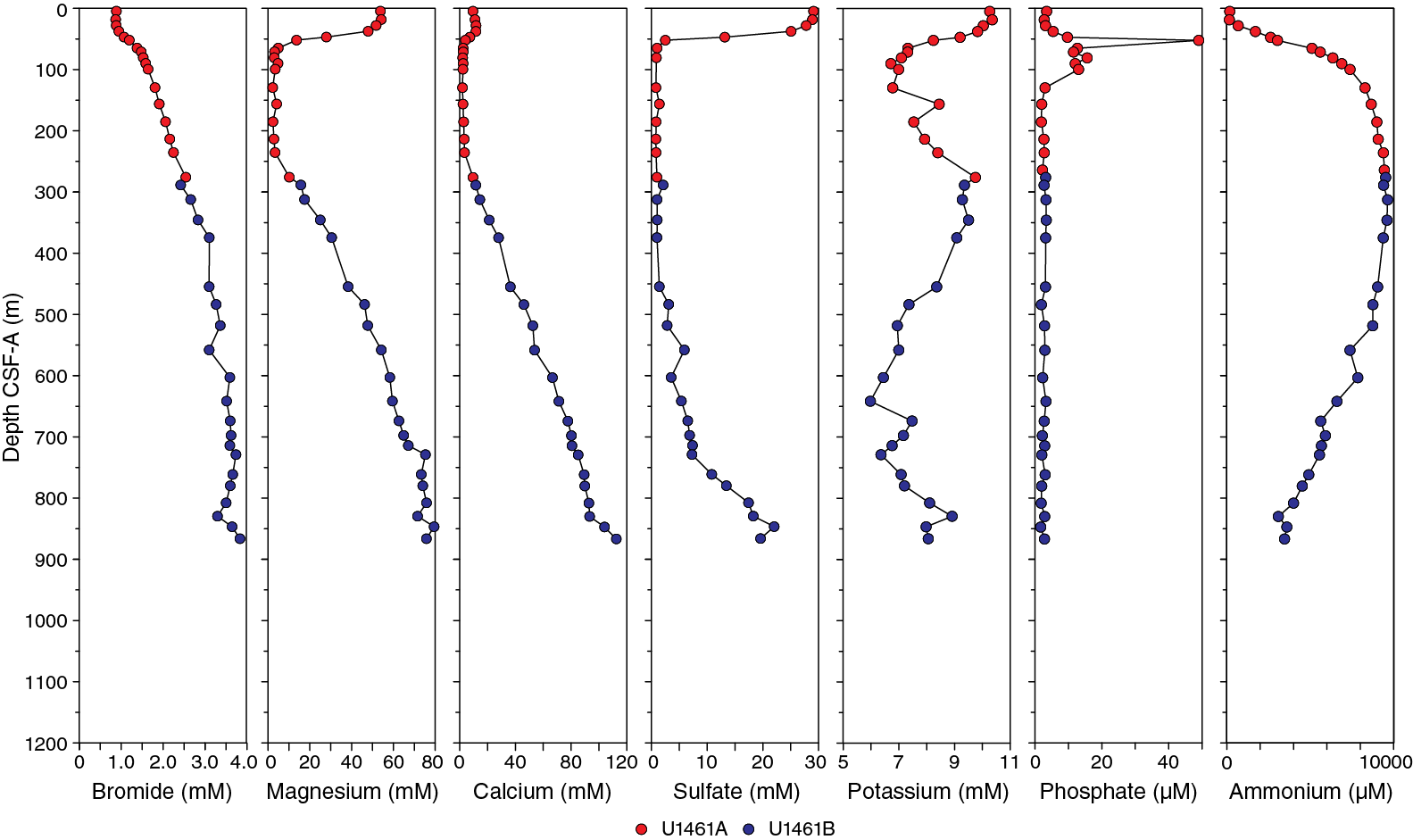
Figure F24. Major constituents of interstitial water geochemistry, Site U1461.
For the minor elements, barium concentrations are relatively low from the surface until 375 m CSF-A; from 375 to 729 m CSF-A elevated concentrations are noted followed by lower concentrations toward the bottom (Figure F25). Silicon displays a similar pattern to barium but has a smaller interval of elevated concentrations from 346 to 558 m CSF-A. Iron is present in IW samples in low concentrations (<0.5 µM), except for between 37 and 99 m CSF-A, where elevated concentrations up to 6.9 µM are noted. Strontium concentrations increase slightly from the surface to 156 m CSF-A, then rapidly increase to 518 m CSF-A where a maximum value of 2576 µM was measured, followed by decreasing values toward the bottom. Lithium remains constant in the upper 375 m CSF-A and then increases toward the bottom. Boron increases rapidly from the surface to 213 m CSF-A, where a maximum value of to 589 µM is reached, and then rapidly decreases until 558 m CSF-A. From 558 m CSF-A to the bottom, boron concentrations gradually increase.
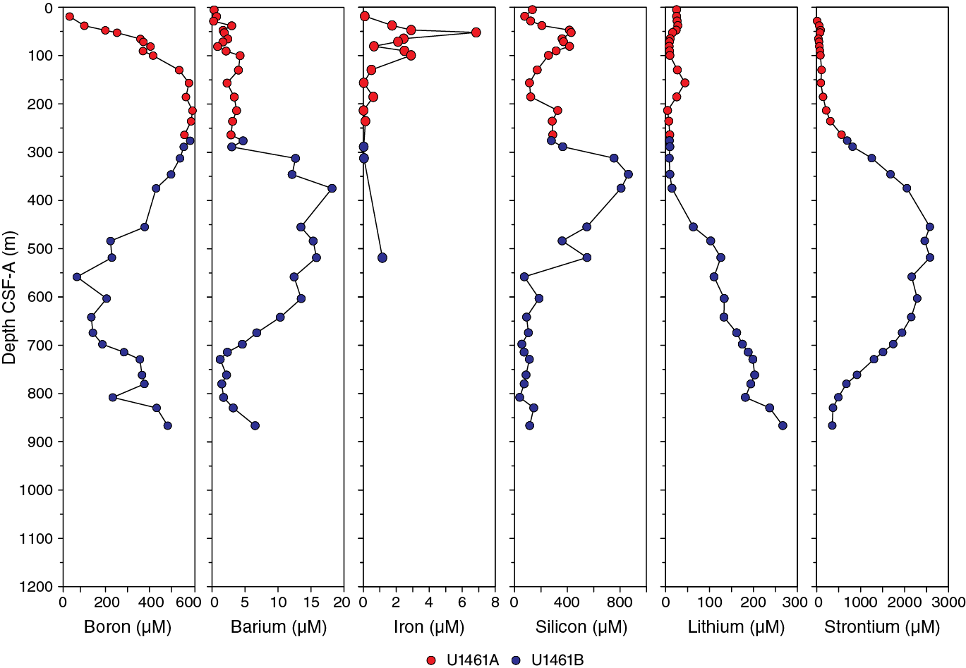
Figure F25. Minor element interstitial water geochemistry, Site U1461.
Bulk sediment geochemistry
Calcium carbonate content at Site U1461 is relatively high and ranges from 57 to 94 wt% with a mean of ~80 wt% (Figure F26). TOC is relatively low, ranging from 0.6 to 1.5 wt% with a mean of 0.9 wt%. TN is very low, ranging from 0.009 to 0.073 wt% with a mean of 0.04 wt%. A decreasing trend of calcium carbonate starts at ~400 m CSF-A, corresponding to the Unit II/III boundary (see Lithostratigraphy). The lower calcium carbonate content between 603 and 714 m CSF-A correlates with the interval of highest TOC values at the site.
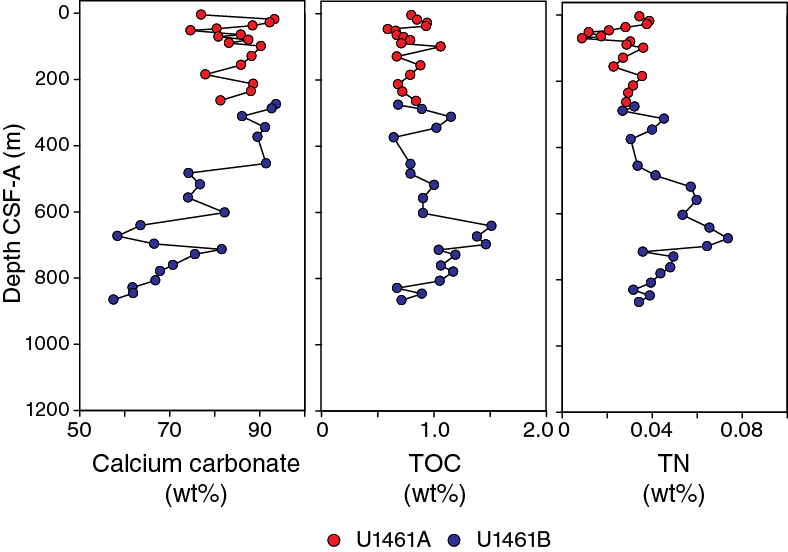
Figure F26. Bulk sediment geochemistry, Site U1461.
Paleomagnetism
Paleomagnetic investigations focused on natural remanent magnetization (NRM) and partial alternating field (AF) demagnetization measurements from Site U1461. Technical issues with the superconducting rock magnetometer (SRM), known as flux jumps, affected measurements for Holes U1461B and U1461C. A representative group of discrete samples underwent AF demagnetization and were compared to the SRM directional data sets to provide reliable magnetostratigraphic interpretations despite the technical difficulties. The problem was remedied, and measurements on the archive-half core sections for Hole U1461D were not affected by flux jumps. For Holes U1461B and U1461C, comparisons between results from the measurements on the archive-half cores and discrete samples indicate normal (negative) overprint until after the 30–50 mT demagnetization steps. Consequently, AF demagnetization up to 20–30 mT using the SRM in-line AF demagnetizer could not always yield a reliable characteristic remanent magnetization (ChRM).
Isothermal remanent magnetization (IRM) and backfield IRM acquisition curves were also carried out to investigate rock magnetism properties of Site U1461 sediments. Most of the samples reach saturation IRM (SIRM) between 100 and 300 mT, which could represent a wide range of magnetic carriers. Backfield IRM acquisition data indicate a narrow range of coercivity of remanence values between 45 and 50 mT. Some rock magnetic characteristics were confirmed by XRD results for two discrete samples from Hole U1461B.
Magnetostratigraphic interpretations for Hole U1461C place the Brunhes/Matuyama boundary (0.781 Ma) between 45 m and 65 m CSF-A and the Jaramillo Subchron (0.988 Ma) between 281 m and 316 m CSF-A. Hole U1461D magnetostratigraphic data reflect correlations with the Matuyama/Gauss (2.581 Ma) and Gauss/Gilbert (3.596 Ma) boundaries at 725 and ~827 m CSF-A, respectively, as well as the Subchron C3n.4n (Thvera) interval (4.997–5.235 Ma) close to the Pliocene/Miocene boundary. These magnetostratigraphic interpretations show agreement with the biostratigraphic datums (see Biostratigraphy and micropaleontology).
Archive-half measurements
NRM measurements on archive-half core sections from Holes U1461B–U1461D were performed with progressive stepwise AF demagnetization up to 30 mT (in 10 mT steps) at 10 cm resolution. Coring in Hole U1461A was exploratory in nature, so the magnetostratigraphic analyses concentrated on cores from subsequent holes. For Hole U1461B, APC core sections to ~370 m CSF-A were measured on the SRM. Declination values from Cores 356-U1461B-2H through 25H were corrected using data provided by the Icefield MI-5 orientation tool (see Paleomagnetism in the Expedition 356 methods chapter [Gallagher et al., 2017]). Intensity values generally ranged from 10−5 to 10−4 A/m, and inclination values were generally negative.
During measurements for Hole U1461B, we noticed flux jumps (see Paleomagnetism in the Expedition 356 methods chapter [Gallagher et al., 2017]), leading to overall instability and hence unreliable results. Section data that were affected during the NRM or 10 mT measurements were not remedied because only the 20 mT step was used for magnetostratigraphic interpretation. Flux jumps occurring during the 20 mT measurement were resolved by restarting the section measurement as another NRM step. The second NRM step was then used instead of the affected 20 mT step for data plotting and interpretation.
To distinguish reversal trends throughout the succession, we estimated an expected approximately −36.4° inclination for the latitude of Hole U1461C (20°12.8427′S) based on the geocentric axial dipole model. Hence, negative (positive) inclination values are related to normal (reversed) polarities. For Hole U1461C, we measured Cores 356-U1461C-2H through 23H, which were oriented using the Icefield MI-5 orientation tool. Corrected declination values are generally in agreement between Holes U1461B and U1461C, showing intermediate (not clustered near 0°) values at ~75 m CSF-A in Hole U1461B and ~80 m CSF-A in Hole U1461C (see Figure F27). Cores below Core 356-U1461C-23H were unoriented. Inclination and intensity data also correspond well with Hole U1461B; therefore, we did not measure sections between ~275 and ~375 m CSF-A from that hole in the interest of using this time to measure the lower interval of Hole U1461C from ~375 to ~445 m CSF-A.
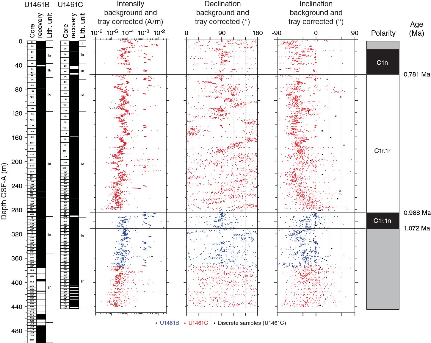
Figure F27. Magnetostratigraphic data set, Holes U1461B and U1461C.
Sediments from ~450 to 1088 m CSF-A were measured from Hole U1461D (Figure F28). Intensity values generally fall between 10−5 and 10−3 A/m with anomalous intervals of 10−2 to 10−3 A/m between ~760 and 790 m CSF-A and between ~865 and 875 m CSF-A. Normal polarity intervals are clearly defined between 638 and 655, 725 and 800, 855 and 875, and 895 and 905 m CSF-A. Two reversed polarity intervals that are recognizable span 875–885 and 915–945 m CSF-A.

Figure F28. Magnetostratigraphic data set, Hole U1461D.
Discrete sample measurements
More than 70 discrete samples from Holes U1461B–U1461D underwent AF demagnetization, 10 of which were investigated further for their magnetic properties. Eight discrete samples from Hole U1461B were analyzed using IRM and backfield IRM acquisition. IRM acquisition results, shown by the positive y-axis values in Figure F29, indicate that for most of the samples SIRM is reached between 100 and 300 mT, which can be associated with a wide range of magnetic carriers. Higher SIRM values were found for Samples 356-U1461B-6H-3, 94–96 cm (~45 m CSF-A), and 90X-2, 88–90 cm (~579 m CSF-A). Samples 8F-2, 78–80 cm, and 3H-4, 24–26 cm, reach SIRM at lower intensity values, ~7.42 × 10⁻³ and ~2.42 × 10⁻² A/m, respectively. Negative trending values on the y-axis of Figure F29 represent backfield IRM acquisition and show coercivity of remanence values where the lines cross the x-axis. All of the samples show coercivity of remanence values between 46 and 50 mT, indicating that the magnetic composition of the sediments may include mostly low-coercivity magnetic phases.
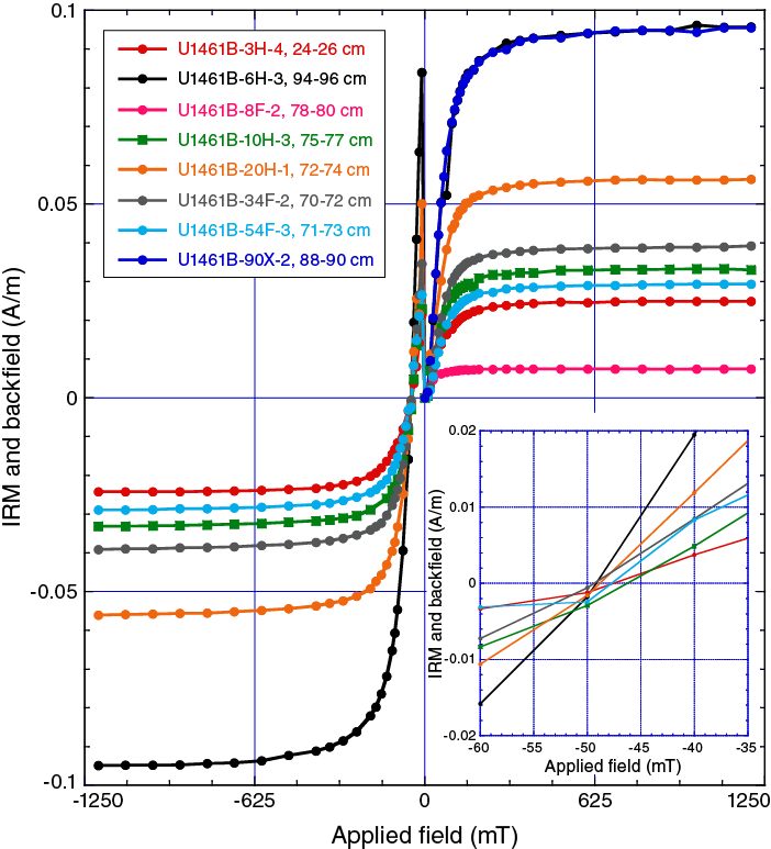
Figure F29. IRM acquisition curves for 8 discrete samples from Hole U1461B and their respective backfield IRM curves.
As a complementary procedure, XRD was performed on two samples from Hole U1461B as a way to possibly identify magnetic minerals. For at least one sample from Hole U1461B (90X-2, 88–90 cm; see Table T13), XRD indicated the presence of low (e.g., magnetite, titanomagnetite, and maghemite), intermediate (e.g., greigite), and high (e.g., hematite, greigite, and goethite) coercivity phases. The presence of high-coercivity minerals such as hematite may indicate that, if this phase is a ChRM carrier, fields reached during pass-through magnetometer measurements up to 20 mT will not reflect primary magnetization. Therefore, we rely heavily on discrete sample AF demagnetization to fields up to 80–100 mT for ChRM polarity and magnetostratigraphic interpretations.
Table T13. XRD analysis results for magnetic mineralogy content for two discrete samples, Hole U1461B. Download table in .csv format.
Discrete Sample 356-U1461B-90X-2, 88–90 cm, was also used to test the reliability of the data from archive-half sections drilled using the XCB. However, some of these samples were only demagnetized up to a peak field of 0.8 mT, an order of magnitude lower than the usual procedure. The demagnetization behavior exhibited stable directions, but the directional data showed that the ChRM component may not be attainable using pass-through SRM measurements. Therefore, SRM measurements on XCB cores were not performed during subsequent shipboard measurements.
High-resolution AF demagnetization measurements from Hole U1461C were used to help develop the magnetostratigraphy for Hole U1461C. Many samples did not show evidence of directional trends toward the origin (e.g., Sample 356-U1461C-8H2, 78–80 cm [~65 m CSF-A] in Figure F30). Despite the unstable directions, the polarity is still attributed to the ChRM after the first few demagnetization steps, and can therefore contribute to magnetostratigraphic interpretations. Samples 12H-3, 84–86 cm (~104 m CSF-A), 37F-4, 63–65 cm (~278 m CSF-A), 38F-2, 80–82 cm (~281 m CSF-A), and 46F-2, 84–86 cm (~316 m CSF-A), show more stable directional data than most samples.
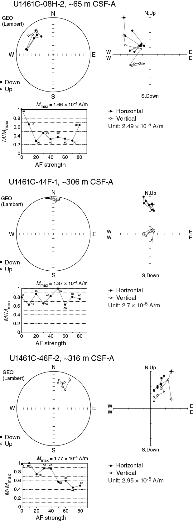
Figure F30. AF demagnetization results for 3 discrete samples, Hole U1461C.
Four discrete samples taken from Hole U1461D cores were measured and AF demagnetized to characterize the sediments. The demagnetization behavior and directional results indicate that generally, ChRM was revealed up to the 20 mT demagnetization step for Samples 356-U1461D-3R-3, 15–17 cm (464 m CSF-A), 20R-2, 110–112 cm (691 m CSF-A), and 35R-2, 49–51 cm (836 m CSF-A), but Sample 12R-4, 40–42 cm (613 m CSF-A), required higher demagnetization steps.
Magnetostratigraphy
Magnetostratigraphic interpretations from Holes U1461B and U1461C (Figure F27) are mostly based on discrete sample data. SRM results from the uppermost 350 m of Holes U1461B and U1461C show normal polarity, but discrete samples reveal reversed ChRMs starting at Section 356-U1461C-8H-2 (~65 m CSF-A) after 30 mT. This suggests that the Brunhes/Matuyama boundary (0.781 Ma) lies between Sections 6H-2 and 8H-2 (~45 and ~65 m CSF-A). In addition, discrete samples show that polarity changes again from reversed to normal between Sections 38F-2 and 46F-2 (~281 and ~316 m CSF-A), which may be indicative of the Jaramillo Subchron (C1r.1n, 0.988 Ma) (see Table T14).
Table T14. Polarity intervals and interpreted correlations, Site U1461. Download table in .csv format.
Magnetostratigraphy for Hole U1461D (Figure F27) exhibits a record of the Matuyama, Gauss, and Gilbert Chrons (Table T14), with well-defined boundaries that are in agreement with biostratigraphic results (see Biostratigraphy and micropaleontology). The Matuyama/Gauss boundary (2.581 Ma; Gradstein et al., 2012) was found by identifying Chron C2r and C2n intervals, with a transition close to the top of Core 356-U1461D-23R near the ~2.49 Ma biostratigraphic datum at 713.4 m CSF-A (top of D. surculus). The Gauss/Gilbert boundary (3.596 Ma; Gradstein et al., 2012) was identified based on the Chron C2An–C2Ar transition, which may occur at Core 34R and which matches with the ~3.59 Ma datum (top of S. seminulina) at ~817.6 m CSF-A. It is also possible that the Subchron C3n.2n (normal) interval is present from Cores 42R through 46R. At 1008.3 m CSF-A, the biostratigraphic datum that indicates late Miocene age strata approximately coincides with a reversal interval that may represent the Chron C3r reversed interval.
Physical properties
Physical properties measurements at Site U1461 were performed using the Whole-Round Multisensor Logger (WRMSL), natural gamma radiation (NGR) sensor, and discrete sampling. Light-colored sediments were discriminated by high L* values and corresponded to relatively low magnetic susceptibility (MS) and high grain density. This pattern was interpreted to result from high micrite and a low detrital clay component in these sediments. In cores that were obtained by the XCB and RCB systems, gamma ray attenuation (GRA) tended to underestimate bulk density because core liners were not fully filled due to the variation in core diameter. The same pattern was observed when MS measurements on the WRMSL and the Section Half Multisensor Logger (SHMSL) were compared. Thermal conductivity of sediments increased gradually with depth, from about 1.0 W/(m·K) in the upper portion of Holes U1461A and U1461B to ~1.8 W/(m·K) at ~1000 m CSF-A in Hole U1461D. These measurements were used in combination with downhole in situ temperature measurements to calculate a geothermal heat flux of 41.1 mW/m2. Between 125 and 450 m CSF-A, sonic velocity measurements by both WRMSL and discrete sampling were often unsuccessful because the cored material underwent a large degree of expansion, hampering such measurements. However, in the deeper parts of Holes U1461B and U1461D, discrete measurements of sonic velocity were successful and show a gradual increase with depth from ~1750 m/s (450 m CSF-A) to ~2800 m/s (925 m CSF-A). In the lower part of Hole U1461D (925–1080 m CSF-A), sonic velocities were relatively constant and ranged between 2400 and 2900 m/s. Porosity was about 60% to 70% in the top 50 m and decreased to 28%–34% at the bottom of the deepest hole (U1461D). Grain densities tended to average ~2.75 g/cm3, with high values reflecting the presence of aragonite, which occurred in varying amounts in the top half of the cored interval (upper ~600 m).
Magnetic susceptibility
MS was measured by two instruments: the WRMSL at 5.0 cm intervals and the SHMSL at 2.5 cm intervals. Sampling on the SHMSL was carried out by averaging two measurements per position in Holes U1461A and U1461C and three measurements per position in Hole U1461B and most of Hole U1461D. The values were corrected for instrument drift, as outlined in Physical properties in the Expedition 356 methods chapter (Gallagher et al., 2017) (Figures F31, F32). MS variability on a 10–20 m scale is seen in all holes and on both WRMSL and SHMSL throughout Holes U1461A and U1461C and to 375 m CSF-A in Hole U1461B (Figure F31). Large peaks were observed (Figure F32A–F32C) in Sections 356-U1461A-3F-2 (29 SI), 356-U1461B-2H-3 (27 SI), and 356-U1461C-2H-1 (22 SI) (instrument units are from the SHMSL point magnetic susceptibility [MSP]). We believe that this unusually high MS was real because it was seen in all holes with all analytical methods and corresponded to a unique unlithified homogeneous packstone (Unit I, see Lithostratigraphy). Deeper than 450 m CSF-A, MS showed a long-term trend with values increasing to the bottom of Holes U1461B and U1461D in the SHMSL data. However, this trend is less pronounced in the WRMSL data (Figure F32D). This is because the WRMSL data are processed assuming a fixed volume, corresponding to a filled APC core liner, with a diameter of 6.2 cm. In the deeper part of the site, the XCB and RCB cores had a (maximum) diameter of 5.87 cm and did not entirely fill the core liner, so MS measurements were underestimating the true susceptibility of the sediment. Therefore, we suggest that the increasing trend in the MSP data set better represented the characteristics of the deeper sediments. In addition, the WRMSL and SHMSL data showed a pronounced increase in MS deeper than 825 m CSF-A with high amplitude peaks up to 30 SI. In Hole U1461D, the high amplitude peaks ceased at ~990 m CSF-A, falling back to a background level of about 4 SI for the remainder of the hole (to ~1090 m CSF-A).

Figure F31. WRMSL MS, drift-corrected SHMSL MSP, and NGR results, Site U1461.
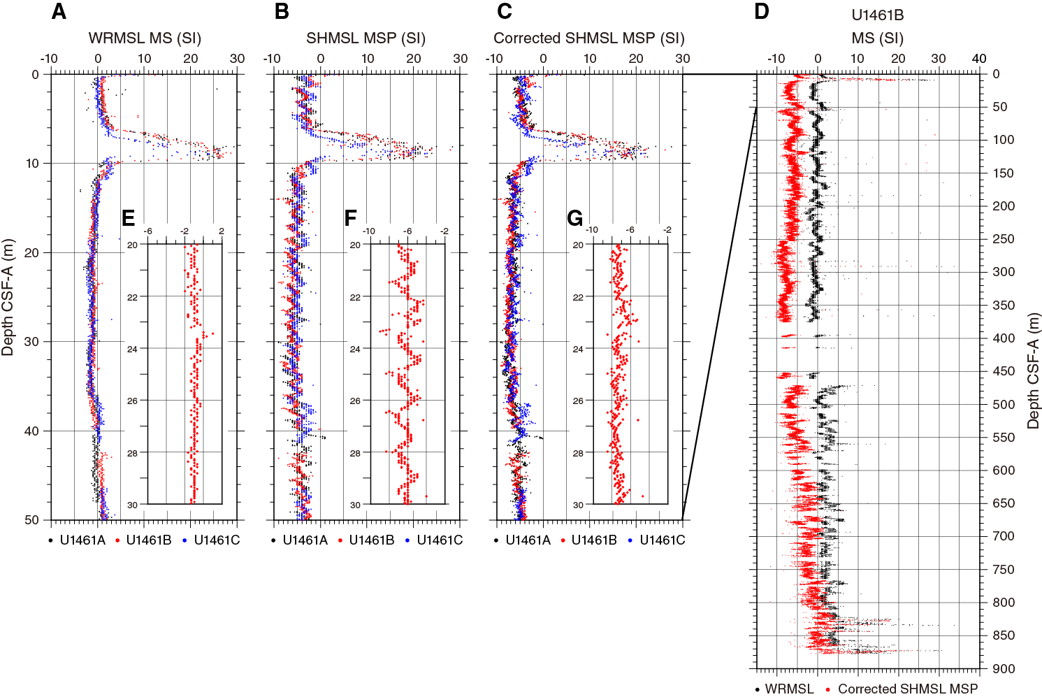
Figure F32. MS results, Site U1461.
Natural gamma radiation
NGR was measured on whole-round cores from Holes U1461A and U1461C at 20 cm intervals and at 10 cm intervals on cores from Holes U1461B and U1461D. NGR values tended to be relatively low in the top 15 m. Deeper in the section, higher peaks of up to 60 counts/s were observed, along with 10 m scale variability. Major peaks were observed at 63, 124, 160, 175, 280, 315, 562, 833, and 873 m CSF-A in Hole U1461B. These peaks were also seen in the other three holes at similar depths (Figure F31) and were used to correlate holes at this site (see Stratigraphic correlation). In the deeper section of Holes U1461B and U1461D, the NGR peaks were not as large as in the upper part. However, 10 m scale variability was still observed, allowing for correlation between these holes. In addition, Hole U1461D had relatively high values of up to 25 counts/s from 825 to 1010 m CSF-A followed by a sharp reduction to 5–10 counts/s to total depth (~1090 m CSF-A). These changes in NGR in the lower part of the section were consistent with trends in the MS record.
P-wave velocity
Two different measurements were used to determine P-wave velocities, the WRMSL (5 cm intervals) and one or two discrete measurements with the P-wave caliper on each core. Shallower than 60 m CSF-A, P-wave measurements obtained on the WRMSL were within the accepted range and consistent with discrete measurements. However, the discrete measurements demonstrate that the WRMSL P-wave velocity data include underestimated values because of the software’s misinterpretation of the first arrival of the waveform. However, the highest P-wave velocities from the WRMSL are real and range between 1500 and 1700 m/s in this depth interval. Deeper than 60 m CSF-A, P-wave velocities reported by the WRMSL are sporadic in both the depth and velocity domains. This is due to sediment expansion, so these values are unreliable and should not be used to infer sediment properties.
Although discrete samples for P-wave velocity were taken from every core, successful P-wave measurements were rare between 130 and 450 m CSF-A (Figure F33) due to the character of the sediment. In this zone, successful measurements were obtained only from lithified material. In rare instances, this lithified material consisted of rocks for which the relation to the surrounding formation was unclear. However, most reported measurements in this interval were obtained from cemented material of similar composition to the surrounding unmeasurable softer sediments. As a result, the intermittent measurements in this interval tended to be high and ranged between 2000 and 3000 m/s. Deeper than 450 m CSF-A, we consistently obtained good measurements of P-wave velocity and the values showed a gradual increase to 2700 m/s at the base of Hole U1461B and were as high as 2900 m/s at the base of Hole U1461D. In Hole U1461D, the increase in velocity stabilized at about 900 m CSF-A. Thereafter, the average velocity remained constant at about 2700 m/s to the bottom of the hole (~1090 m CSF-A).
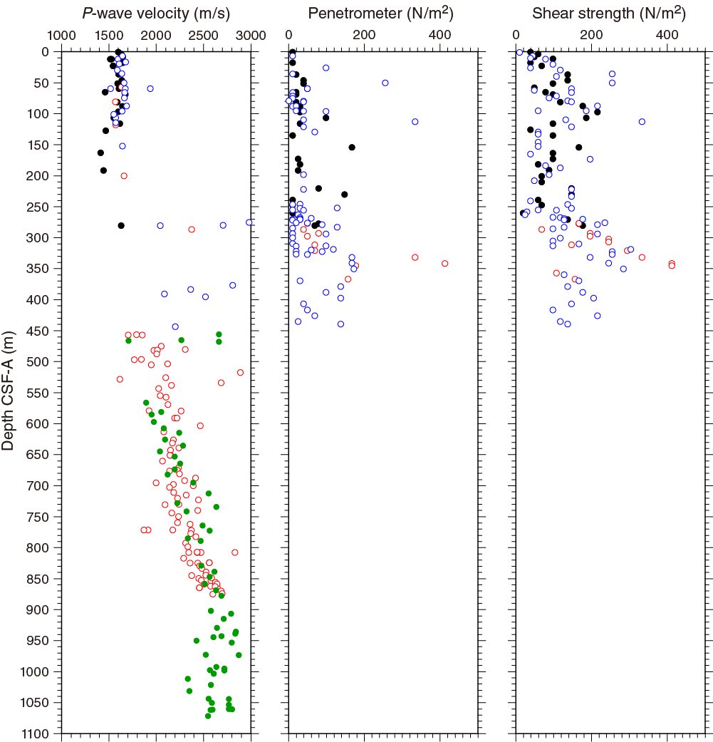
Figure F33. P-wave velocity, penetrometer, and shear strength results, Site U1461.
Gamma ray attenuation
GRA bulk density estimates were collected using the WRMSL at 5.0 cm intervals on all cores from all holes at this site (Figure F34). These results were reported with those from discrete measurements of bulk density. High bulk density peaks were present at approximately 15, 61, and 93 m CSF-A and correspond to higher NGR counts. These high bulk density peaks are confirmed by discrete samples.
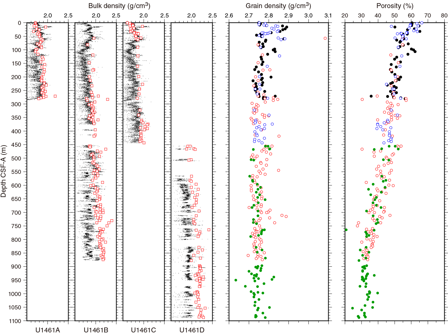
Figure F34. Bulk density, grain density, and porosity, Site U1461
Moisture and density
One or two discrete samples were collected per core in Hole U1461A. In Hole U1461B, samples were only taken every four or five cores in the interval of overlap with Hole U1461A and then one or two per core deeper than 250 m CSF-A, (Figure F34). In Hole U1461C, one sample was taken every two or three sections for the uppermost 50 m to verify results from Hole U1461A. The remainder of the overlapping section was sampled once every four or five cores. The interval deeper than 285 m CSF-A, which had piston core-refusal in Holes U1461A and U1461B, was sampled at a rate of one or two per core. These samples were generally taken from the middle of the core to avoid the effects of core disturbance. Estimates of density and porosity were calculated taking into account the high salinity values found in the pore fluids at this site (see Geochemistry). However, the impact on porosity and density was <0.2% of the results obtained assuming normal salinities.
Bulk density data analyzed through discrete samples correlated relatively well with GRA variations in the upper parts of the holes (seafloor to 450 m CSF-A) (Figure F34). Correlation coefficients between GRA and discrete sample bulk densities were R = 0.55 in Hole U1461A, R = 0.49 in the upper 450 m CSF-A of Hole U1461B, and R = 0.42 in Hole U1461C. The correlation coefficient for all data in the upper 450 m CSF-A at Site U1461 was R = 0.46. Deeper than 450 m CSF-A, the GRA values underestimated the actual bulk density because this measurement also includes a volume assumption. In the deeper sections, cores recovered with the XCB and RCB systems did not entirely fill the core liner, so bulk density measurements were underestimated. Deeper than 450 m CSF-A, discrete bulk density data show a long-term trend with values increasing to 900 m CSF-A and then becoming stable at about 2.15 ± 0.1 g/cm3 in Holes U1461B and U1461D. This is followed by a rise near the very bottom of Hole U1461D where Miocene sediments (see Biostratigraphy and micropaleontology) show a bulk density of ~2.25 g/cm3 (Figure F34).
Overall, the grain densities at the site were fairly constant at about 2.75 g/cm3. These relatively high values probably reflected the presence of aragonite, which occurred in varying amounts mainly in the upper portion of the cored interval (upper ~600 m). There were also several peaks of anomalously high grain densities from about 10 to 40 m CSF-A in Holes U1461A and U1461C. This corresponded to high concentrations of peloids and aragonite as determined via smear slides and XRD analysis (see Core descriptions and Lithostratigraphy). A grain density peak was also present at 60 m CSF-A in all three holes (U1461A–U1461C) and was also linked to an increase in peloid concentrations. An additional grain density maximum was observed at 285 m CSF-A and corresponded to a high L* and the presence of white micritic claystone with abundant aragonite. Finally, a relative high grain density horizon at 715 m CSF-A in Hole U1461B was absent in Hole U1461D at around the same depth. This high does not correspond to any change in lithology or physical properties.
Porosity values ranged between 60% and 66% in the upper 10 m, decreased to ~45%–53% at ~250 m CSF-A, and continued to decrease to ~28%–34% at the bottom of Holes U1461B and U1461D (Figure F34). Apparent low porosity measurements observed at ~13, 270, 280, 466, 589, and 731 m CSF-A were measured on anomalously cemented samples and were therefore not representative of the normal compaction trend of most sediments at this site.
A test of the sampling method for MAD was conducted at Site U1461. We discovered that the syringe sampling method for unconsolidated sediments was being conducted in two different ways. In one case, the syringe was being treated as a mini-piston core in which the inner portion of the syringe was held at the top of the sample and the outer portion was pushed down into the sample to generate a minicore with minimal disturbance. In the second method, the syringe was used as a measuring device. The inner portion was set at 10 mL (the sample size) and pressed into the half core, generating a sample with a size of approximately 10 mL. Five paired samples were taken in unconsolidated sediment at Site U1461 utilizing both of these sampling techniques at each sample location. Most of these paired samples were taken between 37 and 46 m CSF-A but one was taken at ~245 m CSF-A. The largest difference in measurements occurred when the “sample-size” method produced a 2.6% higher porosity than the piston method. This particular sample was a wet sandy sediment (Sample 356-U1461A-7H-2, 71 cm) at 41.7 m CSF-A. The other four pairs of samples produced porosities that agreed within 2% of each other or with a variation of up to 1.6%. Neither method consistently produced higher or lower porosity estimates. These measurements were made on samples taken from very wet sediments and normally compacting sediments. Based on this experiment, we conclude that the MAD sampling methods are robust and independent of the sampling approach.
Reflectance spectroscopy and colorimetry
Reflectance spectroscopy and colorimetry was performed on the archive halves of the split cores at 2.5 cm intervals. Reflectance (L*), red versus green (a*), and blue versus yellow (b*) were measured on all cores (Figure F35). At this site, the colorimetry factor that best captured variations was L*. One unique aspect of a* was an increase in greenness with depth from 450 to 875 m CSF-A.
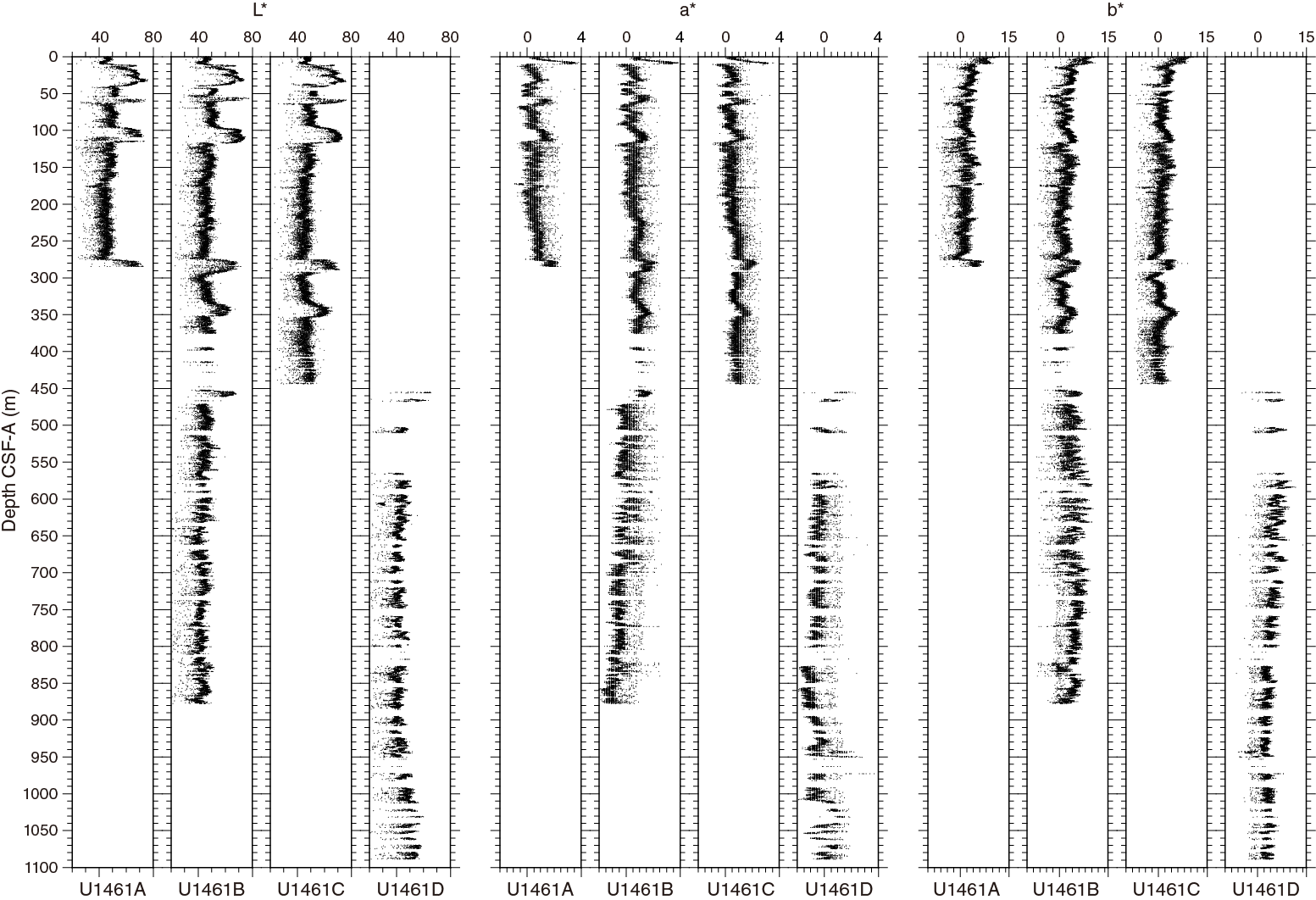
Figure F35. Reflectance spectroscopy and colorimetry, Site U1461.
Light-colored sediments (high L* values) tended to correspond to relatively low MS, possibly as a result of a higher micritic and lower detrital clay content in these sediments. Additionally, the brighter portions of the record tended to correspond with relatively high grain densities.
Discrete stress measurement
Discrete measurements of shear and normal stress were generally taken at a sampling rate of one per core. It should be noted that gas expansion in these cores resulted in a loss of strength. As a result, the values are extremely variable (Figure F33). However, there was a trend toward increasing strength with depth to the point where consolidation of the core (450 m CSF-A) made stress measurements impossible.
Thermal conductivity, temperature, and heat flux
Thermal conductivity was measured using two different devices: the needle in unconsolidated sediment and the minipuck in harder more consolidated sediment (see Physical properties in the Expedition 356 methods chapter [Gallagher et al., 2017] for details). Thermal conductivity increased from about 1.0 W/(m·K) near the seafloor to about 1.8 W/(m·K) at 1090 m CSF-A at the base of Hole U1461D (Figure F36).
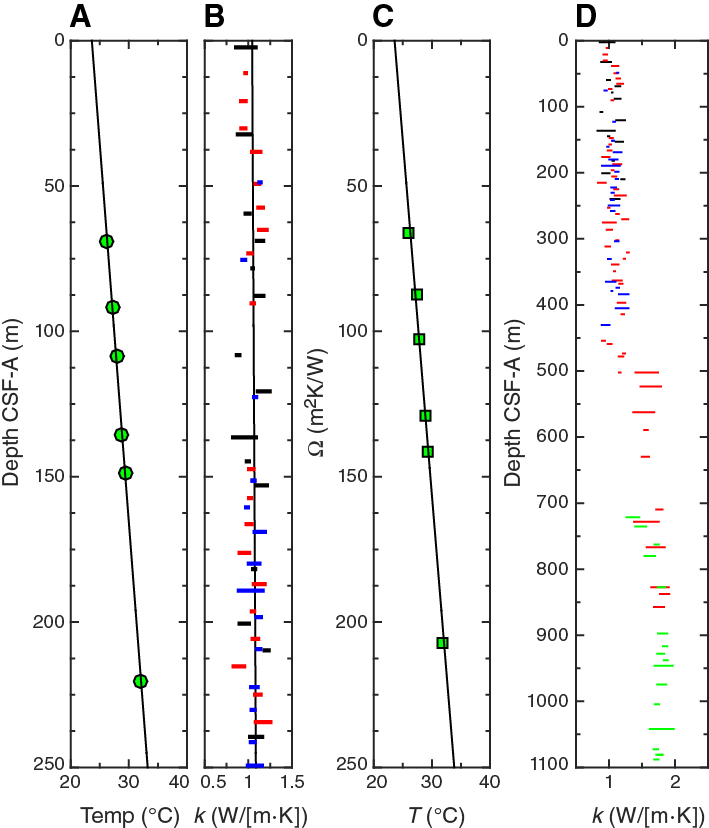
Figure F36. A. APCT-3 in situ temperature. B. Thermal conductivity. C. Thermal resistance vs. temperature. D. Thermal conductivity.
Shallower than 502.3 m CSF-A, we employed the needle probe. However, in Section 356-U1461B-81X-2, the XCB coring system resulted in lithified segments alternating with soft material that had been pulverized during coring (i.e., “biscuits and gravy” disturbance). We recognized that the needle probe had measured the conductivity of some of the artificially generated (coring-generated) soft material in this core. Therefore, we used the minipuck to estimate thermal conductivity of an undisturbed lithified piece of sediment in the split half of the same core within 2 cm of the needle probe measurement. The resulting thermal conductivity was 1.573 ± 0.069 W/(m·K), significantly higher than the result obtained by the needle probe in the disturbed wet sediment (1.161 ± 0.005 W/[m·K]). On all deeper cores, we used the minipuck on lithified pieces of sediment within the split core.
We measured the in situ temperature with the APCT-3 during piston coring in Holes U1461B and U1461C. Measurements were made in Cores 356-U1461B-9H, 13H, and 16H and Cores 356-U1461C-10H, 16H, and 24F. We were not able to estimate the temperature at the seafloor with confidence from these temperature logs. The shallowest estimate of temperature was at 69.43 m CSF-A (25.98°C). The deepest temperature reading was taken at 220.2 m CSF-A (32.01°C) (Figure F36A). Inspection and extrapolation of these temperature records suggest that they are all of good quality and together define a geothermal gradient without noticeable deviations from linearity. The resulting gradient is 38.4°C/km. From the thermal conductivities measured in cored material from all holes (Figure F36B), we were able to estimate a geothermal heat flux of 41.1 mW/m2. The Bullard plot (Figure F36C) shows a linear relationship between temperature and thermal resistance (see In situ temperature measurements in the Expedition 356 methods chapter [Gallagher et al., 2017]). Therefore, we are confident that the temperature profile has not been perturbed by fluid flow or internal heat production. We have not estimated the influence of the high sedimentation rate on the geothermal gradient, but it could be important at this site.
Downhole measurements
Downhole measurements at Site U1461 were conducted in Hole U1461D and consisted of runs with the triple combo and FMS-sonic tool strings. In contrast to the deployment of the triple combo at Site U1459, where some tools were omitted for safety reasons, the porosity, density, and resistivity tools were used at Site U1461. In addition to these three tools, borehole width, total spectral gamma ray (HSGR), and MS from the pipe depth (78.3 m wireline log matched depth below seafloor [WMSF]) to 1030 m WMSF were also measured. A single pass along the entire depth of the open hole was made with this tool string (see Operations). HSGR, bulk density, and porosity data were found to correlate with those of cores in the interval between 500 and 1000 m WMSF. In this interval, borehole diameter was close to bit size (10 inches). Higher Sin the section, the borehole is likely to have collapsed because of sediment expansion causing problems between 450 and 375 m WMSF. As a result, wireline bulk density and porosity data quality decreased in this interval, whereas the HSGR logs still correlated with core data. MS measurements were affected by temperature and were judged to be of insufficient quality for interpretation. The FMS-sonic tool failed to pass deeper than 192.7 m WMSF but yielded good-quality sonic velocity measurements. With borehole diameter exceeding 20 inches in the logged interval, the FMS resistivity images were of poor quality. Six successful APCT-3 in situ temperature measurements were made on cores from Holes U1461B and U1461C.
Depth matching
The logs were processed with depth matching on shore before the processed logs were sent back to the ship during Expedition 356. The preprocessed logs were first shifted to the seafloor (−141 m), which was determined by the step in gamma ray values observed on the triple combo main run. This differed by 2.7 m from the seafloor depth of 138.3 mbrf determined by the drillers. The depth-shifted logs were then depth matched to the HSGR log from the main pass of the triple combo. We consider that there is a 4–8 m discrepancy between the core depths (CSF-A) and wireline logging depths (WMSF). In the discussion below, we refer to all logs in WMSF and to all cores in CSF-A, realizing that the match between the two is only approximate within several meters.
Natural gamma radiation
HSGR was measured both during the down and up passes with the triple combo. Because of hole collapse in the upper section (~400 m WMSF), the data obtained from the down pass covered a larger depth interval than the up pass. In the overlapping part between the up and down log, the collected data were similar. Therefore, we present here the more extensive down pass data (Figure F37). The HSGR log showed good agreement with the NGR composite data obtained on whole-round cores from this site. In the upper 450 m WMSF, we observed relatively low HSGR, except for some distinct peaks. At 450 m WMSF there was a stepwise increase of HSGR toward values of about 35 gAPI. In the interval between 450 and 820 m WMSF, HSGR fluctuated around that level. Between 820 and 850 m WMSF, HSGR increased further to about 40 gAPI and remained at that level between 850 and 1000 m WMSF. Disregarding the uppermost 78.3 m where the HSGR signal was attenuated by the drill pipe, many NGR peaks and troughs observed from Site U1461 cores were reproduced in the downhole wireline log of Hole U1461D. Seven of the most convincing core-log correlations exhibited large variations in gamma ray values over ~5 m depth intervals. The five-window spectroscopy of the HSGR tool allowed the approximate concentrations of uranium (U) (in ppm), thorium (Th) (in ppm), and potassium (K) (in weight percent) to be determined. These HSGR data show that the large peaks in the upper 460 m (lithostratigraphic Units I and II; see Lithostratigraphy) were mainly driven by variations in U content. These U content variations tie the wireline data of Hole U1461D to the NGR measured on the cores and indicate that U-driven peaks tend to correspond to average to low K and Th concentrations. In lithostratigraphic Unit III, between 467 and 993 m CSF-A, the corresponding downhole data suggest an increase in Th and K concentrations, whereas U concentrations decrease. Most of the increase in Th and K occurred between about 740 and 830 m WMSF, whereas the decrease in U is more rapid and happens between 740 and 760 m WMSF. This is consistent with the gradual transition observed in this unit from micrite-rich sediment toward more clay mineral–rich finer grained sediment (see Lithostratigraphy). NGR measured on cores therefore shows a good correlation with the wireline Th and K concentrations in the interval between 600 and 1000 m CSF-A.

Figure F37. HSGR, NGR, and elemental U, Th, and K concentrations.
When distinct peaks and troughs in gamma ray values were correlated between the whole-round core data from Hole U1459B and wireline log data from Hole U1459C, the wireline depth was consistently shallower than the cored depth scale for any hole. The offset between wireline and coring depth varied between 4 and 8 m throughout Hole U1461D (gray horizontal lines on Figure F37).
Magnetic susceptibility
The MS data, as measured during downhole wireline logging with the triple combo, showed a gradual increase throughout the logged interval. However, the variations observed in the MS data measured on cores using the SHMSL (Figure F38) were significantly different from the variations observed in the wireline MS data. For example, the abrupt increase and decrease in MS variability at 820 and 990 m CSF-A, respectively, were not observed in the wireline MS data. However, the strong MS variability in this interval observed in the core data corresponds well with variations in K concentration obtained by wireline logging. The wireline MS measurement was affected by temperature, which increased with depth in the borehole, but this was not corrected for during processing; thus, the wireline MS data are likely overwhelmed by this factor. Therefore, the wireline MS data were judged to be of insufficient quality for interpretation.
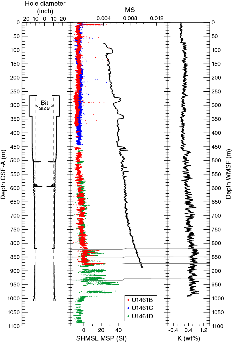
Figure F38. Magnetic susceptibility measured by triple combo, SHMSL MSP, and elemental K estimated from HSGR spectra.
Porosity, density, and resistivity
We measured porosity, density, and resistivity during the up pass with the triple combo tool string (Figure F39). Porosity, bulk density, and resistivity measurements are likely to be unreliable in the upper 450 m WMSF because of partial collapse of the hole as a result of sediment expansion (from gas; see Geochemistry). However, deeper than 450 m WMSF there was good agreement between bulk density and porosity inferred from wireline logging with those measured on discrete samples (MAD method; see Physical properties) from cores. Porosity decreased from ~48% at 450 m WMSF to ~30% at the deepest logged part of Hole U1461D (1030 m WMSF), whereas bulk density increased from 2.0 to 2.2 g/cm3 over the same interval. In addition, there was good agreement between the log- and core-based bulk densities between 230 and 310 m WMSF and between porosities obtained via wireline logging and discrete samples between 150 and 220 m WMSF. Overall, the log-based bulk density tended to either match the core-based values or show sharp excursions that underestimated the bulk density, whereas the log-based porosity values either agreed with the core-based values or overestimated them. In short, where the logging underestimated bulk density, it generally overestimated porosity compared to data obtained from discrete samples.

Figure F39. Hole U1461D diameter measured by triple combo and bulk density, porosity, and mud resistivity.
Mud resistivity fluctuated between 0.4 and 0.6 Ω from 450 to 700 m WMSF (Figure F39). Between 700 and 805 m WMSF, resistivity showed an increasing trend from 0.5 to 0.6 Ω, followed by a marked reduction to values around 0.48 Ω between 805 and 840 m WMSF. Between 870 and 1020 m WMSF, resistivity measurements fluctuated by around 0.65 Ω. Resistivity was not measured on Site U1461 cores, so core-log comparison was not possible.
Formation MicroScanner
The FMS-sonic was deployed over a limited depth interval, with the first pass carried out between 188 and 124 m WMSF and the second pass between 190 and 108 m WMSF. Hole diameter exceeded the length of the caliper (20 inches) throughout most of the logged interval (Figure F40). Throughout both runs, at least one of the four pads yielded highly conductive results, indicating that the pad was not in contact with the borehole wall. In only a small fraction of the logged interval did all four pads show simultaneous variations in resistivity. When they did, images from different pads did not show a strong correlation, suggesting that the variations were due to changes in pad contact and not variations in resistivity along the borehole wall. Moreover, the two passes did not correlate. Consequently, the FMS logs were judged to be of insufficient quality for interpretation.

Figure F40. Hole U1461D diameter and sonic velocities from Site U1461 discrete measurements and Hole U1461D wireline.
Sonic imager
Sonic velocities were measured during downhole wireline logging of Hole U1461D between 75 and 172 m WMSF. The measurements obtained during logging agreed with sonic velocities obtained from discrete measurements with the P-wave caliper from all holes of Site U1461 at depths shallower than 110 m CSF-A (Figure F40). We observed wireline sonic velocities around 1750 m/s between 78.3 and 93 m WMSF and around 1600 m/s between 93 and 110 m WMSF. However, between 110 and 172 m WMSF, wireline sonic velocities were considerably higher (1900 m/s) than the six successful discrete measurements in this depth interval (see Physical properties). We observed the maximum wireline sonic velocity (2002 m/s) at 151.8 m WMSF. There was difficulty in measuring sonic velocity on discrete samples because of sediment expansion in this depth interval, so the measurements obtained from cores were unreliable and should not be used to infer sediment properties (see Physical properties). Sonic velocities obtained by wireline logging in this interval may be more representative of the actual average sonic velocities of the sediment.
In situ temperature
Using the APCT-3, temperatures were measured in Cores 356-U1461B-9H, 13H, and 16H and Cores 356-U1461C-10H, 16H, and 24F. These temperatures were judged to be of good quality, were made between 69.43 and 220.2 m CSF-A, and were integrated with the thermal conductivities measured at the site (see Physical properties).
Stratigraphic correlation
The upper ~285 m of Site U1461 was triple cored using a combination of the piston coring (APC and HLAPC) and XCB systems. In Holes U1461A–U1461C, this interval was correlated and a splice was generated for the upper ~285 m (Figure F41; Table T15), although confidence in the correlation is not as high in some intervals between 240 and 285 m CSF-A because of low variation in NGR and MS data (e.g., Cores 356-U1461A-30F, 31F, 356-U1461B-27F through 29F, and 356-U1461C-26F through 28F) and recovery of 4.7 m cores (HLAPC) instead of full-length (9.5 m) APC cores. Although the HLAPC enabled good recovery of high-quality core overall, the relative size of the gaps between cores is greater than with the APC and a high (~114%) affine growth factor (a measure of the fractional stretching of the composite section relative to the drilled interval) also made correlation more challenging. Holes U1461B and U1461C overlap from 285 to 441 m CSF-A (base of Hole U1461C). The deeper section penetrated in Holes U1461B (Cores 81X through 126X) and U1461D (Cores 5R through 61R) was also correlated (~450–880 m CSF-A; Figure F42), but significant recovery gaps do not permit the development of a continuous spliced section.

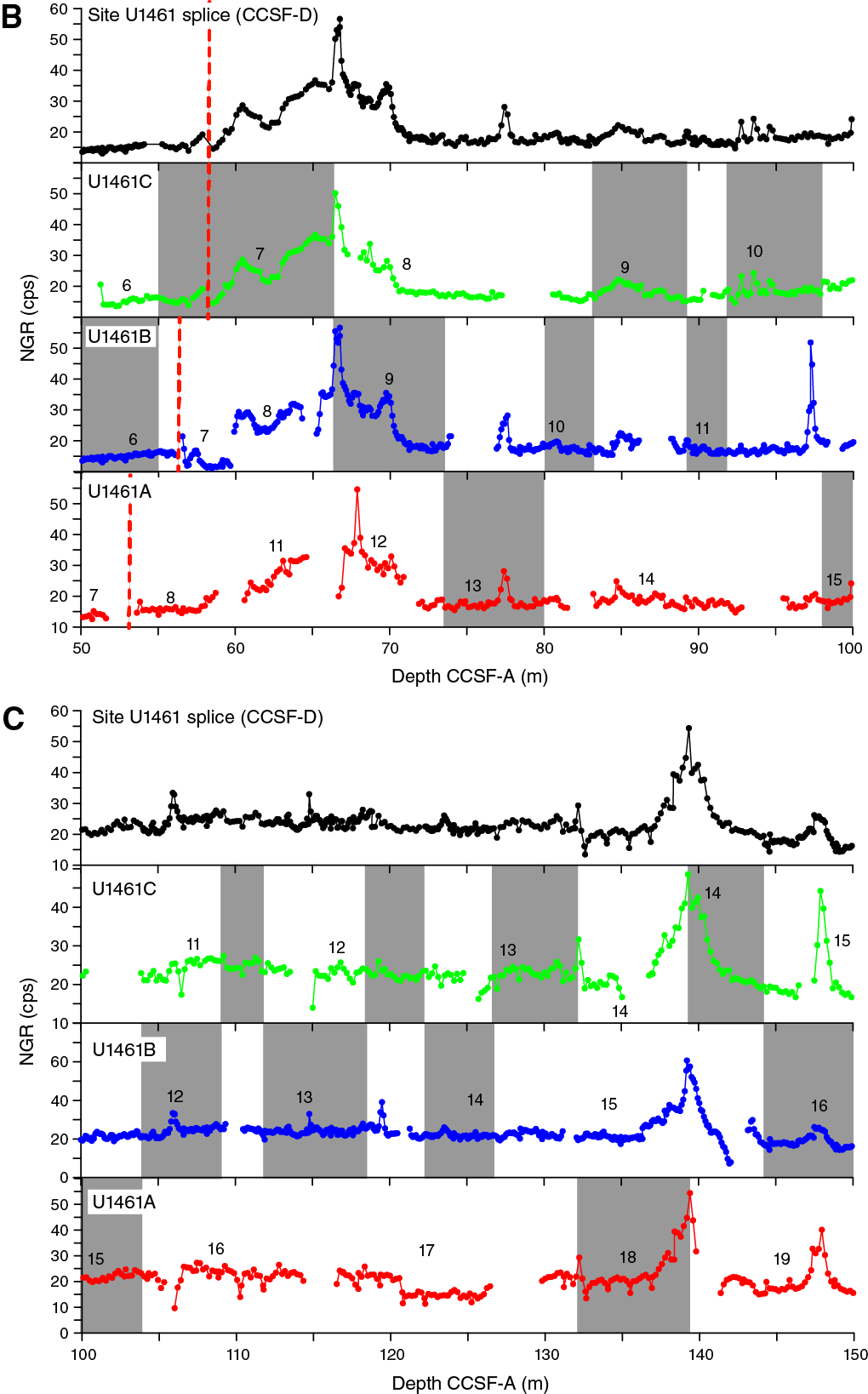

Figure F41. NGR data for the continuous splice interval in Holes U1461A–U1461C together with the final splice record.
Table T15. Splice tie point table, Holes U1461A–U1461C. Download table in .csv format.
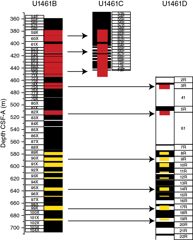
Figure F42. Drilling to recover coring gaps, Holes U1461B–U1461D.
Guidance for coring (using CSF-A)
Cores were measured for MS and GRA on the Special Task Multisensor Logger (STMSL) immediately after recovery at 10 cm intervals. The results were used to monitor for coring gaps in real time, and adjustments were made in Hole U1461C (e.g., Core 32F and the drilled interval of 289–292 m CSF-A) to avoid producing the same recovery gaps as in Holes U1461A and U1461B. NGR data were used to determine the optimal penetration depth for the mudline core of Hole U1461C.
The tidal range at Site U1461 can be as high as 2.26 m (data provided by the Australian Bureau of Meteorology, Canberra). If piston coring is started at different points in the tidal cycle, then the depth to seafloor measurements will differ between holes and the mudline shot will not hit the desired depth target, complicating correlation. Tidal heights at the approximate times of mudline shots for Holes U1461A–U1461C were monitored to avoid a drilling gap around the first core. Because tides result in a different water height, the length of the drill string must be adjusted to ensure the mudline core is shot to reach the target depth. Therefore, for APC coring in Holes U1461B and U1461C, the start depth was adjusted relative to the tidal height at the time coring began in Hole U1461A. Coring in Hole U1461D began at 455 m CSF-A using the RCB system rather than the APC system; drilling advance, as opposed to piston coring, does not require adjustments for tidal heights because tidal variations during the time spent drilling core (~45 min or less) are not large.
In addition to making adjustments to guide coring as a result of variable tidal heights, further operational guidance targeted intervals of low to no recovery. Coring deeper than ~375 m CSF-A in Hole U1461B employed the XCB system, and recovery was very low (0%–39%) between ~375–475 and 575–600 m CSF-A (see Figure F42 for core recovery) before improving in the deeper part of the hole. The first interval of low recovery in Hole U1461B (~380–450 m CSF-A; Cores 59X through 70X) was specifically targeted in Hole U1461C by the HLAPC system. Cores 356-U1461C-59F through 73F filled in some of that gap in recovery; the first interval of low recovery in Hole U1461B is graphically displayed as red boxes on Hole U1461C in Figure F42. Cores 356-U1461C-59F through 63F achieved greater than 100% recovery (~107%); recovery for Cores 356-U1461C-64F through 73F was variable (40%–104%). A second interval of low recovery in Hole U1461B occurred from ~460 to 470 m CSF-A (Cores 74X through 75X) and ~510 to 515 m CSF-A (Core 82X) and was targeted for spot coring with the RCB system in Hole U1461D (red boxes on Hole U1461D in Figure F42). A third interval of low recovery in Hole U1461B was recovered in Hole U1461D (yellow in Figure F42). It was observed that deeper than 600 m CSF-A, the core quality recovered by the RCB system (Hole U1461D) was superior to that produced by the XCB system (Hole U1461B) because severe biscuiting did not occur with the RCB system.
Correlation of the cores (to produce CCSF-A)
Coring in all four holes had variable levels of recovery, associated with hardgrounds and variable lithology. Although recovery of hardgrounds was generally good, sometimes intervals of low recovery and/or flow-in of adjacent unlithified sediments were created during piston coring. Low recovery also occurred using the XCB and RCB systems in zones with variable lithology, including hardgrounds within softer sediment. Correlation was also complicated by damage to core liners. Some core liners, particularly in Hole U1461A, were compressed during coring (e.g., Core 23H), otherwise damaged (e.g., Core 16H), or the tops of cores were contaminated by cave-in or flow-in. Cores were evaluated for drilling disturbances using the visual core descriptions (VCDs) (see Core descriptions). Peaks in the data that were recorded in the VCDs as rubble, flow-in, or crushed liners were not used for correlations.
The upper ~285 m section of Holes U1461A–U1461C was triple cored so that data from different holes could be correlated (Table T16; Figures F43, F44, F45) and a splice was generated (Table T15; Figure F41). Cores from each of the three holes were plotted in Microsoft Excel, and an offset was applied to adjust the cores to common tie points in the NGR data (Table T16; Figure F43). The level of certainty in the correlation in the upper ~240 m is graphically displayed in Figure F43 with green (high confidence) and red (low confidence) bars.
Table T16. Affine table, Holes U1461A–U1461C to 240 m CCSF-A. Download table in .csv format.
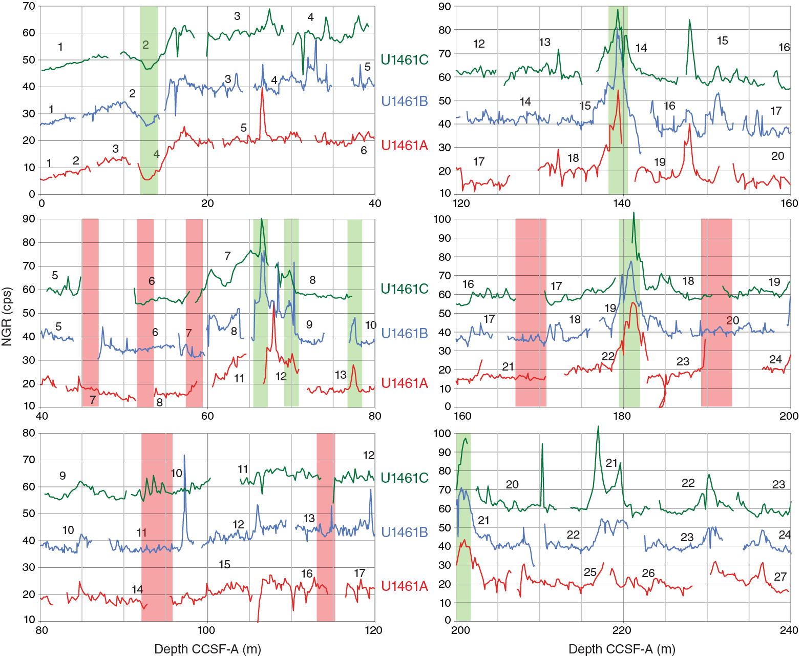
Figure F43. Correlation between Holes U1461A, U1461B, and U1461C from 0 to 240 m CCSF-A, based on NGR data.

Figure F44. Cores used to develop correlations between Holes U1461A, U1461B, and U1461C from 0 to 280 m CSF-A.
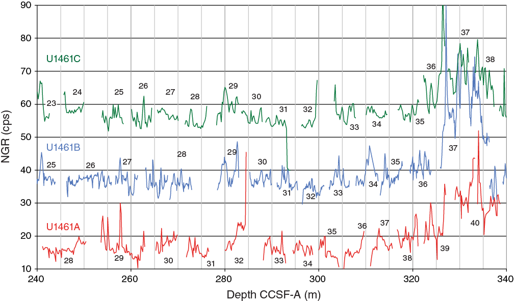
Figure F45. Correlation between Holes U1461A, U1461B, and U1461C from 240 to 340 m CCSF-A, based on NGR data.
The correlation in the upper ~240 m is anchored on the mudline established in Hole U1461C and results in a composite core depth below seafloor (CCSF-A) scale. The CCSF-A depth scale provides a common point of reference for all three holes and is typically greater than the CSF-A scale. The total depth of the CCSF-A scale is ~14% greater than the CSF-A scale (Hole U1461A grows from 279.9 m CSF-A to 319.5 m CCSF-A, Hole U1461B grows from 295.3 m CSF-A to 336.3 m CCSF-A, and Hole U1461C grows from 296.7 m CSF-A to 336.3 m CCSF-A) (Table T16). Although offsets were determined for each core, the correlation was determined for those cores with the most similar features, starting with Core 356-U1461C-1H, the mudline anchor (Figure F44). These relationships are used to develop the splice (see description below).
From ~240 to 297 m CSF-A (Cores 356-U1461A-31F through 41F, 356-U1461B-28F through 38F, and 356-U1461C-27F through 38F), below the interval for which a splice was produced (i.e., the upper ~240 m CSF-A), the level of overlap between the holes is variable, and thus, so is the certainty in the correlation, despite triple coring in the upper part of this interval (Table T16; Figure F44). Figure F45 presents the correlation between the holes; only the peaks in Cores 356-U1461A-40F, 356-U1461B-37F, and 356-U1461C-36F and 37F (~325–335 m CCSF-A) can be confidently correlated.
In the interval between 240 and 297 m CSF-A, correlation was impeded by three factors:
- The differential offsets between cores are relatively large (Table T16), so there is relatively little overlap between the 4.7 m HLAPC cores during correlation.
- Physical properties showed only low-amplitude variations (Figure F46) in distinct intervals, between ~255 and ~270 m CSF-A (Cores 356-U1461A-36F through 38F, 356-U1461B-34F through 35F, and 356-U1461C-34F through 35F), which did not allow for recognition of characteristic tie points between cores.
- Distinct differences in the NGR profile between holes is attributed in part to differences in resolution of the measurements (every 20 cm for Hole U1461A and the upper part of Hole U1461C [Cores 356-U1461C-1H through 39F] and every 10 cm for Holes U1461B and U1461D and the lower part of Hole U1461C [Cores 356-U1461C-41F through 72F]). Some of the difference between the NGR records, though, is attributed to lithologic variation, as well as differences in drilling method (HLAPC, APC, XCB, and RCB systems employed) between holes.
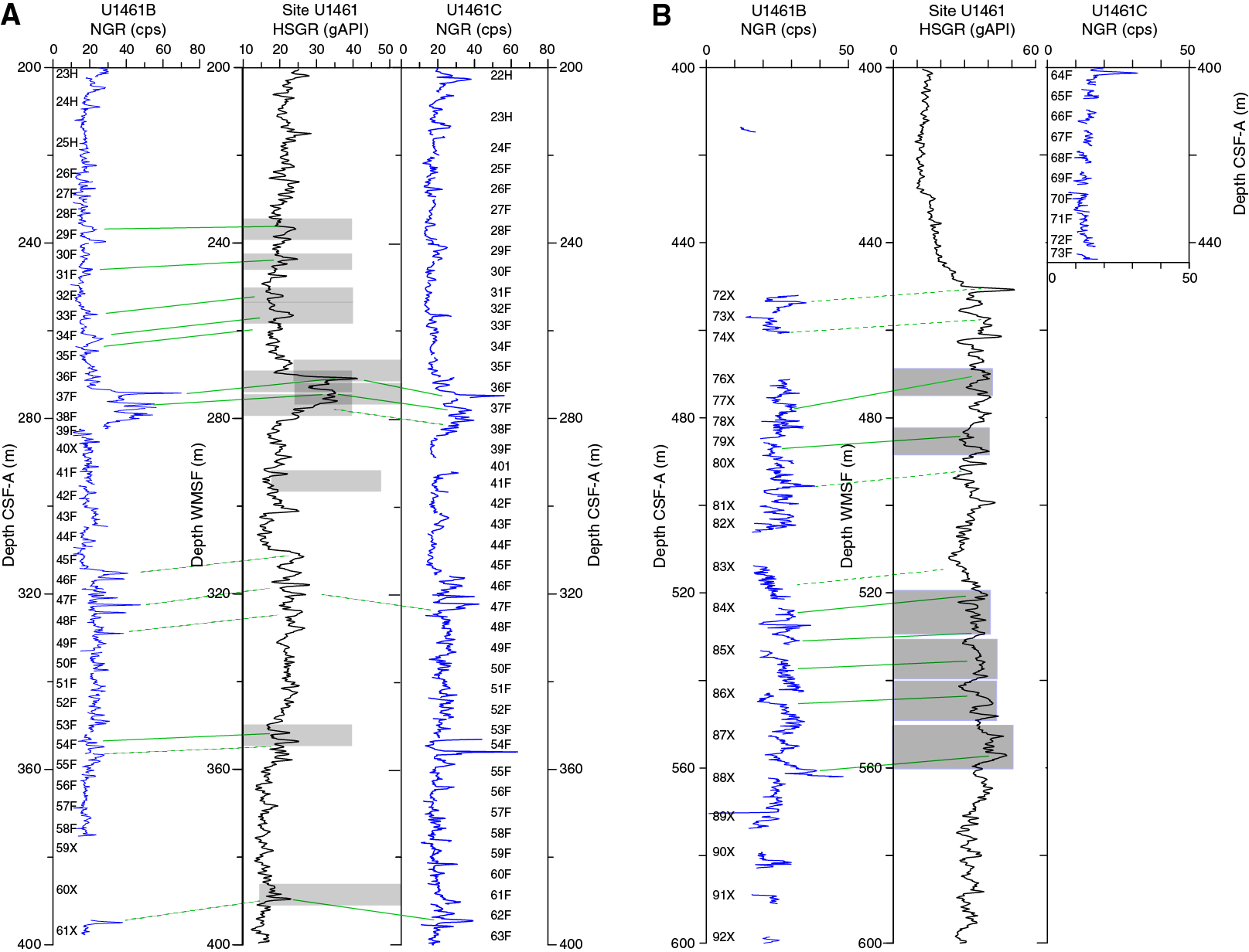
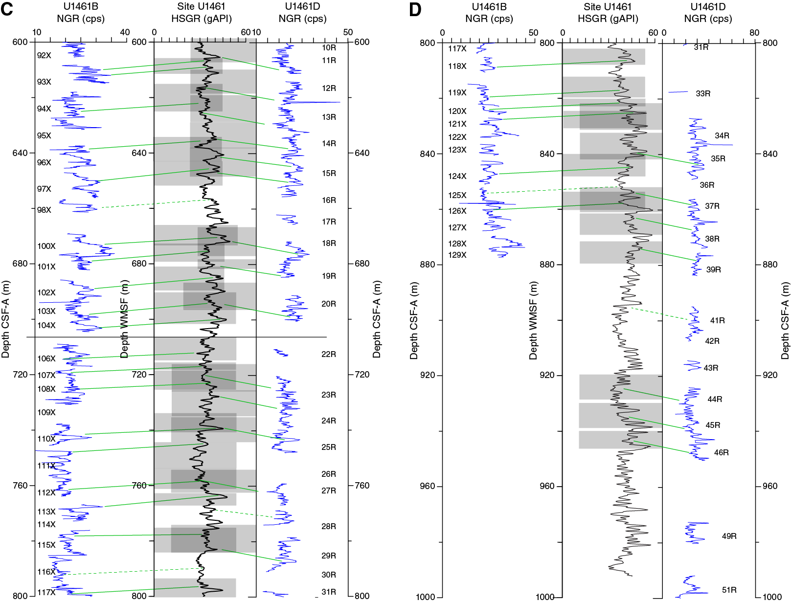
Figure F46. Comparison between NGR measured on Hole U1461B and U1461C cores with Hole U1461D wireline gamma log.
Although recovery was variable in both Holes U1461B and U1461D, well-developed trends in both MS and NGR allowed correlation deeper than 565 m CSF-A (see Physical properties). A correlation between Cores 356-U1461B-126X through 81X and 356-U1461D-61R through 10R (Table T17) bridges, as much as possible, gaps in recovery in Holes U1461B and U1461D. For example, Core 356-U1461B-93X bridges the gap between Cores 356-U1461D-11R and 12R. Where recovery was higher, tie points provide more certain correlations. For example, the tie point at ~720 m CSF-A, between Cores 356-U1461B-107X and 356-U1461D-23R, provides a point of correlation for the high-recovery interval shallower than 720 m CSF-A in Hole U1461B (Cores 356-U1461B-104X through 107X) and deeper than 720 m CSF-A (Cores 356-U1461D-23R through 25R). Holes U1461B and U1461D can be correlated this way to the base of Hole U1461B (Core 356-U1461B-126X), which is found at the same stratigraphic level as Core 356-U1461D-39R. The only significant interval with low recovery in both holes is found between 661 and 669 m CSF-A (Cores 356-U1461C-99X and 356-U1461D-17R through 18R).
Table T17. Correlations between Holes U1461B and U1461D. Download table in .csv format.
Construction of a splice (to produce CCSF-D)
A splice was created for the upper 239.4 m CSF-A in Hole U1461A, 235.4 m CSF-A in Hole U1461B, and 239.0 m CSF-A in Hole U1461C (these depths are all equivalent to 276.6 m CCSF-A in the composite or correlation) (Table T15; Figure F41). The splice was based on the cores shown in Figure F44. Patterns in NGR variation and/or MS were used to align the cores in the individual holes, but construction of a continuous spliced record requires discrete tie points in each core. Because unequivocal tie points were not always available, some uncertainty about correlation between cores was introduced. There was also a level of subjectivity in selection of the exact location of tie points, even though the patterns of peaks may be similar. For example, the tie point between Cores 356-U1461A-22H and 356-U1461B-19H can, in theory, be placed anywhere between 178 and 181 m CCSF-A (Figure F43).
Uncertain correlations from 40 to 55 m CSF-A (Cores 356-U1461A-7H-10X and 356-U1461B-6F through 7F) break the stratigraphic continuity established at the mudline with Core 356-U1461C-1H (Figures F41, F43, F44). Cores 356-U1461B-6H and 356-U1461C-6H could be correlated within this interval, and because recovery was most continuous in Hole U1461C, it was decided to append Core 356-U1461C-7H below 356-U1461C-6H (Figure F41B) to continue the formation of a splice. Strong correlations such as those around 72 m CCSF-A (Cores 356-U1461B-9H and 356-U1461C-7H) allowed reestablishment of a confident correlation below this level (Figures F41B, F43, F44). The correlation weakens at 276.6 m CCSF-A, so the splice was not continued beyond 276.6 m CCSF-A (Table T15; Figure F41E).
Note that the CCSF-D scale rigorously applies only to the spliced interval. Intervals outside the splice, although available with CCSF-A depth assignments, should not be expected to correlate precisely with fine-scale details within the splice or within other holes because of variation in the relative spacing of features in different holes. Such apparent depth differences of specific features may also reflect coring artifacts or fine-scale spatial variations in sediment accumulation and preservation at and below the seafloor.
Correlation of core to wireline
Hole U1461D was logged and the wireline gamma log (HSGR) compared to core-based NGR data from Holes U1461B–U1461D. Correlation between 200 and ~240 m CSF-A is limited by low-amplitude variation in the NGR signal (Figure F46A). Strong ties exist between Hole U1461B and the wireline to ~280 m CSF-A with weaker ties to 460 m CSF-A (Figure F46A–F46B). The correlation improves again at ~480 m CSF-A and ~525–560 m CSF-A (Figure F46B). Hole U1461D was drilled down with only spot coring (Figure F46C), so correlations are based on Hole U1461B through ~600 m CSF-A in Hole U1461D. From ~600 to ~850 m CSF-A (near the base of Hole U1461B), correlations are generally strong (Figure F46C–F46D). Core recovery is not sufficient to generate a splice, but it is possible to generate relatively continuous records using the wireline data as a guide.
Hole and site summaries (sedimentation rates)
A summary of the relationship between NGR and color reflectance b* (see Physical properties), biostratigraphic, lithostratigraphic (see Biostratigraphy and micropaleontology and Lithostratigraphy), and magnetostratigraphic (see Paleomagnetism) data, plus sedimentation rates calculated from biostratigraphic datums (see Biostratigraphy and micropaleontology), is presented graphically for Holes U1461A–U1461D (Figures F47, F48, F49, F50) and for Site U1461 (Figure F51). Sedimentation rates were calculated assuming a linear sedimentation rate between datums (in centimeters per thousand years and using the CSF-A depth scale).
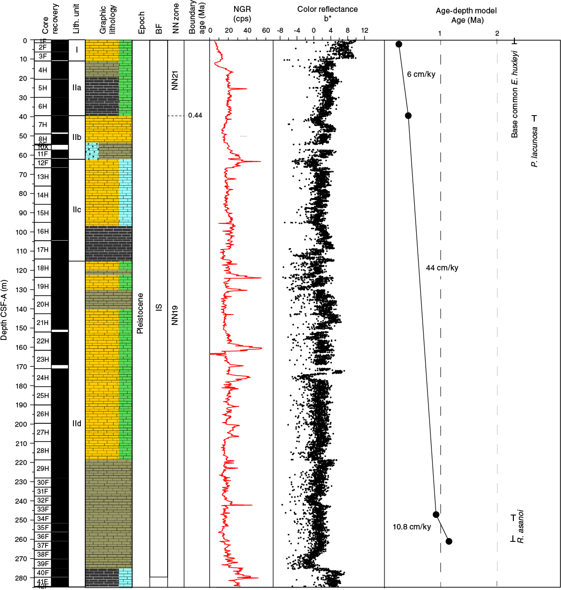
Figure F47. Hole U1461A lithology summary with NGR and color reflectance b*.

Figure F48. Hole U1461B lithology summary with NGR and color reflectance b*.
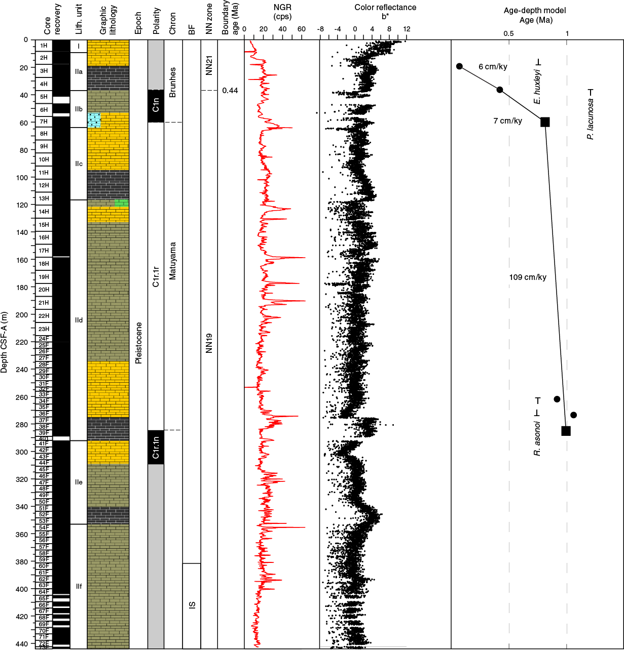
Figure F49. Hole U1461C lithology summary with NGR and color reflectance b*.
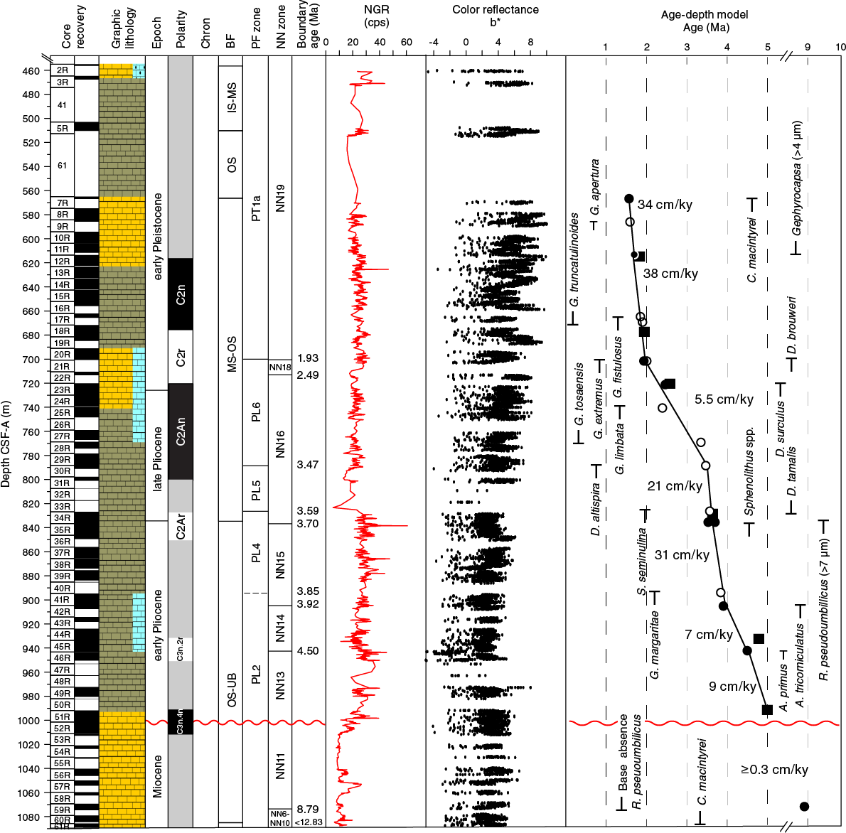
Figure F50. Hole U1461D lithology summary with NGR and color reflectance b*.

Figure F51. Site U1461 lithology summary with NGR and Hole U1461D wireline HSGR.
Although biostratigraphic and magnetostratigraphic data were not collected from all cores in each hole, trends are clear across the holes. Sedimentation rates are highest in the Late Pleistocene (43 cm/ky from 1 to 0.44 Ma; Zone NN19; 240–30 m CSF-A) and lowest in the latest Pleistocene (6 cm/ky from ~0.44 to 0 Ma) (Figures F47, F48, F49, F50).
Hole U1461D cored to Miocene-aged sediments (Figure F50). Few datums are present in this Miocene interval with poor microfossil preservation (see Biostratigraphy and micropaleontology), but sedimentation rates are estimated to be very low (<1 cm/ky). An unconformity, determined on the basis of a lithologic break in the core catcher of Core 356-U1461D-51R, is associated with a magnetic normal conditionally interpreted as Chron C3n.4n (4.997 Ma, see Paleomagnetism). This places the unconformity between ~9 Ma (the base of the absence of calcareous nannofossil R. pseudoumbilicus [8.79 Ma]; see Biostratigraphy and micropaleontology) and 5 Ma.
Early Pliocene sedimentation rates are moderate (7–9 cm/ky) in Zone NN13 and NN14 intervals in Hole U1461D (Figure F50). A more detailed biostratigraphic investigation was conducted on the upper Pliocene sediments in Hole U1461B (see Biostratigraphy and micropaleontology), and sedimentation rates therefore differ between Holes U1461B and U1461D (Figures F48, F50). Nonetheless, the rates show a similar pattern of moderate sedimentation rates (16–31 cm/ky) reducing to ~5 cm/ky around the Pliocene/Pleistocene boundary and dramatically increasing around the Zone PL6/Pt1a and NN18/NN19 boundaries (Figures F48, F50). The reduced sedimentation rate in the Pliocene is associated with channelized flow and transport from shallower shelf regions (see Biostratigraphy and micropaleontology and Lithostratigraphy), and the rapid early Pleistocene increase is associated with sandy gravity flows (see Biostratigraphy and micropaleontology and Lithostratigraphy), suggesting destabilization of the slope around the Pliocene/Pleistocene boundary.
Another interval of reduced sedimentation rates (8 cm/ky) around 1 Ma associated with R. asanoi datums (Hole U1461B) (Figure F48) is followed by rates of 43–44 cm/ky in Holes U1461A and U1461B. The inferred position of the Brunhes/Matuyama boundary in Hole U1461C results in even higher rates (109 cm/ky) in that hole (Figure F49). These high sedimentation rates continue through to the latest Pleistocene (0.44 Ma, based on the top of P. lacunosa; see Biostratigraphy and micropaleontology), when rates drop to ~6 cm/ky.
A graphic summary (Figure F51) was generated for Site U1461 that includes NGR measured on core and total gamma radiation from wireline logging in Hole U1461D. Biostratigraphic datums were selected for the site summary figure to show the general biostratigraphic pattern and were used to determine sedimentation rates for the site as a whole. The site summary figure does not provide the level of detail found in the hole summary figures, nor does it illustrate the differences found, for example, in datum levels or lithostratigraphy between the holes. Overall, sedimentation rates are low in the Miocene, across the unconformity, and into the early Pliocene. Sedimentation rates more than double in Zone NN15 and decrease to around 8 cm/ky around the Zone Pl4/Pl5 boundary. Rates are very high in the Pleistocene and are associated with gravity flows. Rates reduce significantly in the latest Pleistocene (0.44 Ma) but are still well above average sedimentation rates in the deep sea.
References
Chaisson, W.P., and Pearson, P.N., 1997. Planktonic foraminifer biostratigraphy at Site 925: middle Miocene–Pleistocene. In Shackleton, N.J., Curry, W.B., Richter, C., and Bralower, T.J. (Eds.), Proceedings of the Ocean Drilling Program, Scientific Results, 154: College Station, TX (Ocean Drilling Program), 3–31. http://dx.doi.org/10.2973/odp.proc.sr.154.104.1997
Dickinson, J.A., Wallace, M.W., Holdgate, G.R., Daniels, J., Gallagher, S.J., and Thomas, L., 2001. Neogene tectonics in SE Australia: implications for petroleum systems. The APPEA Journal, 41(1):37–52.
Dickinson, J.A., Wallace, M.W., Holdgate, G.R., Gallagher, S.J., and Thomas, L., 2002. Origin and timing of the Miocene–Pliocene unconformity in southeast Australia. Journal of Sedimentary Research, 72(2):288–303. http://dx.doi.org/10.1306/082701720288
Gallagher, S.J., Fulthorpe, C.S., Bogus, K., Auer, G., Baranwal, S., Castañeda, I.S., Christensen, B.A., De Vleeschouwer, D., Franco, D.R., Groeneveld, J., Gurnis, M., Haller, C., He, Y., Henderiks, J., Himmler, T., Ishiwa, T., Iwatani, H., Jatiningrum, R.S., Kominz, M.A., Korpanty, C.A., Lee, E.Y., Levin, E., Mamo, B.L., McGregor, H.V., McHugh, C.M., Petrick, B.F., Potts, D.C., Rastegar Lari, A., Renema, W., Reuning, L., Takayanagi, H., and Zhang, W., 2017. Expedition 356 methods. In Gallagher, S.J., Fulthorpe, C.S., Bogus, K., and the Expedition 356 Scientists, Indonesian Throughflow. Proceedings of the International Ocean Discovery Program, 356: College Station, TX (International Ocean Discovery Program). http://dx.doi.org/10.14379/iodp.proc.356.102.2017
Gallagher, S.J., Wallace, M.W., Hoiles, P.W., and Southwood, J.M., 2014. Seismic and stratigraphic evidence for reef expansion and onset of aridity on the northwest shelf of Australia during the Pleistocene. Marine and Petroleum Geology, 57:470–481. http://dx.doi.org/10.1016/j.marpetgeo.2014.06.011
Gallagher, S.J., Wallace, M.W., Li, C.L., Kinna, B., Bye, J.T., Akimoto, K., and Torii, M., 2009. Neogene history of the West Pacific Warm Pool, Kuroshio and Leeuwin Currents. Paleoceanography, 24(1):PA1206. http://dx.doi.org/10.1029/2008PA001660
Gradstein, F.M., Ogg, J.G., Schmitz, M.D., and Ogg, G.M. (Eds.), 2012. The Geological Time Scale 2012: Amsterdam (Elsevier).
Hemleben, C., Spindler, M., and Anderson, O.R., 1989. Modern Planktonic Foraminifera: Berlin (Springer-Verlag).
James, N.P., Bone, Y., Kyser, T.K., Dix, G.R., and Collins, L.B., 2004. The importance of changing oceanography in controlling late Quaternary carbonate sedimentation on a high-energy, tropical, oceanic ramp: north-western Australia. Sedimentology, 51(6):1179–1205. http://dx.doi.org/10.1111/j.1365-3091.2004.00666.x
Jones, H.A., 1973. Marine Geology of the Northwest Australian Continental Shelf. Bureau of Mineral Resources, Geology and Geophysics, Australia (Australian Government Publishing Service), 136. http://www.ga.gov.au/corporate_data/104/Bull_136.pdf
Lisiecki, L.E., and Raymo, M.E., 2005. A Pliocene–Pleistocene stack of 57 globally distributed benthic δ18O records. Paleoceanography, 20(1):PA1003. http://dx.doi.org/10.1029/2004PA001071
Lumsden, D.N., 1979. Discrepancy between thin section and X-ray estimates of dolomite in limestone. Journal of Sedimentary Petrology, 49(2):429–436. http://dx.doi.org/10.1306/212F7761-2B24-11D7-8648000102C1865D
O’Brien, G.W., and Heggie, D.T., 1989. Hydrocarbon gases in seafloor sediments, Otway and Gippsland shelfs: implications for petroleum exploration. The APEA Journal, 29:96–113.
Saito, T., Thompson, P.R., and Breger, D., 1981. Systematic Index of Recent and Pleistocene Planktonic Foraminifera: Tokyo (University of Tokyo).
Shackleton, N.J., Baldauf, J.G., Flores, J.-A., Iwai, M., Moore, T.C., Jr., Raffi, I., and Vincent, E., 1995. Biostratigraphic summary for Leg 138. In Pisias, N.G., Mayer, L.A., Janecek, T.R., Palmer-Julson, A., and van Andel, T.H. (Eds.), Proceedings of the Ocean Drilling Program, Scientific Results, 138: College Station, TX (Ocean Drilling Program), 517–536. http://dx.doi.org/10.2973/odp.proc.sr.138.127.1995
Spooner, M.I., De Deckker, P., Barrows, T.T., and Fifield, L.K., 2011. The behaviour of the Leeuwin Current offshore NW Australia during the last five glacial–interglacial cycles. Global and Planetary Change, 75(3–4):119–132. http://dx.doi.org/10.1016/j.gloplacha.2010.10.015
van der Kaars, S., and De Deckker, P., 2003. Pollen distribution in marine surface sediments offshore Western Australia. Review of Palaeobotany and Palynology, 124(1–2):113–129. http://dx.doi.org/10.1016/S0034-6667(02)00250-6
van Hinsbergen, D.J.J., Kouwenhoven, T.J., and van der Zwaan, G.J., 2005. Paleobathymetry in the backstripping procedure: correction for oxygenation effects on depth estimates. Palaeogeography, Palaeoclimatology, Palaeoecology, 221(3–4):245–265. http://dx.doi.org/10.1016/j.palaeo.2005.02.013
Wade, B.S., Pearson, P.N., Berggren, W.A., and Pälike, H., 2011. Review and revision of Cenozoic tropical planktonic foraminiferal biostratigraphy and calibration to the geomagnetic polarity and astronomical time scale. Earth-Science Reviews, 104(1–3):111–142. http://dx.doi.org/10.1016/j.earscirev.2010.09.003
Young, J.R., 1998. Neogene. In Bown, P.R. (Ed.), Calcareous Nannofossil Biostratigraphy: Dordrecht, The Netherlands (Kluwer Academic Publishing), 225–265.
1 Gallagher, S.J., Fulthorpe, C.S., Bogus, K., Auer, G., Baranwal, S., Castañeda, I.S., Christensen, B.A., De Vleeschouwer, D., Franco, D.R., Groeneveld, J., Gurnis, M., Haller, C., He, Y., Henderiks, J., Himmler, T., Ishiwa, T., Iwatani, H., Jatiningrum, R.S., Kominz, M.A., Korpanty, C.A., Lee, E.Y., Levin, E., Mamo, B.L., McGregor, H.V., McHugh, C.M., Petrick, B.F., Potts, D.C., Rastegar Lari, A., Renema, W., Reuning, L., Takayanagi, H., and Zhang, W., 2017. Site U1461. In Gallagher, S.J., Fulthorpe, C.S., Bogus, K., and the Expedition 356 Scientists, Indonesian Throughflow. Proceedings of the International Ocean Discovery Program, 356: College Station, TX (International Ocean Discovery Program). http://dx.doi.org/10.14379/iodp.proc.356.106.2017
- F1. Map of the northwest shelf showing major basins and location of modern and “fossil” reefs.
- F2. Bathymetric map showing the seafloor around Sites U1461 and U1462.
- F3. Multichannel seismic profile across Site U1461.
- F4. Lithostratigraphic summary, Holes U1461A–U1461D.
- F5. Smear slide summary, Holes U1461B–U1461D.
- F6. Representative smear slide photomicrographs of each unit.
- F7. Unlithified cream mudstone with abundant macrofossils and peloids, Site U1461.
- F8. Packstone and wackestone.
- F9. Boundary between Subunit IIc and Subunit IId.
- F10. Packstone, grainstone, and wackestone.
- F11. Lithified wackestone with common bioturbation, small benthic foraminifers, disseminated pyrite, and pyrite nodules, Hole U1461D.
- F12. Unit IV mudstone and sand-sized grain beds with bioturbation, Hole U1461D.
- F13. Calcareous nannofossils from upper 30 m of Holes U1461A and U1461C and deepest cored interval in Hole U1461D.
- F14. Calcareous nannofossils, Site U1461.
- F15. Depth ranges of calcareous nannofossil age markers.
- F16. Planktonic foraminifer abundance, Site U1461.
- F17. Typical preservation states of planktonic foraminifers, Site U1461.
- F18. Range of occurrence of planktonic foraminiferal marker species for the early Pleistocene–Pliocene interval, Holes U1461B and U1461D.
- F19. Planktonic foraminiferal age markers, Holes U1461A and U1461B.
- F20. Dominant benthic foraminiferal species and trends, Site U1461. This figure is available in an oversized format.
- F21. Benthic foraminifer diversity and benthic percentage of total foraminifers, Site U1461.
- F22. Hydrocarbons in headspace gases, Site U1461.
- F23. Alkalinity, pH, salinity, sodium, chloride, and sodium to chloride ratio, Site U1461.
- F24. Major constituents of interstitial water geochemistry, Site U1461.
- F25. Minor element interstitial water geochemistry, Site U1461.
- F26. Bulk sediment geochemistry, Site U1461.
- F27. Magnetostratigraphic data set, Holes U1461B and U1461C.
- F28. Magnetostratigraphic data set, Hole U1461D.
- F29. IRM acquisition curves for 8 discrete samples from Hole U1461B and their respective backfield IRM curves.
- F30. AF demagnetization results for 3 discrete samples, Hole U1461C.
- F31. WRMSL MS, drift-corrected SHMSL MSP, and NGR results, Site U1461.
- F32. MS results, Site U1461.
- F33. P-wave velocity, penetrometer, and shear strength results, Site U1461.
- F34. Bulk density, grain density, and porosity, Site U1461.
- F35. Reflectance spectroscopy and colorimetry, Site U1461.
- F36. A. APCT-3 in situ temperature. B. Thermal conductivity. C. Thermal resistance vs. temperature. D. Thermal conductivity.
- F37. HSGR, NGR, and elemental U, Th, and K concentrations.
- F38. Magnetic susceptibility measured by triple combo, SHMSL MSP, and elemental K estimated from HSGR spectra.
- F39. Hole U1461D diameter measured by triple combo and bulk density, porosity, and mud resistivity.
- F40. Hole U1461D diameter and sonic velocities from Site U1461 discrete measurements and Hole U1461D wireline.
- F41. NGR data for the continuous splice interval in Holes U1461A–U1461C together with the final splice record.
- F42. Drilling to recover coring gaps, Holes U1461B–U1461D.
- F43. Correlation between Holes U1461A, U1461B, and U1461C from 0 to 240 m CCSF-A, based on NGR data.
- F44. Cores used to develop correlations between Holes U1461A, U1461B, and U1461C from 0 to 280 m CSF-A.
- F45. Correlation between Holes U1461A, U1461B, and U1461C from 240 to 340 m CCSF-A, based on NGR data.
- F46. Comparison between NGR measured on Hole U1461B and U1461C cores with Hole U1461D wireline gamma log.
- F47. Hole U1461A lithology summary with NGR and color reflectance b*.
- F48. Hole U1461B lithology summary with NGR and color reflectance b*.
- F49. Hole U1461C lithology summary with NGR and color reflectance b*.
- F50. Hole U1461D lithology summary with NGR and color reflectance b*.
- F51. Site U1461 lithology summary with NGR and Hole U1461D wireline HSGR.
- T1. Operations summary, Site U1461.
- T2. Site U1461 core summary.
- T3. Lithostratigraphic unit summary, Site U1461.
- T4. Thin section samples, Site U1461.
- T5. Semiquantitative XRD analysis of dominant mineral phases, Site U1461.
- T6. Calcareous nannofossil and planktonic foraminifer datums, Site U1461.
- T7. Calcareous nannofossil abundance and range charts, Site U1461.
- T8. Occurrence of main genera and species of benthic and planktonic foraminifers and additional bioclasts and minerals, Site U1461.
- T9. Planktonic foraminifer presence, abundance, and preservation at Site U1461.
- T10. Planktonic foraminifer abundance, Site U1461.
- T11. Benthic foraminifer abundance, Site U1461.
- T12. Headspace gas contents, Site U1461.
- T13. XRD analysis results for magnetic mineralogy content for two discrete samples, Hole U1461B.
- T14. Polarity intervals and interpreted correlations, Site U1461.
- T15. Splice tie point table, Holes U1461A–U1461C.
- T16. Affine table, Holes U1461A–U1461C to 240 m CCSF-A.
- T17. Correlations between Holes U1461B and U1461D.