Früh-Green, G.L., Orcutt, B.N., Green, S.L., Cotterill, C., and the Expedition 357 Scientists
Proceedings of the International Ocean Discovery Program Volume 357
publications.iodp.org
doi:10.14379/iodp.proc.357.104.2017

Central sites1
G.L. Früh-Green, B.N. Orcutt, S.L. Green, C. Cotterill, S. Morgan, N. Akizawa, G. Bayrakci, J.-H. Behrmann, C. Boschi, W.J. Brazelton, M. Cannat, K.G. Dunkel, J. Escartin, M. Harris, E. Herrero-Bervera, K. Hesse, B.E. John, S.Q. Lang, M.D. Lilley, H.-Q. Liu, L.E. Mayhew, A.M. McCaig, B. Menez, Y. Morono, M. Quéméneur, S. Rouméjon, A. Sandaruwan Ratnayake, M.O. Schrenk, E.M. Schwarzenbach, K.I. Twing, D. Weis, S.A. Whattam, M. Williams, and R. Zhao2
Keywords: International Ocean Discovery Program, IODP, RRS James Cook, Expedition 357, Site M0069, Site M0072, Site M0076, seabed drills, RD2, MeBo, Atlantis Massif, Atlantis Fracture Zone, Mid-Atlantic Ridge, Lost City hydrothermal field, serpentinization, detachment faulting, oceanic core complex, hydrogen, methane, deep biosphere, carbon cycling, carbon sequestration, contamination tracer testing
MS 357-104: Published 4 February 2017
Operations
During Expedition 357, cores were recovered from three sites in the central area of Atlantis Massif: Sites M0069, M0072, and M0076 (Figure F1; Table T1). Newly acquired multibeam data, combined with preexisting data sets, were evaluated prior to each site to guide the drill teams with regard to anticipated seabed conditions and slope.
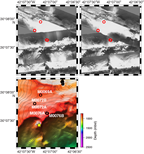
Figure F1. DSL120 sonar imagery and 50 m resolution multibeam bathymetry, Sites M0069, M0072 and M0076.
Table T1. Central sites hole summary. Download table in .csv format.
Site M0069
Cores were recovered from one hole at proposal Site M0069 (proposed Site AM-06), with an average site recovery of 74.76%. The water depth was 850.90 m with no tidal range. The total time spent on station was 2.04 days.
Hole M0069A
The RSS James Cook arrived on station at Site M0069 and settled into dynamic positioning (DP) mode at 0915 h on 6 November 2015. The conductivity, temperature, and depth (CTD) sensor package was deployed at 0922 h. At 1006 h, the CTD was 1.7 m off the bottom, and the first three Niskin bottles were fired. Two further Niskin bottles were fired on the way up, with a final one near the surface (see Table T5 in the Expedition 357 summary chapter [Früh-Green et al., 2017c]). The CTD was recovered on deck at 1038 h on 6 November.
At 1201 h, Meeresboden-Bohrgerät 70 (MeBo) drill deployment began. A full systems check was performed at ≈100 m water depth at 1304 h, but at 1337 h we found a hydraulic leak on the umbilical winch. After investigation, the deployment was continued, but further leaking from the umbilical winch led to the decision to abort the dive at 1425 h. The MeBo was recovered to the deck and was secure by 1530 h. The British Geological Survey RockDrill2 (RD2) was prepared for deployment because the predicted weather would put the swell outside the operational range for relaunching the MeBo.
At 2002 h, the RD2 was deployed, stopping for a full systems check at ≈300 m water depth. At 2111 h, the bridge requested the RD2 be stopped while they checked out a problem with GPS2. The RD2 held ≈40 m off seafloor for 30 min before continuing to the seafloor. Coring operations commenced at 2204 h. Coring continued steadily for 10 core runs; runs were completed at 2218 h on 6 November; 0057, 0510, 0726, 1113, 1413, 1705, 1921, and 2205 h on 7 November; and 0249 h on 8 November. Core Run 11 commenced at 0448 h. However, a technical problem with the gate valve resulted in the reduction of flushing down the borehole. The drill rods became stuck, and the drill string, including core Barrel 11, was lost in the hole after attempts to free the rods were unsuccessful. The RD2 was recovered on deck by 0800 h on 8 November.
During recovery, the Niskin bottles on the drill were triggered but did not close, and thus they remained open at the top until about 40 min after the drill was recovered. It was surmised that, because the bottoms of the bottles were sealed, the trip through the water column would result in minimal mixing and loss of bottom water. Indeed, later analysis of these samples showed significantly elevated H2 and CH4 concentrations. Additionally, as soon as the drill was recovered, a ship’s CTD cast was conducted over the drill site to retrieve postdrilling fluid samples for geochemistry and microbiological analyses. The CTD was deployed at 0853 h. At 0933 h, the CTD was 2.1 m off the bottom, and four Niskin bottles were fired. No other bottles were fired mid–water column or near surface, and the CTD was recovered on deck at 0955 h. The vessel departed station immediately on recovery of the CTD on deck.
In summary, 10 coring attempts were made in Hole M0069A to a maximum depth of 16.44 m with 74.76% recovery.
Site M0072
Cores were recovered from two holes at Site M0072 (proposed Site AM-01A), with an average site recovery of 53.29%. The water depth was 820.30 m with no tidal range. Two additional CTD casts were linked to this site (Holes M0072X and M0072Z) (see Table T5 in the Expedition 357 summary chapter [Früh-Green et al., 2017c]). The first was conducted over the Atlantis Fracture Zone at a water depth of ≈4244 m. The second was conducted in close proximity to Lost City at a water depth of ≈850 m. The total time spent on station was 2.16 days.
Hole M0072A
At 0532 h on 10 November 2015, the vessel began the transit to Site M0072 from Site M0071. By 0610 h, the vessel was on DP mode and the ship’s CTD was prepared for deployment. By 0723 h, the CTD cast was complete, having reached ≈1.8 m off the seafloor. Three Niskin bottles were fired near the seafloor, two mid–water column, and one near the surface (see Table T5 in the Expedition 357 summary chapter [Früh-Green et al., 2017c]).
By 0736 h, the ship was settled into DP mode, centered over the port-side deployment position for the RD2, and the drill was prepared for launch. The RD2 was deployed at 1010 h. At 1045 h, following mid–water column checks, it was discovered that the drill-mounted CTD sensor package had not been started. However, due to the ability to start the sensor remotely, the deployment continued, and at 1114 h the drill was positioned on the seafloor. Coring operations commenced at 1129 h, with the first core run completed by 1252 h. The second core run commenced at 1418 h. However, this run was aborted at 1438 h after consultation with the Co-Chief Scientists when it was discovered that a borehole plug had not been loaded onto the drill. The RD2 was recovered to deck by 1535 h. The two core barrels were unloaded, and the drill was readied for redeployment.
In summary, two coring attempts were made in Hole M0072A to a maximum depth of 2.23 m with 39.10% recovery.
Hole M0072B
At 1642 h on 10 November 2015, the RD2 was deployed in Hole M0072B. The drill was on the seafloor at 1708 h, and coring commenced at 1717 h. Hole M0072A was visible ≈1 m away under the skid of the RD2. The first three core runs were completed at 1815, 2053, and 2319 h. On recovery, however, the third barrel stuck in the bottom-hole assembly (BHA) and remained stuck after attempts to remove it by flushing and rotating the drill rods. The rod and BHA were tripped with the barrel still inside, and a new BHA was deployed at 0229 h on 11 November. After discussion, it was decided to ream back down to the depth reached by Run 3 (5.10 m) and then open-hole past the problem area (believed to be caused by talc), and coring recommenced at 6 m. During this process, a sharp increase in torque was observed at the depth where the third barrel had become stuck.
Coring continued throughout 11 November with high torque observed again at 8.93 m, resulting in a short core run of only 1.28 m. The barrel of core Run 7 became stuck at 8.98 m but was recovered after flushing. At 0411 h on 12 November, it was noted that the umbilical had become twisted, possibly due to the influence of an increasing sea swell, causing disruption to the controls of the hydraulic systems and the onboard cameras. It was requested that the vessel move under DP, spinning about the drill position in an attempt to untwist the umbilical. It was initially believed that this had been successful, and the RD2 maintained position for 30 min to ensure communications were stable. However, communications were again lost, and the decision was made to recover the RD2 at 0535 h. It was decided not to attempt logging the hole with unstable communications to the subsea drill controller, but the Niskin bottles were fired at 0740 h and the packer was installed by 0805 h. By 0900 h, the RD2 was on deck and secure. The umbilical was damaged and needed retermination, requiring at least 12 h of work.
At 0830 h the Master of the Vessel decided that the sea state was becoming excessive for deployment of either drill, so at 0900 h the vessel departed the site to continue a multibeam survey across Sites M0070 and M0074.
In summary, eight coring attempts were made in Hole M0072B to a maximum depth of 12.43 m with 52.22% recovery.
Site M0076
Cores were recovered from two holes at Site M0076 (proposed Site AM-11A), with an average site recovery of 66.44%. The water depth was 768.00 m with no tidal range. The total time spent on station was 2.37 days.
Hole M0076A
The vessel arrived at Site M0076 at 1020 h on 15 November 2015 and settled into DP mode. RD2 predive checks were still ongoing at the time of arrival, and deployment was delayed until 1339 h. Coring operations began at 1456 h with rapid penetration to 1.72 mbsf (end of core Run 1) by 1523 h. A hydraulic leak on the headshift terminated the hole early, and the RD2 was recovered on deck by 1606 h. No Niskin bottles were fired under instruction from the Co-Chief Scientist on shift.
The MeBo was still being repaired following damage to the base plate and leg on a previous dive, so the RD2 was rapidly turned around and redeployed in Hole M0076B.
In summary, one coring attempt was made in Hole M0076A to a maximum depth of 1.72 m with 23.26% recovery.
Hole M0076B
The RD2 was redeployed at Site M0076 at 1731 h on 15 November 2015. After initially landing on the seafloor at 1812 h, the drill had to be repositioned because of a high slope angle caused by landing unevenly on cobbles/boulders. The RD2 finally settled on the seafloor at 2012 h after three attempts to reposition both the drill and the umbilical. Coring operations commenced at 2040 h. Coring continued well until the end of core Run 2 (0005 h on 16 November), when high flush had to be run until 0133 h to free the stuck core barrel. A further eight core runs were recovered at 0615, 0933, 1336, 1706, and 2158 h on 16 November and 0132, 0429, and 0914 h on 17 November. At 14.75 m penetration, high backpressure on the flush pump was noted due to a “sticky” section. At the start of core Run 11 (16.31 m), there was difficulty reaming back to the base of the hole. The rods became stuck due to failure of the gate valve, resulting in no flush flow into the borehole. There was difficulty removing the overshot spear point from the overshot, which was ultimately achieved using the fishing tool, which is slightly shorter in length.
Prior to attempting to free the drill rods, two optical-acoustic-gamma (OAG) logging passes were completed through the pipe. The tool was deployed at 1314 h, and logging operations were completed by 1347 h. Various attempts were then made to free the drill rods, enabling the last rod to be unscrewed and recovered. An attempt was then made to connect the borehole plug to the drill rods still in the borehole, but it could not be connected. In attempting connection, the “J” connection at the top of the plug parted, resulting in the plug being unconnected both top and bottom. It was clamped in the breakout jaws but was lost during recovery of the drill. The RD2 was recovered on deck by 1656 h on 17 November.
During coring, repairs on the MeBo drill were made to port and starboard leg positions, a missing base plate, and the leg connection point. Some areas were cut away to allow for welding of new plates to strengthen the frame. On recovery, the RD2 crew required 12–14 h of maintenance to get the drill operational again. As both drills were unavailable for deployment, we decided to continue with the multibeam survey, imaging the conjugate margin of the Atlantis Massif complex. The vessel departed Site M0076 at 1900 h on 17 November.
In summary, 10 coring attempts were made in Hole M0076B to a maximum depth of 16.31 m with 71.79% recovery.
Lithology, alteration, and structure
Three sites were drilled in the central region of Atlantis Massif: from east to west, Sites M0076, M0069, and M0072 (Figure F2). These sites are the closest to the Lost City hydrothermal field and have highly heterogeneous lithologies, types of alteration, and extents of deformation. Intact lithologic contacts and alteration and deformation relationships (in addition to paleomagnetic results; see Paleomagnetism) suggest that coring at these central sites recovered in situ sequences of the shallow mantle and detachment fault zone at the top of Atlantis Massif (see VCDs in Core descriptions).
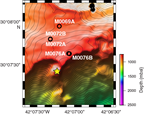
Figure F2. Location of Holes M0072A, M0072B, M0076A, M0076B, and M0069A.
Two holes were drilled at Site M0076: Hole M0076A is shallow (0.4 m of core), and Hole M0076B extends to 16.31 mbsf and recovered 11.71 m of core (Figure F3). Hole M0076B consists mostly of long intervals of coherent core dominated by serpentinized harzburgite and dunite with veins or intervals of partially to highly altered gabbroic material and moderately foliated talc-amphibole-chlorite schist, some of which contain clasts of metagabbro. The bottom of the hole (Cores 9R and 10R) also contains several carbonate veins. Core recovery in Hole M0076B was high, with an overall average recovery of 71% and recovery better than 88% in Cores 4R, 5R, 7R, and 8R.
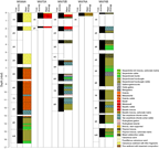
Figure F3. Lithologic summary for central holes.
The very top of both holes at Site M0076 is composed of calcareous sediment with basalt and some serpentinite fragments (Core 357-M0076B-1R). The very shallow Hole M0076A contains only this sedimentary material and a 5 cm thick interval of green mud with basalt and dolerite gravel.
Below the uppermost sediment interval in Hole M0076B, a principally coherent sequence is dominated by oxidized serpentinized harzburgite. The upper contact of this zone consists of talc-amphibole-chlorite schists that enclose small sections of metagabbro and oxidized serpentinized harzburgite. This zone transitions into coherent intervals of metagabbro and oxidized serpentinized harzburgite (bastite after orthopyroxene with grain sizes up to 10 mm, typically at a modal abundance of 10%–15%; Section 2R-1, Unit 3). Sections of mixed rubble (including fragments of serpentinized harzburgite, serpentinized dunite, metagabbro, and talc-amphibole-chlorite schist) with intervals of coherent serpentinites (Sections 3R-1 and 4R-1, Unit 1) overlie continuous sections of veined and serpentinized harzburgite alternating with serpentinized dunite (Section 4R-1, Unit 2, and below).
Hole M0072A is shallow (cored to 2.2 mbsf; recovered 0.87 m of core). Hole M0072B penetrated to 12.43 mbsf and recovered 6.5 m of core (Figure F3). Both holes have a shallow structural interval of sediment and rubble and two deeper intervals attributed to fault zones. Hole M0072B has long intervals of coherent core with three dominant lithologies: talc-amphibole-chlorite–bearing schist, serpentinized harzburgite with variably sheared veins of talc-amphibole material, and metagabbro and metadolerite, locally with reddish alteration. This style of localized red alteration was interpreted as rodingitization based on macroscopic observations, but the interpretation was not confirmed by thin sections.
Hole M0072A and the upper sections of Hole M0072B consist of surficial features including carbonate sands (with centimeter-scale subrounded basaltic lithic fragments), sedimentary basaltic breccias, and basaltic rubble (with rare oxide gabbro fragments observed in Hole M0072B). The sedimentary matrix in both holes contains foraminifers.
Four types of alteration were observed in Hole M0072B: serpentinization, talc-amphibole-chlorite metasomatism, oxidation, and rodingitization. Talc-amphibole-chlorite metasomatism is the most common alteration type and is present throughout. Serpentinization is the second most abundant alteration type and decreases in abundance below 8 mbsf. A complex fault zone was recovered below Core 5R. This zone shows alternating schistose, highly foliated regions of high strain hosting intervals of variably serpentinized peridotite with magmatic impregnations, and alteration to talc, tremolite, and chlorite. Several intervals of 5–15 cm thick rodingitized dolerite occur in this hole, with a strong mylonitic fabric observed locally (interval 6R-1, 18–24 cm).
Site M0069 consists of a single hole (Figure F3). Ten cores were drilled from Hole M0069A (one with no recovery), which penetrated 16.44 mbsf and recovered 12.29 m of core, constituting the overall highest percentage core recovery (74.76%) at any site. The upper four cores of the hole (1R–4R) recovered unconsolidated foraminiferal ooze and sands. The underlying cores (5R–10R) recovered mostly coherent hard rock with two dominant lithologies and distributions: amphibole-chlorite schist with intrusions and clasts of metadolerite in the upper part (Core 5R to Section 9R-1, 26 cm) and serpentinized and variably oxidized dunite within intervals of serpentinized harzburgite from Section 9R-1, 26 cm, to the bottom of the hole.
The mafic part of the hole comprises several intervals of strongly deformed schist, with a subhorizontal to moderately dipping foliation in the most deformed intervals. The lower contact of the mafic interval with serpentinized dunites is preserved and corresponds to a highly deformed interval with strong foliation and a pronounced reduction in grain sizes in the schist (interval 9R-1, 19–26 cm). This highly deformed interval may include intervals of gouge. The extent of deformation in the underlying serpentinized dunite and harzburgite is not clear from macroscopic observations. The lowermost 10 m of Hole M0069A shows three distinct structural units hosting several shear zones bounding intervals of dolerite and serpentinized dunite.
Site M0076
Rock types and igneous petrology
The predominant igneous rock type at Site M0076 is serpentinized porphyroclastic harzburgite with lesser mafic intervals (Figure F3). The upper sections of both holes are sedimentary basaltic breccias, with stratigraphy better preserved in Hole M0076A (including the overlying fossiliferous carbonate sediment; Section 357-M0076B-1R-1 contains mostly rubble). Below this uppermost interval of sediment, a principally coherent sequence of basement rocks is dominated by oxidized serpentinized harzburgite. The upper contact of this zone consists of talc-amphibole schists that enclose small sections of metagabbro and oxidized serpentinized harzburgite. In Section 357-M0076B-2R-1, Unit 3, a transition into coherent intervals of metagabbro and oxidized serpentinized harzburgite with bastite replacing orthopyroxene (grain size up to 10 mm), typically has a modal abundance of 10%–15%. Following sections of mixed rubble (including fragments of serpentinized harzburgite, serpentinized dunite, metagabbro, and talc-amphibole schists) with intervals of coherent serpentinites (Sections 3R-1 and 4R-1, Unit 1), Cores 5R and 6R are continuous sections of veined and altered alternating serpentinized harzburgites and serpentinized dunites (from Unit 2 downhole). The igneous petrology of Holes M0076A and M0076B is summarized on a core-by-core basis below (see VCDs in Core descriptions).
Hole M0076A
Hole M0076A consists of one core section with two lithologic units. Unit 1 comprises clasts of basalt, dolerite, and rare serpentinite set in a brown foraminifer-rich carbonate matrix. Clasts are poorly to moderately sorted. Unit 2 is mixed, unsorted breccia with subrounded clasts of basalt and dolerite as large as 2 cm. Basalts are slightly altered (≈30%), but primary olivine (5%), clinopyroxene (35%), and plagioclase (60%) remain (interval 1R-1, 28–31 cm). Plagioclase and clinopyroxene are fine to medium grained (maximum = 3 mm; average = 1.5 mm), and olivines are fine grained (maximum = 1 mm; average = 0.5 mm). Basalts are subophitic with subhedral tabular plagioclase crystals partially included in clinopyroxene. A sparsely vesicular (≈7%) aphyric subophitic basalt was observed under the microscope (Sample 1R-1, 28–31 cm) (Figure F4). Primary minerals include plagioclase (60%–65%), clinopyroxene (30%–35%), and olivine (3%), all of which are fine grained (≈1 mm). Approximately 20% of the primary assemblage has been altered to secondary hydrated minerals. Tabular plagioclase is euhedral to subhedral and partially enclosed by clinopyroxene.
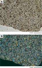
Figure F4. Aphyric vesicle-poor basalt. Coarse clinopyroxene partially includes tabular plagioclase grains.
Hole M0076B
Core 357-M0076B-1R consists of mafic rock–dominated carbonate breccia (Figure F5). Clasts comprise metagabbro, basalt, and one fragment of lithified breccia. The metagabbro includes dark cores (possibly olivine) surrounded by an unidentified white mineral (10% modal abundance), plagioclase (45% modal abundance), and clinopyroxene (45% modal abundance). The basalt contains 3%–4% vesicles (up to 1 mm) and is slightly oxidized along the edge. The fragment of carbonate breccia has a foraminifer-rich matrix and includes clasts of serpentinized harzburgite (bastites up to 5 mm × 10 mm; 20% modal abundance) and basalt in addition to talc schist clasts.

Figure F5. Alteration, Hole M0076B.
Section 2R-1 comprises four units. Unit 1 (0–46 cm) consists of talc-amphibole schist that contains fragments of gabbros and intervals defined by oxidized serpentinized harzburgite (at 19–25 and 44–46 cm). Unit 2 comprises metagabbro, and Unit 3 is oxidized serpentinized porphyroclastic harzburgite (15% modal abundance of relict pyroxene porphyroclasts, approximately 10 mm in diameter). The underlying unit is an interval of polymict breccia dominated by talc and serpentine clasts.
Core 3R contains mixed rubble (Unit 1), serpentinized harzburgite (Unit 2), and serpentinized dunite (Unit 3). The mixed rubble includes fragments of oxidized serpentinite, talc-amphibole schist, and coarse-grained metagabbro. The serpentinized dunite of Unit 3 is highly oxidized, preserves a well-developed mesh texture, and contains magnetite veins locally.
Core 4R is divided into three sections. Section 4R-1 contains two units. Unit 1 is composed of rubble of talc-amphibole-chlorite schist, locally oxidized serpentinite, and metagabbro. Unit 2 comprises oxidized serpentinized harzburgite (≈15% of 6–10 mm bastites) with infrequent magnetite veins. Sections 4R-2 and 4R-CC both contain slightly deformed oxidized serpentinized harzburgite that exhibits mesh texture. Four units are distinguished in Section 5R-1. Units 1 and 3 (below the microbiology sample at 0–36 cm) are highly serpentinized dunites with no evidence of primary mineral relics. A mesh texture is developed in the dunite but is highly sheared. The dunite is highly oxidized, particularly within the zones of mesh texture. These zones are separated by an interval of serpentinized harzburgite (Unit 3). Unit 4 (72–125 cm) comprises a metagabbro intrusion with intervals of serpentinized porphyroclastic harzburgite at 86–92, 101–114, and 121–125 cm. Section 5R-CC consists of fragments of serpentinized porphyroclastic harzburgite (approximately 20% bastites up to 7 mm) similar to that of Section 5R-1, Unit 2, described above (see VCDs in Core descriptions).
Core 6R contains serpentinized harzburgite infiltrated by melt intrusions. Bastites in the serpentinized harzburgite are 3–5 mm in diameter with an estimated modal abundance of 5%–10%.
Section 7R-1 also consists of serpentinized porphyroclastic harzburgite impregnated by several melt intrusions. Throughout most of the unit, bastites represent 5%–10% modally and are typically 1–6 mm in diameter. Melt intrusions were observed at 20 and 40 cm. Section 7R-CC contains clasts of oxidized serpentinized porphyroclastic serpentinites (bastites are 1–4 mm in diameter).
Section 8R-1 comprises serpentinized harzburgite (Units 1 and 3) punctuated by an interval of talc-amphibole schist (Unit 2). The uppermost half of Unit 1 contains rubble of predominantly porphyroclastic harzburgite followed by large coherent angular pieces of serpentinized harzburgite. Relict orthopyroxene (bastite; 1–8 mm) makes up 5%–10% of the modal mineralogy in the Unit 1 harzburgite. Unit 3 consists of oxidized serpentinized harzburgite (15% bastite, 2–5 mm in diameter).
Section 9R-1 consists of a single unit (Unit 1, 0–103 cm; microbiology sample at 34–64 cm) of highly oxidized serpentinized porphyroclastic harzburgite that exhibits fine-grained mesh texture. Orthopyroxene and/or bastite are as long as 3 mm with a modal abundance of ≈5%. The interval at 16–34 cm is more dunitic. Section 9R-CC is similar to Section 9R-1, consisting of serpentinized dunite with approximately 5% bastite (2–6 mm). The dunite is completely altered to serpentinite (interval 9R-1, 14–17 cm). It includes subrounded equant chromian spinel (1 mm × 2 mm) whose rim is completely altered to oxide (probably ferrite-chromite).
Section 10R-1 contains a series of relatively thin units of alternating serpentinized harzburgite and serpentinized dunite. Unit 1 (0–17 cm) comprises rubble of variably oxidized serpentinized harzburgite, and Unit 2 (17–44 cm) consists of variably fractured but intact serpentinized porphyroclastic harzburgite. Unit 3 consists of fragments of serpentinized harzburgite, whereas Unit 4 is composed of coherent serpentinized dunite that exhibits mesh texture. Unit 5 is weakly foliated porphyroclastic harzburgite with mesh texture crosscut by a network of carbonate veins. Unit 6 is fractured serpentinized dunite.
Alteration
In Hole M0076B, two main types of altered rocks are found: (1) oxidized and veined serpentinized harzburgites (Figure F6) and (2) metasomatic rocks dominated by talc, chlorite, and amphibole. The dominant alteration types are serpentinization, talc-amphibole-chlorite metasomatism, and oxidation (Figure F5). Furthermore, a few samples are cut by subvertical veins that are either highly altered magmatic veins (formed by magmatic fluids) or veins formed by high-temperature hydrothermal fluids (see below). Serpentinization and oxidation are the most common alteration types and are pervasive throughout the hole. Serpentinization and talc-amphibole-chlorite metasomatism alteration both show very high to total alteration, and oxidation intensity varies throughout the hole (Figure F5). Talc-amphibole-chlorite metasomatism is much more localized and found in several intervals of this hole.
Serpentinization
In hand specimen, serpentinized harzburgites and dunites are dark green to dark purple. Serpentinites are often no longer coherent but form very dense rubble (or moderately to highly fractured but coherent intervals). All ultramafic rocks are entirely serpentinized, and no primary minerals were found by thin section microscopy (see COREDESC in Supplementary material). Serpentinization of harzburgites and dunites resulted in the formation of macroscopic mesh to ribbon textures with bastites in the harzburgites. In thin section, the mesh texture is dominated by opaque mineral phases (most likely magnetite, in places locally oxidized to hematite) that form a network of veins and mesh cores characterized by fine-grained mineral aggregates (serpentine ± chlorite). Bastites are replaced by a fine-grained mixture of serpentine, chlorite, and amphibole.
Oxidation
Oxidation is pervasive throughout the entire core (Figure F5), giving serpentinites a dark purple color. The highest degrees of oxidation are observed in samples from the top of Section 357-M0076B-3R-1 in two pieces of highly oxidized serpentinized dunite (Figure F6). In these two samples, patches of orange color also reflect oxidation. In Section 9R-1 and 10R-1 serpentinites, oxidation decreases downhole, with the least oxidized samples recovered in Section 10R-1. In Section 9R-1, infiltration of oxidized fluids is exhibited by orange vein-cores in composite carbonate veins. Higher degrees of oxidation were observed as an approximately 0.5–1 mm wide zone along the contact between the serpentinites and the talc-amphibole-chlorite–rich zones and in the talc veins that crosscut the massive and banded green talc-amphibole-chlorite veins described below.
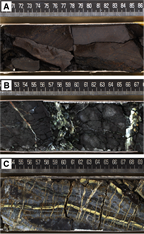
Figure F6. Intensely oxidized and serpentinized dunite pieces, carbonate and serpentine veined harzburgite, and subvertical veins cutting serpentinized peridotite.
Talc-amphibole-chlorite alteration
Talc-amphibole-chlorite alteration is localized and occurs within fault zones, occasionally forming a fine-grained gray zone around serpentinized harzburgite and dunite. These grayish rims are made up of talc, chlorite, and amphibole and increasingly consume the serpentine groundmass (Figure F7), producing a diffuse transition between oxidized serpentinite and talc-amphibole-chlorite schists. In thin section, amphibole is euhedral and coarse grained and forms along the contact with serpentinite, with a dominance of interlayered chlorite and talc inward, away from the contact. In hand specimen, the fine-grained intergrowth of chlorite and talc occasionally has a pale orange-brown color. This type of alteration is absent in samples recovered below Section 8R-1, 84 cm.
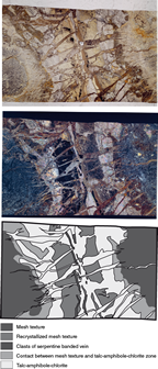
Figure F7. Metasomatic alteration of a possibly originally magmatic vein that subvertically crosscuts serpentinized harzburgite.
Veins and crosscutting relationships
Chlorite-amphibole-talc veins locally cut oxidized serpentinites. These veins are characterized by a composite to banded texture of green, white, and yellow-brown parallel veins, suggesting alternating chlorite-, talc-, and amphibole-rich bands (Figure F7). The veins are perpendicularly crosscut by lens-shaped talc veins, observable at the thin section scale. In Section 4R-1 (and possibly continued in 4R-CC), these subvertical veins are associated with an approximately 8 cm wide green, most likely chlorite-rich zone at the bottom of Section 4R-1. This zone also contains slightly paler green veins, which themselves are cut by a network of very fine black veins. A network of green, branched, most likely serpentine veins crosscuts the oxidized peridotites in Section 5R-1. Carbonate veins occur throughout the entire core but are more abundant in ultramafic rocks and most frequent in the lowest recovered sections (8R-1, 9R-1, and 10R-1). In interval 8R-1, 95–150 cm, oxidized harzburgite is crosscut by a set of white, parallel (almost horizontal) carbonate veins that cut dominantly subvertical green serpentine veins. Further downhole, veining occurs as a dense network of late carbonate veins that cut predating serpentine veins. Locally, up to 8 mm wide carbonate veins with orange cores cut the serpentinite mesh texture as planar veins.
Overprinting relationships
Microscopic observations suggest that serpentinization is the first stage of hydrothermal alteration, which is pervasive and complete throughout the entire hole. Talc-amphibole-chlorite–rich zones overprint the serpentinization texture, which is distinctly visible in thin sections. Serpentinization is also overprinted by pervasive oxidation.
Overview of alteration history
Hydrothermal alteration observed in cores from the three central sites reveals a similar general progression in alteration from serpentinization to talc-amphibole-chlorite metasomatism and later oxidation. However, as such systems remain highly dynamic, complex temporal and spatial relationships exist between the three main alteration types. In addition, alteration heterogeneities provide insight into the scales (<1 m to tens of meters) of the processes operating in the detachment fault. Carbonate precipitation is surprisingly not abundant in these holes, given their close proximity to the Lost City hydrothermal field.
Structure
Site M0076 was drilled closest to the Lost City hydrothermal field (Figure F2), above the slump scarps along the transform wall. It is located near the highest point of the striated surface (see Introduction in the Expedition 357 methods chapter [Früh-Green et al., 2017b]) and is the shallowest site drilled during Expedition 357 (water depth = 768 m). At the site, the striated surface dips gently ≈7° west parallel to the spreading direction and ≈10° north in the across-striation (spreading) direction. No late structures are resolved in the bathymetry disrupting the detachment fault surface at this location.
Two holes were drilled at this site: Hole M0076A to 1.72 mbsf and Hole M0076B to 16.3 mbsf (Figure F3). Hole M0076A recovered breccia with large angular basalt clasts (up to 10 cm) within a consolidated sedimentary matrix. This interval lies above a second one hosting smaller clasts that are either loose or embedded in an unconsolidated greenish matrix. Section 357-M0076B-1-CC comprises loose rubble, including vesicular basalt (see above). No constraint is available on the thickness of the upper structural interval at this hole because of low recovery over the uppermost ≈1.70 m drilled.
The remainder of Hole M0076B includes the following structural intervals:
- An upper complex fault zone from Section 2R-1, to 6R-1, 93 cm (1.7–10.6 mbsf). High-strain deformation is accommodated along schistose horizons rich in talc and/or tremolite that bound structurally continuous core sections of variably altered and veined peridotite (Figure F8). In this hole, schistose fault zones are typically shattered (likely induced by drilling), and no clear observations were made on the geometry of the fault zones and schistosity. Rubble sections of schistose material have thicknesses of several tens of centimeters up to 50 cm (top of Section 4R-1). Clasts of schistose material show folding, in addition to rare small clasts recording brittle deformation within the schistosity, dominated by dolerite.
- Ultramafic units, predominantly harzburgite with minor dunite, all heavily serpentinized. Veining is pervasive, with major subvertical veins crosscut by perpendicular, subhorizontal ones (see above) (Figure F9A). This veining geometry is observed in peridotite sections throughout Sections 3R-1, 4R-1, and 4R-2, which are separated by schistose fault intervals, suggesting general structural continuity. Some subvertical veins accommodate deformation, with weak- to moderate-intensity schistosity developed along their margins and cut by subhorizontal veins.
- Middle fault zone (interval 6R-1, 93–105 cm). The top of this interval is a narrow zone of high-intensity cataclastic deformation in dolerite (preserved in the core at 98–99 cm) that lies above a schistose zone of tremolite, and the bottom is a fine-grained breccia with clasts (submillimetric; 103–105 cm) embedded in an unconsolidated matrix (gouge?) (Figure F9A). X-ray diffraction (XRD) analysis from the gouge interval is dominated by talc with lesser chlorite and clinochrysotile (Figure F10). The zone is in contact with a deeper zone of high-intensity schistosity with deformed metagabbro clasts.
- Lower fault zone (interval 6R-1, 105 cm, to the bottom of the hole). As in the upper fault zone, this interval shows zones of schistose tremolite and/or talc with reworked clasts of variable size (from >10 cm to submillimetric; e.g., interval 8R-1, 60–80 cm). These schistose levels are less abundant and thinner than those above.
Figure F8. Amphibole- and talc-bearing shear zone.
Figure F9. High-intensity cataclastic deformation in dolerite, steeply dipping composite amphibole and chlorite (± talc) vein cutting serpentinized porphyroclastic harzburgite, and moderately dipping carbonate vein with oxidation cutting pyroxene-poor serpentinized dunite.
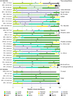
Figure F10. Mineral phases identified by bulk powder XRD analysis, Holes M0076B, M0072B, and M0069A.
Coherent units of harzburgite up to ≈1 m in length are heavily serpentinized and, as in the upper fault level, commonly show moderate to steeply dipping veins (Figure F9B, F9C). This lower peridotite unit is very fragile and shows heavy fracturing (oxidized) but is coherent and well preserved in the proximity of magmatic veins. No examples of schistose or cataclastic serpentinite were observed.
Site M0072
Rock types and igneous petrology
Site M0072 is located near the summit of the striated detachment fault surface (Figure F2). Hole M0072A (two cores) penetrated the uppermost 2.20 mbsf and recovered carbonate sand and sedimentary breccia consisting of clasts of basalt in a carbonate matrix (Figure F3). Hole M0072B (eight cores) penetrated to 12.43 mbsf and recovered the same sedimentary breccia as Hole M0072A, allowing this unit to be correlated across the two holes. Core 357-M0072B-4R had no recovery. In contrast to many other sites, Site M0072 is dominated by mafic lithologies as opposed to ultramafic ones; Hole M0072B also contains abundant rodingite intervals.
The upper sections of both holes consist of surficial features including carbonate sands (with centimeter-scale subrounded basaltic lithic fragments), sedimentary basaltic breccias, and basaltic rubble (with rare oxide gabbro fragments observed in Hole M0072B). Deeper intervals were cored in Hole M0072B, including rubble sections of mixed composition (metabasalt, metagabbro, and serpentinized harzburgite) that occur in Sections 3R-1 through 5R-1, Unit 1. These rubble sections overlie a principally continuous section of alternating talc-amphibole schists, rodingites, and serpentinized harzburgites (Section 5R-1, Unit 3, to the bottom of the hole in Section 8R-2). The igneous petrology of Holes M0072A and M0072B is summarized on a core-by-core basis below (see VCDs in Core descriptions).
Hole M0072A
Core 357-M0072A-1R consists of four units. Unit 1 comprises carbonate sand with 1–3 cm subrounded basalt fragments. The fragments are nonvesicular to sparsely vesicular and occasionally are oxidized along clast edges or contain a manganese crust. Core 1R, Units 2–4, is composed of basaltic breccia with a dark carbonate matrix (varying in degree of consolidation and fracturing).
Core 2R contains a number of rubble fragments of basalt and minor olivine basalt. The basalt is nonvesicular, has a microcrystalline matrix, and contains phenocrysts of plagioclase, olivine, and clinopyroxene.
Hole M0072B
Core 357-M0072B-1R consists of sedimentary basaltic breccia. The uppermost unit contains fossiliferous sand with rare fragments of angular basalt. This overlies basaltic breccia (Unit 2) and mixed rubble with fragments of basalt and breccia (Unit 3). Unit 2 includes two types of unconsolidated basalt fragments: Type 1 basalt has subangular to rounded vesicles (<1%) and an aphyric matrix, whereas Type 2 basalt has rounded vesicles (commonly infilled; i.e., amygdules) and a fine-grained matrix.
Core 2R is composed of basaltic rubble (interval 2R-1, 0–35 cm, Units 1 and 2) and oxide gabbro (interval 2R-1, 35–59 cm, Unit 3). Unit 1 basaltic rubble contains altered basalt and olivine basalt, and Unit 2 basaltic rubble consists of altered vesicular basalt fragments commonly infilled as amygdules. Unit 2 basalts also contain sulfides up to 2 mm in diameter. Unit 3 oxide gabbro is medium to coarse grained with ≈4–10 mm plagioclase, 4–6 mm clinopyroxene and oxides, and subophitic texture. Plagioclase and clinopyroxene make up ≈60% and ≈40% of the mode, respectively. Some variations are observed in thin section. The oxide gabbro in Sample 2R-1, 49–53 cm, contains 80% plagioclase (maximum = 7 mm; average = 4 mm), 15% clinopyroxene (0.5–3 mm), and 5% oxides (0.1–4 mm). Subhedral to anhedral plagioclase grains show subequant to tabular habits. Clinopyroxene and oxides are interstitial to plagioclase grains.
Core 3R contains mixed rubble with fragments of greenish gray metabasalt, metagabbro, and serpentinized harzburgite.
Core 5R consists of three units. Unit 1 comprises (mostly) well-rounded fragments of serpentinized harzburgite and metabasalt, and Unit 2 comprises moderately sorted talc-rich sediments with rounded basalt clasts. Unit 3 is talc-amphibole schist containing boudinaged dolerite fragments.
Core 6R is composed of six units of talc-amphibole schist, rodingites, dolerite, and dunite. Unit 1 (interval 6R-1, 0–12 cm) consists of rodingite and talc-amphibole schist fragments; the protolith of the rodingite is likely a gabbro. Unit 2 (interval 6R-1, 12–26 cm) is rodingitized gabbro. Unit 3 (interval 6R-1, 26–45 cm) is talc-amphibole schist but encompasses dolerite clasts. Unit 4 (interval 6R-1, 45–65 cm) consists of serpentinized dunite, whereas Unit 5 (interval 6R-1, 65–70 cm) comprises a thin interval of rodingitized gabbro. Unit 6 corresponds to a talc-amphibole-chlorite interval.
Core 7R is composed of five units including talc-amphibole-chlorite schist, serpentinized dunites, and harzburgites. Unit 1 consists of talc-amphibole-chlorite schist rubble and angular to rounded serpentinite clasts. Unit 2 contains serpentinized dunite with very fine grained mesh texture. Unit 3 is talc-amphibole-chlorite schist but contains two regions of brown alteration in intervals 7R-1, 37–40 and 53–59 cm, which possibly represent gabbro rodingitization. Unit 4 consists of mesh-textured serpentinized harzburgite with 1–4 mm long bastites (≈5% modal abundance). Unit 5 is talc-amphibole-chlorite schist that contains rodingitized gabbro. Section 7R-CC is composed of three angular pieces of partially rodingitized gabbro.
Core 8R contains rodingitized gabbro (Unit 1), serpentinized harzburgite (Unit 2), talc schist (Unit 3), and serpentinized porphyroclastic harzburgite with mesh texture (Section 8R-2, Unit 4). The rodingitized gabbro is medium to coarse grained and strongly foliated. The gabbro contains 3 mm plagioclase laths (≈20%) and 5 mm blocky clinopyroxene (30%). The talc schist (Unit 3) exhibits a thin (≈6 cm) interval of serpentinized harzburgite in interval 8R-1, 60–66 cm.
Alteration
Four types of alteration were observed in Hole M0072B: serpentinization, talc-amphibole-chlorite metasomatism, oxidation, and rodingitization (Figure F11). Talc-amphibole-chlorite metasomatism is the most common alteration type and is present throughout the hole. Serpentinization is the second most abundant alteration type and increases in abundance below 8 mbsf. Rodingitization is restricted to some mafic intervals between 7.7 and 9.9 mbsf. Oxidation developed at the top of the hole and between 9.1 and 9.7 mbsf.
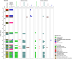
Figure F11. Alteration, Hole M0072B.
Alteration intensity increases overall in the uppermost 6 m of Hole M0072B from slightly altered to totally altered regardless of alteration type. Below 6 mbsf, the alteration intensity is predominantly classified as complete with discrete intervals of moderate alteration generally associated with rodingitization.
Above 6 mbsf, talc-amphibole-chlorite metasomatism is predominantly present as pervasive alteration, and below 6 mbsf, a combination of pervasive and localized alteration is observed. Serpentinization is pervasive.
Serpentinization
Serpentinization is predominantly dark green with some pale green to brown areas associated with areas of oxidation and is typically pervasive throughout the core. No primary minerals were observed, with the exception of relict Cr spinel. Textures range from mesh to hourglass. Magnetite is mainly concentrated in the mesh rims. Late serpentine veins are very common. In Hole M0072B, talc-amphibole-chlorite veins frequently crosscut areas of serpentinization, with a spacing on the order of tens of centimeters. The longest core interval displaying alteration dominated by serpentinization is a 25 cm interval in Section 8R-1.
Talc-amphibole-chlorite metasomatism
Talc-amphibole-chlorite metasomatism is pale green to white and occurs as both deformed schists and undeformed veins. Talc-amphibole-chlorite metasomatism overprinted the previous serpentinization and shows different assemblages and variable mineral abundances from one area to one other. An XRD profile through Section 357-M0072B-7R-1 shows alternation between a chlorite-rich zone (± amphibole), an amphibole-rich zone (± talc), and a talc-rich zone (± amphibole) (Figure F12). The chlorite-rich alteration, which is deep green, appears to always be spatially associated with mafic rocks. The metasomatic assemblage after serpentinite typically consists of sigmoidal areas made by larger broken amphibole crystals in a fine matrix of fine-grained acicular elongated amphibole (± chlorite) wrapped by a very fine grained foliated talc-rich groundmass.
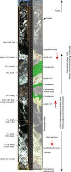
Figure F12. Complex shear zone showing a transition from static alteration to strain localization in alternating talc-, amphibole-, and chlorite-rich shear zones.
In Section 8R-1, the contacts between mafic and serpentinized ultramafic lithologies are preserved and appear to be zones of preferential alteration, as shown by the development of green and white metasomatic veins or zones (Figure F13). Green alteration (chlorite rich ± talc and amphibole) seems to follow the mafic unit that intruded the ultramafic protoliths subhorizontally, whereas talc-rich, white alteration is restricted to the serpentinites. The talc veins branch outward from the main zone of white alteration, and patches of whitish talc-rich areas extend into the rocks. These may mark preferential flow pathways. The final result is a complex network of metasomatic, fine-grained domains and veins exhibiting static to foliated patterns, leaving only limited areas that preserve the initial serpentinization textures.
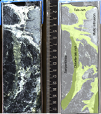
Figure F13. Magmatic intrusion into a fully serpentinized harzburgite. Late metasomatic alteration at the boundary of the mafic/ultramafic rocks produced a white and green talc-amphibole-chlorite assemblage that crosscuts the previous texture.
Oxidation
Oxidation in Hole M0072B was mainly recognized in thin sections and is restricted to late oxidation associated with metasomatic veins (Figure F14).
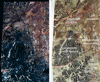
Figure F14. Serpentinite partially metasomatized to chlorite-amphibole-talc.
Rodingitization
Rodingitization occurs as pale brown to pinkish intervals (≈5 cm thick). Sections 357-M0072B-6R-1 and 7R-1 (Figure F12) show exceptional relationships between rodingite, talc ± amphibole-rich zones, and serpentinized harzburgite. Rodingites are the alteration products of gabbroic veins/lenses that intruded harzburgitic protoliths and are concentrated at the contact between the two lithologies. The altered mafic intrusions commonly show an external domain made mostly of chlorite (chlorite blackwall), whereas the light pink internal domain seems to be completely altered to a mix of chlorite and other fine-grained mineral assemblages that may include hydrogarnet.
Veins and crosscutting relationships
Hydrothermal veins are present throughout Hole M0072B and range in composition and distribution. Veins are generally 1–5 mm in width, predominantly with an irregular shape, and form branches or vein networks. Overall, the vein mineralogy is dominated by talc with chlorite/amphibole mixtures. Crosscutting vein relationships reveal that the multiple vein types do not show a consistent temporal evolution because talc veins are cut by amphibole veins but amphibole veins are also cut by talc veins.
Overprinting relationships and alteration history
Excluding the uppermost few meters of basaltic breccia and mafic rubble, Hole M0072B represents a harzburgite-dominated fault zone. Pervasive and complete serpentinization of harzburgite is overprinted by late Si-rich metasomatism that is variable between localized and pervasive and between static to foliated. Mafic intrusions are highlighted by chlorite blackwall domains that grade into talc-amphibole–rich areas close to the serpentinites. The irregularity of the crosscutting vein relationships emphasizes the dynamic multiphase nature of the system with similar composition of veins forming at multiple times. The alternation of the metasomatized and serpentinized domains, together with complex alteration textures, points to multiple pulses of Si-rich fluids into this part of the detachment fault.
Structure
Site M0072 is located near the summit of the striated detachment fault surface, ≈750 m north-northwest of the Lost City hydrothermal field (Figure F2). The site is on the flank of a gentle (10°N) slope that corresponds to the wall of a bathymetric striation (see Introduction in the Expedition 357 methods chapter [Früh-Green et al., 2017b]). No late structures that disrupt the detachment fault surface at this location are resolved in the bathymetry. Two holes were drilled at this site: Hole M0072A was cored to 2.2 mbsf and recovered 0.87 m; Hole M0072B penetrated to 12.43 and recovered 6.49 m of rock. Both holes have a shallow structural interval of sediment and rubble, and two deeper intervals attributed to fault zone were observed in Hole M0072B core.
The shallow structural interval comprises the entirety of Hole M0072A and Cores 357-M0072B-1R through 5R to ≈6.2 mbsf. The recovered cores in this interval record no contact relations and either are not in situ or are rubble on top of the basement. The shallow structural interval comprises unconsolidated sands and coarser sediment and includes the following, from top to bottom:
- Unconsolidated sand (0 to ≈0.4 m in both holes) containing angular clasts (primarily basalt) in a carbonate matrix with foraminifers. Consolidated breccia with an orange to gray matrix was recovered in interval 357-M0072A-1R-1, 40–50 cm. Below the breccia, the cores are composed of loose, unconsolidated rubble with no trace of sedimentary material or carbonate matrix. Clasts are dominated by basalt with minor gabbro and variably serpentinized peridotite. No contacts are preserved. This structural interval is considered not in situ.
- Fine-grained interval of cataclasis (possible fault gouge). Core 357-M0072B-5R was drilled through a 15 cm thick zone (interval 5R-1, 13–23 cm; 6–6.15 mbsf) of fine breccia with clasts ranging in size from a few millimeters to submillimeter (Figure F15). The matrix comprises unconsolidated greenish gray material and shows through-going structures (faint layering or lineaments over >2 cm), suggesting structural continuity without drilling disruption. Clasts are polymict, containing both dolerite and sheared talc-rich, variably schistose material similar to that found below.
- A complex fault zone recovered below Section 5R-1, 26 cm. This zone shows schistose, highly foliated regions of high strain with moderate to gentle dip (typically <45°) separating intervals of variably serpentinized peridotite (occasionally with magmatic impregnation). The serpentinite intervals commonly exhibit talc-amphibole-chlorite alteration. Several intervals of 5–15 cm thick rodingitized dolerite occur in this hole. In interval 6R-1, 18–24 cm, this rodingitized dolerite locally has a strong mylonitic fabric. Talc- and amphibole-rich schistose zones are continuous over core lengths of 13 to 34 cm (Figure F15) and often include cataclastically deformed dolerite and possibly serpentinized peridotite, with other rock types that were not identified. In the thicker schistose units, the fault zone shows an anastomosing structure with a complex set of crosscutting, small-scale shear zones and local folding of schistosity.

Figure F15. Fine-grained breccia in contact with a schistose talc-amphibole shear zone hosting brittlely deformed clasts of metadolerite.
Serpentinized peridotite within the shear zone shows structural continuity over core lengths of >50 cm and displays early deformation locally, including magmatic and later pale green or white metamorphic veining with talc and amphibole. The edges of the serpentinized blocks in contact with adjacent schistose fault zones show a gradient in the intensity of both alteration and deformation. Static alteration is observed away from main veins and at the edges of clasts; deformation gradually overprints this static alteration (Figure F12), forming schistose shear zones that locally display intense cataclasis of other rock types reworked in the fault zone (Figure F16). A feature in this core not seen at the eastern sites (M0068 and M0075) is strong deformation of talc-rich zones without clear localization between talc and tremolite in the core as a whole. Strongly deformed zones in serpentinite without talc or tremolite were not seen.
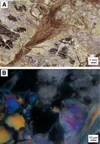
Figure F16. Serpentinized peridotite.
Site M0069
Rock types and igneous petrology
Site M0069 is the northernmost of the three central sites near the Lost City hydrothermal field (Figure F2). The site is located in a corrugation trough at the base of a north-facing slope with a relief of approximately 100 m (see Introduction in the Expedition 357 methods chapter [Früh-Green et al., 2017b]). Immediately north of the site is a steep mass-wasting scarp dissecting the corrugated surface. The Lost City hydrothermal field lies approximately 1 km due south along the transform wall.
A single hole (M0069A) was drilled at this site, penetrating 16.44 mbsf and recovering 12.29 m of rock in 10 cores (Figure F3) with a total overall recovery of 75% (one core with no recovery). Recovered rocks include serpentinized harzburgites, lesser serpentinized dunites, metagabbros, and metadolerites. The upper four cores of the hole contain carbonate sand transitioning into a loose rubble unit dominated by angular fragments of serpentinized harzburgite (Section 5R-1, Unit 1; fragments up to 4 cm). Coherent sections of serpentinized harzburgites (5% bastite after orthopyroxene) with observable mesh textures are observed below (Section 5R-1, Unit 2). A large portion of the remaining cores is dominated by metadolerite (Sections 5R-1, Unit 3, through 9R-1, Unit 2) and rubble sections. Metadolerite is generally aphyric and microcrystalline to fine grained (typically 0.2–0.5 mm); some sections exhibit larger clinopyroxene (up to 1 mm) and disseminated sulfides (<1 mm). The lower sections of the hole (9R-1, Unit 3, through 10R-3) contain alternating serpentinized harzburgites and serpentinized dunites; the harzburgites exhibit relict orthopyroxene (bastites; up to 10 mm and typically with a modal abundance of 10%–15%), and the dunites typically contain chromian spinel. The igneous petrology of Hole M0069A is summarized on a core-by-core basis below (see VCDs in Core descriptions).
Cores 1R, 2R, and 3R consist entirely of calcareous sand with rare small lithic fragments (<2 mm); Core 4R had no recovery.
Core 5R contains loose rubble with angular fragments (up to 4 cm) of mostly serpentinized harzburgite (Unit 1), a coherent piece of coarse-grained serpentinized harzburgite (Unit 2), and alternating metagabbro and metadolerite (Unit 3). In the coherent harzburgite, relict or altered orthopyroxene is granular and anhedral, ranging from 3 to 7 mm and occupying 5% of the mode. In regions of pale gray alteration, mesh texture is recognizable. Within Unit 3, a metagabbroic to metadoleritic unit (20–29 cm) is followed by intervals of metadolerite (29–35 cm) and metagabbro (35–49 cm). These intervals are followed by an interval of metadolerite at 62–83 cm and lighter toned dolerite at 83–115 cm. Approximately 1 mm diameter clinopyroxene and submillimeter disseminated sulfides were observed; plagioclase was not observed at the macroscale due to the small grain size. The metagabbro contains 1–3 mm subhedral, tabular plagioclase and 3–7 mm anhedral and granular clinopyroxene.
Core 6R consists of two sections. Section 6R-1 is divided into two units, the first containing metadolerite rubble and the second a coherent section of drilled metadolerite. Generally, dolerite is fine grained (e.g., 29–42 cm) with two localized (10 mm × 20 mm) patches of coarser material (37–42 cm, possible metagabbroic material). Dolerites in this section exhibit characteristic patchy alteration surrounding epidote veins. The underlying section (6R-2) also contains metadolerite crosscut by a network of epidote veinlets and altered locally to an assemblage dominated by chlorite.
Core 7R is divided into three units, the first (interval 7R-1, 0–8 cm) consisting of rubble dominated by dolerite and amphibole-chlorite schist. Unit 2 (interval 7R-1, 8–22 cm) consists of fractured talc-amphibole-chlorite schists. The last unit (interval 7R-1, 21–70 cm) is a metadolerite that is generally highly fractured with intact pieces of dolerite found mainly in interval 7R-1, 35–45 cm. Primary grain size increases in Section 7R-1 from 21 to 40 cm (away from the amphibole-chlorite schist); no chilled margin was observed at the macroscale.
Section 8R-1 is a more coherent section continuing from Core 7R, and it comprises fine-grained, fractured metadolerite overlying talc-amphibole-chlorite schists. The metadolerite is aphyric and microcrystalline (0.1–0.5 mm) and relatively fresh.
Core 9R consists of two sections. Section 9R-1 contains metadolerite rubble (Unit 1), polymict breccia (Unit 2), and serpentinized harzburgite (Unit 3). Section 9R-2 is characterized by alternating units of serpentinized harzburgite and serpentinized dunite and is divided into four units. Unit 1 (0–61 cm) comprises moderately oxidized serpentinized harzburgite with visible bastites. Unit 2 (61–77 cm) consists of oxidized serpentinized dunite with occasional mesh textures, but no recognizable orthopyroxene is apparent in the dunite. Some chromian spinels are found as aligned trains. Unit 3 is serpentinized harzburgite, as described above. Unit 4 is serpentinized dunite, as described above, but is less oxidized.
Core 10R consists of three sections. Sections 10R-1 and 10R-2 comprise serpentinized harzburgite, and Section 10R-3 comprises serpentinized dunite. Section 10R-1, Unit 1 (0–10 cm), is oxidized, mesh-textured serpentinized harzburgite rubble with protogranular orthopyroxene grains (≈5.5 mm; 15% modally). Section 10R-1, Unit 2, consists of fractured but intact serpentinized harzburgite. The serpentinized harzburgite of Section 10R-1, Unit 3, is pyroxene rich and contains protogranular and altered orthopyroxene (relict grains up to ≈10 mm with a modal abundance of 25%–30%; possibly with some minor clinopyroxene). Section 10R-2, Unit 1 (0–24 cm), consists of pyroxene-rich serpentinized harzburgites (25%–30% relict pyroxene, similar to Section 10R-1, Unit 3, above); Section 10R-2, Unit 2, consists of serpentinized dunite. Section 10R-3 also comprises serpentinized dunites, but they are less oxidized than those in Section 10R-2, Unit 2, and contain equant chromian spinel trains. The chromian spinel trains and disseminated patchy spinel-rich zones are only found in serpentinized dunite units (although isolated chromite is observed within serpentinized harzburgites). In places, chromian spinels may retain protolithic compositions based on microscopic observation (an example from a harzburgite is shown in Figure F17); chromite rims are typically altered into an opaque oxide (likely ferrite-chromite).
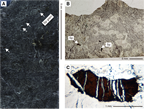
Figure F17. Serpentinized harzburgite with chromian spinel grain.
Alteration
The uppermost sections of Hole M0069A consist of sediment to 6.88 mbsf. Below this depth is small interval (5R-1, 12–20 cm) of metasomatized harzburgite, metadolerites with intervals of talc-amphibole-chlorite–rich sections, and entirely serpentinized harzburgites and dunites (Figure F3). A polymict breccia interval (13.12–13.29 mbsf) marks the transition between the metadolerites and serpentinites. Overall, four types of alteration were observed: hydrothermal alteration of dolerites and locally gabbros (classified as “other”) to metadolerites and metagabbros, respectively; serpentinization; oxidation; and talc-amphibole-chlorite metasomatism (Figure F18). Hydrothermal alteration of dolerites and gabbros includes three intervals of talc-amphibole-chlorite–rich rocks (7.01–7.08, 10.4–10.53, and 11.67–13.32 mbsf). Serpentinization dominates the ultramafic portion and is associated with extensive oxidation. Dolerites and gabbros are generally only slightly to moderately altered, whereas talc-amphibole-chlorite metasomatism in the mafic intervals is complete. The ultramafic piece at the top of the metadolerites is pervasively and highly metasomatized (predominantly to talc). Harzburgites and dunites are completely serpentinized and slightly oxidized. The distribution of dolerite and gabbro alteration is variable. The alteration types classified as “other” are usually pervasive, with the exception of one localized and one patchy occurrence of talc-amphibole-chlorite metasomatism (Figure F19A).

Figure F18. Alteration, Hole M0069A.
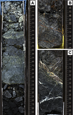
Figure F19. Amphibole-chlorite zone with large metadolerite clast, serpentinized dunite presenting a mesh to ribbon texture underlined by preferentially oriented magnetite concentrations along microfractures, and serpentinized dunite crosscut by multiple carbonate veins bordered by significant oxidation.
Hydrothermal alteration of dolerites and gabbros (classified as “other”)
Dolerites in the upper sections of Site M0069 cores have all undergone hydrothermal alteration. The dominant background alteration color is pale gray, and alteration halos and patches are pale brown to green. Throughout Sections 357-M0069A-5R-1 through 6R-2, irregular pale brown-green alteration patches are abundant and represent more than half the cut surface (Figure F20). In Sections 7R-1 to 8R-1, 93 cm, dolerite has pale gray background alteration. The abundance of brown halos dramatically decreases, and, where present, they are restricted to around veins or fractures. In thin section, the background alteration is dominated by chlorite and amphibole replacing plagioclase and clinopyroxene, respectively. Plagioclase is extensively replaced with ≈15% primary plagioclase remaining; however, clinopyroxene is totally replaced by amphibole. In thin section, alteration patches are dominated by chlorite and amphibole, as suggested by XRD analyses.
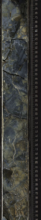
Figure F20. Alteration of pale, irregular, patchy alteration observed in metadolerites. Yellow-brown patches are chlorite rich and cut by epidote veins.
Serpentinization
Serpentinization is the dominant alteration type at the base of Hole M0069A in Sections 9R-1, 9R-2, and 10R-1. These sections comprise serpentinized harzburgite and dunite. Serpentinization is pervasive, and no primary minerals are preserved other than Cr-rich spinel. In hand samples, a well-recognizable mesh-to-ribbon texture was observed, reflected by networks defined by concentrations of magnetite along the mesh rims or parallel bands of magnetite, respectively (Figure F19B). Locally intense recrystallization of serpentine occurs along purple-black corridors. Serpentinized harzburgites are clearly distinguished from dunites based on the presence and abundance of bastites. In thin section, the serpentine-magnetite mesh texture to local ribbon texture is well preserved. Bastites mostly consist of chlorite and amphibole with local talc rims. Chlorite is also locally present as bands within the mesh texture and around spinel.
Oxidation
In Hole M0069A, oxidation is mostly restricted to the ultramafic units. Although metadolerites may be slightly oxidized, such alteration was not evident macroscopically. In serpentinites, it develops pervasively and more intensely along veins and fractures (Figure F19C), locally producing a halo that borders the veins. In addition, a few carbonate veins comprise an orange vein-core, suggesting the presence of iron hydroxides. The degree of oxidation ranges from slight to high and decreases with increasing depth. In the lowermost drill core, oxidation is almost entirely absent.
Talc-amphibole-chlorite metasomatism
Talc-amphibole-chlorite metasomatism is present in one interval in Hole M0069A (5R-1, 12–20 cm) where a serpentinized harzburgite is pervasively and very highly metasomatized to mostly talc. In addition, talc-amphibole-chlorite–rich zones are present in Sections 8R-1 and 9R-1 and are associated with localized horizons of intense deformation.
Veins and crosscutting relationships
Both metadolerites and serpentinites are highly veined. In dolerite, veins are yellow-brown and composed of epidote as determined by optical microscopy and XRD. They are typically localized within specific intervals and have a fine-grained yellow-brown halo composed of chlorite and epidote (Figure F20). In serpentinite, carbonate veins and serpentine veins are present. Local recrystallization of serpentine occurs, producing dark purple fine-grained bands that are cut by later carbonate veins. Carbonate veins are as wide as 8 mm and range from fine vein networks to planar veins. They range in vein structure from uniform to banded to composite with abundant Fe oxide–rich cores. In interval 10R-2, 20–27 cm, a 1.4 cm wide polycrystalline vein cuts the serpentinite. The vein mostly consists of carbonate with traces of chlorite and serpentine. Locally, the vein also contains remnants of magnetite-vein fragments.
Overprinting relationships and alteration history
Initial interpretation suggests that dolerites possibly intruded talc-amphibole-chlorite schists, overprinting the mineralogy and texture of the previous fault rocks but also producing a slightly brecciated contact between the mafic and ultramafic rocks. Complete serpentinization of the ultramafic rocks and high degrees of oxidation suggest that these serpentinites were exposed to extensive fluid circulation with late formation of carbonate veins. In contrast, the overlying metadolerites show patchy and localized alteration and lower degrees of oxidation.
Overview of mineralogy from XRD data
Samples for XRD analysis were taken from three different holes at each of the three central sites (Figure F10). The most commonly identified phases were secondary minerals, namely serpentine (mainly lizardite and [clino-]chrysotile), talc, amphibole, and chlorite. Chlorite is the dominant phase in Hole M0069A samples, sometimes occurring in proportions >90%. Chlorite is also dominant in many Hole M0072B samples, whereas Hole M0076B is dominated by talc and serpentine, where they are the most frequent and abundant (Table T2). In Holes M0072B and M0069A, significant amounts of talc were only detected in intervals 357-M0072B-7R-1, 74–90 cm, and 357-M0069A-5R-1, 18–19 cm. Amphibole was also frequently detected and occurs in significant proportions in Hole M0072B. Essentially no primary phases were detected in any of the samples analyzed. Carbonate occurs as a minor phase in some samples and is a major component of two shallow samples, one from Hole M0069A and one from Hole M0076B. Other minor phases detected include spinel, magnetite, hydrogarnet, clay, zeolites, Mn/Fe oxides, and hydroxides.
Table T2. X-ray diffraction results, Holes M0069A, M0072B, and M0076B. Download table in .csv format.
Structure
Structural features divide Hole M0069A into distinct structural intervals. The upper structural interval (0–6.5 mbsf; Sections 1R-1 through 4R-1) is composed of unlithified calcareous sediment (sand/ooze) with foraminifers and shows no internal structure. A single basaltic clast is found in Section 1R-1 at 0.85 mbsf.
The lowermost 10 m of core exhibits three distinct structural units hosting several shear zones bounding intervals of dolerite and serpentinized dunite (Figure F21).
Figure F21. Deformation and dolerite intrusion, Hole M0069A.
Structural Unit A
Structural Unit A is rubble (interval 5R-1, 0–20 cm). Clasts include serpentinized harzburgite (>5 cm) and smaller clasts of various compositions. Some clasts show weak foliation and may correspond to a shear zone at the top of the core. Below this rubble interval, the core is relatively coherent and comprises structural Units B and C.
Structural Unit B
Structural Unit B is a fault zone including deformed and altered doleritic intervals (interval 5R-1, 20 cm, to 9R-1, 26 cm; ≈6.9–13.3 mbsf). This structural unit includes highly schistose, coherent shear zones (interval 8R-1, 88–150 cm) with both consolidated and unconsolidated matrix material (interval 6R-1, 0–40 cm).
Structurally continuous intervals of dolerite are bound by shear zones or faults and show various types of alteration and deformation intensity. Dolerite often has pervasive epidote veining (interval 5R-1, 39–50 cm) of variable intensity but is always associated with moderate to intense cataclasis (Figure F21). Typically, coherent metadolerite intervals (30 and 130 cm thick) are bound above and below by intervals of breccia that may or may not include talc-tremolite-chlorite schist. Locally, subhorizontal foliation was observed; late thin faults and fractures cut the preexisting zone of cataclasis and veining. Cataclastically deformed dolerite is cohesive, likely cemented by secondary minerals. Breccias and schistose zones sometimes include clasts of dolerite from >10 cm to submillimetric in size. Importantly, this unit contains an intrusive contact between dolerite and fault rocks, showing that dolerite intrusion was synkinematic.
Core 6R contains fine-grained breccia with angular clasts in an unconsolidated matrix (interval 6R-1, 20–30 cm) (Figure F22). This breccia interval lies above a relatively undeformed but shattered (likely drilling induced) metadolerite. A second breccia interval is observed at the bottom of this structural unit in Core 7R, also showing a subhorizontal contact with fine-grained metadolerite but lacking epidote veins (likely a chilled margin). In Section 8R-1, dolerite exhibits a chilled margin against a steeply dipping amphibole-chlorite shear zone with a structural thickness of 2 cm (Figure F21). The chilled margin is irregular and locally disrupted by minor faulting, but the relationship is clear in hand specimen. Below the shear zone, coarse consolidated breccia is composed of rotated fault schist clasts, up to 5 cm in size, of variable intensity. These breccia clasts themselves host metadolerite clasts, showing a protracted history of intrusion and deformation of various styles. Below this ≈30 cm thick breccia interval lies a 5 cm thick zone of intense cataclasis (clast size = 1–5 mm) bound below by a sharp planar fault dipping 35°. Beneath this fault lies another interval of coarser breccia with a dark matrix, possibly intrusive doleritic material. This breccia is 12–15 cm thick and bounded by a sharp fault dipping at 15° above unconsolidated fragments of fault rock. This interval continues through Core 9R, where unconsolidated fragments overlie a 3 cm probable gouge zone, which in turn overlies schistose serpentinite with a subhorizontal but irregular contact. The schistose serpentinite marks the top of structural Unit C, which is otherwise unaffected by high strain zones.
Figure F22. Cataclasis of a chlorite-rich interval and no consistent foliation.
Structural Unit C
Structural Unit C is the deepest structural interval in Hole M0069A and is characterized by intensely serpentinized harzburgite (Sections 9R-1 through 10R-3) recovered in long, structurally coherent sections hosting intense fracture systems. It also includes a level of heavily fractured oxidized (black) serpentinized peridotite (interval 10R-1, 0–50 cm), similar to those observed in structural Unit C in Hole M0076B (Figure F9).
Basement structural Units A–C are likely in situ, as indicated by the subhorizontal schistosity and contacts associated with the shear and fault zones.
Bulk rock geochemistry
Bulk carbon analyses
As discussed in Bulk rock geochemistry in the Eastern sites chapter (Früh-Green et al., 2017a), the total carbon (TC), total inorganic carbon (TIC), and total organic carbon (TOC) contents of shipboard samples from all Expedition 357 sites were measured together during the Onshore Science Party and are reported in one table (see Table T3 in the Eastern sites chapter [Früh-Green et al., 2017a]). These results should be considered maximum concentrations and viewed with caution because samples were taken from existing thin section billet (TSB) residues.
Whole-rock major and trace elements
Whole-rock major elements and trace elements from central Sites M0069, M0072, and M0076 were run in batch with samples from all sites and are reported in common tables (measured major and trace elements are in Table T4, and normalized major elements are in Table T5, both in the Eastern sites chapter [Früh-Green et al., 2017a]).
Site M0069
Four samples from Hole M0069A were analyzed: two from Section 5R-1, and two from the deeper Core 10R (see Tables T4 and T5 in the Eastern sites chapter [Früh-Green et al., 2017a]). Lithologically, Core 5R samples are metadolerites (5R-1, 25.5–32 and 110–113 cm), and Core 10R samples include a serpentinized harzburgite (10R-1, 80–87 cm) and a serpentinized dunite (10R-3, 0–2.5 cm). The major element geochemical distinction between the two sections directly reflect lithologic differences, and geochemical characteristics of each lithologic group represented here are generally consistent with other sites.
The metadolerite samples show pronounced depletion in SiO2 with corresponding enrichment in Al2O3 and Fe2O3 relative to other rocks analyzed, which reflects the presence of chlorite as the major alteration mineral. The enrichment of metadolerites in P2O5 suggests a minor phosphate phase is likely present (e.g., apatite). Compared to the metadolerites in Core 5R, the serpentinized samples in Core 10R have lower TiO2, an order of magnitude lower Al2O3, significantly higher MgO, and lower Na2O. Ni and Cr concentrations are also significantly high in Core 10R serpentinite samples, with Cr of ≈3 wt% in the serpentinized dunite (Sample 10R-3, 0–2.5 cm), reflecting the presence of relict chromite. This sample also shows higher concentrations of Cu, Zn, and Co compared to other samples from the central sites. The Mg# of the samples from each core also differs as expected for the different lithologies and is consistent with samples at other sites: Mg# is 34 and 44 in the Core 5R metadolerites and 75 and 78 in the Core 10R serpentinized peridotites.
Depending on the core, Site M0069 samples vary in their trace element compositions, and among the central sites, they show the widest range of variations (between 0.1 to 10 times chondrite for the rare earth elements [REEs], except for Sample 10R-3, 0–2.5 cm (Figure F23). Notably, Core 10R samples have very strong positive Pb and Sr anomalies, whereas Core 5R samples have negative Pb and Sr anomalies (Figure F24). Furthermore, Core 5R metadolerites have Y concentrations 10 times higher than the deeper serpentinite samples of Core 10R, and Cr is significantly lower. Ni and Zr concentrations are also 10 times lower in the metadolerites, whereas Li, Sm, and Nd are enriched and U is depleted by a factor of about 0.01.
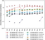
Figure F23. Chondrite-normalized REE plot, Holes M0069A and M0072B.
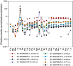
Figure F24. Primitive mantle–normalized extended trace element plot, Sites M0069, M0072, and M0076.
Site M0072
Site M0072 was drilled into the northern portion of the carbonate cap above the Lost City hydrothermal field. Whole-rock major element concentrations range widely in the four samples analyzed from Hole M0072B. SiO2 compositions vary from 38.6 to 50.6 wt% and reflect varying degrees of metasomatic talc-amphibole-chlorite overprinting (impregnated) serpentinized harzburgites. Similar variations were observed in other major oxide concentrations: Al2O3 varies from 0.03 to 0.14 wt%, TiO2 from 0.03 to 0.14 wt%, Fe2O3 from 3.4 to 9.9 wt%, MnO from 0.06 to 0.13 wt%, MgO from 26.1 to 37.6 wt%, CaO from 0.45 to 7.66 wt%, and Na2O from 0.09 to 0.35 wt% (see Figure F22 and Table T4, both in the Eastern sites chapter [Früh-Green et al., 2017a]). No samples contained measurable K2O, and P2O5 is low, ranging from 0 to 0.02 wt%. These samples lie in a relatively narrow Mg# range from 76 to 87, differing only slightly from the average of serpentinized harzburgite samples. Trace element systematics between these samples are very similar, with slight differences in overall enrichment and in particular enrichment in U (Figure F24). REE-normalized patterns are generally flat and vary between 1 to 5 times chondrite (Figure F23). On extended trace element diagrams, Site M0072 samples tend to have positive U and negative Nb anomalies (Figure F24).
The sample with the highest SiO2 (50.6 wt%), TiO2, Al2O3, and CaO and the lowest Fe2O3 and MgO is a talc-amphibolite-chlorite schist (Sample 5R-1, 37–38 cm) that has lower concentrations of lithophile elements (and also shows greater LREE depletion) than the three other Site M0072 samples but also displays a strong positive U anomaly (Figure F24) and exhibits generally very similar trace element systematics to the (impregnated) serpentinized harzburgites. Only Sample 8R-1, 76–77 cm (with lower Fe2O3 and higher CaO than the other Site M0072 serpentinized peridotites), lacks this characteristic enrichment in U. Ni ranges from 1252 to 3687 ppm at this site (see Figure F19 in the Eastern sites chapter [Früh-Green et al., 2017a]).
Site M0076
Site M0076 is the closest site to the Lost City hydrothermal vent field. One sample of serpentinized harzburgite (Sample 357-M0086A-7R-10, 81–83 cm) was analyzed for major and trace element composition. The Mg# of 80 for this sample is one of the highest of the shipboard suite of samples (see Table T4 in the Eastern sites chapter [Früh-Green et al., 2017a]). Like most serpentinite samples, the sample contains elevated Ni and Cr (2810 and 2420 ppm, respectively). It has small positive Pb and Sr anomalies, is enriched in Ba, and has a very strong positive U anomaly. It also has relatively low high field strength element (HFSE) abundances (Zr = 0.38 ppm; Hf = 0.1 ppm) and a very flat chondrite-normalized REE pattern with a small negative Ce anomaly (Figure F23).
Fluid chemistry
Inorganic and organic fluid chemistry
Cations and anions
As reported in detail in Fluid chemistry in the Eastern sites chapter (Früh-Green et al., 2017a), salinities, major elements, trace elements, and anions measured in fluid samples during the expedition had concentrations comparable to bottom seawater (see Tables T6, T7, T8, and T9 in the Eastern sites chapter [Früh-Green et al., 2017a]). There was no detectable sulfide or ammonia (see Tables T6 and T10 in the Eastern sites chapter [Früh-Green et al., 2017a]).
pH, alkalinity, and dissolved inorganic carbon stable carbon isotopic composition
As reported in detail in Fluid chemistry in the Eastern sites chapter (Früh-Green et al., 2017a), the alkalinities and pH of fluid samples were similar to background seawater at all sites (see Table T11 in the Eastern sites chapter [Früh-Green et al., 2017a]), with the exception of pore water from carbonate sands from one of the central site locations (see Figure F25 in the Eastern sites chapter [Früh-Green et al., 2017a]).
Volatile chemistry
As reported in detail in Fluid chemistry in the Eastern sites chapter (Früh-Green et al., 2017a), methane concentrations ranged from below detection limit to 48 µM, and hydrogen concentrations varied from trace levels to 323 µM (see Table T12 in the Eastern sites chapter [Früh-Green et al., 2017a]). Hot spots of hydrogen were observed over Sites M0068–M0072, and hot spots of methane were observed over Sites M0070–M0072 (see Figure F26 in the Eastern sites chapter [Früh-Green et al., 2017a]).
Microbiology
Samples collected
Following the procedure described in detail in Microbiology in the Expedition 357 methods chapter (Früh-Green et al., 2017b), whole-round core (WRC) samples were transferred to the cold room after they were photographed.
At Site M0069, five WRC samples (Sections 357-M0069A-4R-1, 5R-1, 7R-1, 9R-2, and 10R-1) were collected for microbiological studies (Table T3; see MBIOWRC in Supplementary material). These samples were divided into five unflamed frozen samples, three flamed frozen samples, four enrichment samples, two exterior perfluormethylcyclohexane (PFC) samples, two interior PFC samples, three exterior cell count samples, two interior cell count samples, and two single-cell analysis samples. Additional exterior cell count samples were taken at the top and bottom of Section 2R-1 and at the top of and adjacent to the microbiology whole-round sample from Section 5R-1.
Table T3. Whole-round cores collected for microbiological analysis, Sites M0069, M0072, and M0076. Download table in .csv format.
At Site M0072, seven WRC samples were collected for microbiological studies: two from Hole M0072A (Sections 1R-1 and 2R-1) and five from Hole M0072B (Sections 1R-1, 3R-1, 5R-1, 7R-1, and 8R-3) (Table T3; see MBIOWRC in Supplementary material). These samples were divided into seven unflamed frozen samples, five flamed frozen samples, five enrichment samples, six exterior PFC samples, four interior PFC samples, six gas analysis samples, five exterior cell count samples, four interior cell count samples, and four single-cell genomics analysis samples.
At Site M0076, five WRC samples (Sections 357-M0076B-3R-1, 5R-1, 7R-1, 9R-1, and 10R-1) were collected for microbiological studies (Table T3; see MBIOWRC in Supplementary material). These samples were divided into five unflamed frozen samples, four flamed frozen samples, four enrichment samples, seven exterior PFC samples, four interior PFC samples, four gas analyses samples, four exterior cell count samples, four interior cell count samples, and four single-cell analysis samples. Additional exterior cell count samples were taken at the top of Sections 3R-1, 5R-1, 7R-1, and 9R-1 and adjacent to microbiology whole-round samples from Sections 3R-1 and 5R-1.
Samples sent to Kochi Core Center (Japan) were immediately frozen at –80°C and then shipped under temperature-controlled conditions with constant temperature logging. There, WRC exteriors were cut away with a band saw system equipped in a clean booth and used for PFC tracer check (exterior), concentration and isotopic composition of TIC/TOC, vein analysis, in situ organic carbon and Fe mineral analysis, and trapped-gas analysis. The interior portions of the frozen samples were subjected to shore-based nucleic acid analyses and interior PFC, organic, and lipid analyses.
Liner fluid from the core barrels was collected from many cores from each site and was split for PFC, cell count, and organic acid analyses (Table T4).
Table T4. Core liner fluid samples for microbiological analyses, Sites M0069, M0072, and M0076. Download table in .csv format.
Contamination assessment with PFC tracer
Samples of liner fluid, sensor package Niskin bottles, and exterior and interior pieces of WRCs were collected to assess contamination by quantifying the concentration of PFC tracer added during drilling operations (see Microbiology in the Expedition 357 methods chapter [Früh-Green et al., 2017b]). Laboratory atmosphere blanks are also reported in Table T15 in the Eastern sites chapter [Früh-Green et al., 2017a] to define lower detection limits; these values varied throughout the expedition because of buildup of volatilized tracer in the shipboard laboratory. PFC concentrations for samples are reported in picograms PFC per cubic centimeter of sample, and laboratory blanks are reported as picograms PFC per milliliter air.
PFC delivery during drilling operations in all central site holes (M0069A, M0072A, M0072B, M0076A, and M0076B) was weak based on very low concentrations (<100 pg PFC/mL of sample) of tracer in the sensor package and liner fluid samples (see Table T15 in the Eastern sites chapter [Früh-Green et al., 2017a]). Exterior and interior WRC samples had comparably low levels of tracer.
Cell abundance determination
Cell abundance was determined shipboard by direct counting with an epifluorescence microscope (see Microbiology in the Expedition 357 methods chapter [Früh-Green et al., 2017b]). For shipboard analysis of select rock samples, flame-sterilized interior cell count samples were crushed into millimeter-sized grains, and then 3 cm3 was taken for fixation. Minimum quantification limits of the cell counting methods were determined by analysis of procedural negative controls and determined to be 48 cells/cm3.
In select samples from central Sites M0069 and M0072, cell abundance was very low, except in shallow (<1 mbsf) samples (Table T5). In the uppermost sediment sample of Hole M0069A (0.3 mbsf), cell density was ≈1 × 10⁵ cells/cm3. In the uppermost sample of Hole M0072A (0.3 mbsf), cell density was ≈1.1 × 10⁶ cells/cm3. Cell abundance was relatively high (7.3 × 10³ cells/cm3) for rock samples from 0.3 mbsf in this hole. At both sites, cell abundance decreased rapidly with depth. Below 7.0 mbsf in Hole M0069A, cell abundance did not exceed 4 × 10² cells/cm3. In Hole M0072B, cell abundance was around the limit of detection of 102 cells/cm3 below 0.5 mbsf. Cell abundance was not determined shipboard for Site M0076 samples because of time limitations; these samples will be measured in a shore-based laboratory.
Table T5. Microbial cell abundance counted on flame-sterilized interior piece of rock samples, Sites M0069 and M0072. Download table in .csv format.
Enrichment and incubation experiments
The growth and activity of microbial communities was studied in rock samples obtained during the expedition using a variety of culture-based approaches. Flame-sterilized pieces of rock material were ground to fine particles under anoxic conditions and distributed into the various incubation vessels (Table T3; see Microbiology in the Expedition 357 methods chapter [Früh-Green et al., 2017b]).
Samples were used in the following ways:
- To study the assimilation of stable isotope–labeled carbon and nitrogen compounds (Sections 357-M0069A-4R-1 and 5R-1, 357-M0072B-5R-1, and 357-M0076B-9R-1);
- To study the growth of microorganisms at elevated hydrostatic pressures (Sections 357-M0069A-4R-1 and 9R-2, 357-M0072B-7R-1, and 357-M0076B-3R-1);
- To evaluate the presence of hydrogenotrophic and/or methanogenic microorganisms, as well as heterotrophic microorganisms, under alkaline, anoxic conditions (Sections 357-M0069A-4R-1 and 9R-2, 357-M0072B-7R-1, and 357-M0076B-3R-1);
- To study the growth of microorganisms under sulfate-reducing conditions (Sections 357-M0069A-4R-1 and 9R-2, 357-M0072B-1R-1 and 7R-1, and M0076B-7R-1 and 3R-1); and
- To study the activities of microorganisms and extracellular enzymes (Sections 357-M0072B-3R-1 and M0076B-5R-1).
Water samples for microbiological analysis
Water from sensor package Niskin bottles and CTD rosette Niskin bottles was sampled for measurements of PFC, cell counts, and nucleic acids from Sites M0069, M0072, and M0076 (Tables T6, T7) and for many chemical measurements (see Water sampling and sensor package data in the Expedition 357 methods chapter [Früh-Green et al., 2017b]). Water samples from the CTD rosette were also obtained from two locations near Site M0072: Hole M0072X (over the Atlantis Fracture Zone) and Hole M0072Z (near Marker H of the Lost City hydrothermal field). Select water samples were used to quantify cell abundance in fluid samples (Table T8). Cell abundance had little variation with depth, ranging from 3.2 × 10⁴ cells/mL (sampled at 11.3 mbsl) to 7.8 × 10⁴ cells/mL (sampled at 293.3 mbsl).
Table T6. Water samples collected from sensor package Niskin bottles for microbiological analysis, Sites M0069, M0072, and M0076. Download table in .csv format.
Table T7. Water samples collected from CTD Rosette Niskin bottles for microbiological analyses, Sites M0069 and M0072. Download table in .csv format.
Table T8. Microbial cell abundance counted on water samples, Site M0069. Download table in .csv format.
Sensor package data
Mapping drill data onto the sensor plots for all sites was done graphically, and for records of approximately 1000 min, the potential errors are on the order of ±5 min.
Hole M0069A
The sensors started recording in Hole M0069A at 2107 h (UTC – 2 h) on 6 November 2015, and data are recorded in two files (Figure F25; Table T9). Overall, Hole M0069A exhibited no CH4 anomalies with a background maximum of 0.4 nM. Background values for pH were 8.8, and pH generally increased with depth, with steeper increases during drilling of the upper six cores. Water temperature varied from 9.10°C to 9.95°C, with no clear trends in variation associated with drilling conditions.
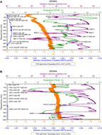
Figure F25. Sensor data, Hole M0069A.
Table T9. Sensor signal time log, Hole M0069A. Download table in .csv format.
Oxidation-reduction potential (ORP) signals during drilling were variable (Figure F25A). The ORP signal started dropping prior to the beginning of Core 1R, implying that fluids more reducing than seawater were emanating from this site. This first ORP excursion had two minima at 2216 and 2251 h. The first minimum occurred at about the time Core 1R was finished (penetration depth = 1720 mm), and the second happened during the switch from Core 1R to Core 2R. This excursion toward lower ORP values did not return to near-background values of about 340 mV until 0231 h, after the end of Core 2R at 3440 mm, at which time another ORP minimum started. Drilling of Core 2R stopped at 2346 h to add a new drill rod and restarted at 0013 h; however, the ORP signal does not seem to have been impacted in a significant way during this period.
The next major ORP minimum started at 0231 h between Cores 2R and 3R when the flush pump was not connected to the drill string. It reached a minimum at 0323 h, just prior to the beginning of Core 3R, and returned to background values at 0450 h. The implication is that the ORP signal reached a minimum during the period of nonflushing and was then diluted by the restart of flushing, resulting in the signal returning to near–bottom water values. Unfortunately, a gap in the RD2 drill data from 0414 to 0634 h means we are unable to definitively tie drilling activities to this ORP minimum or the next minimum at 0525 h. This latter minimum, however, occurred entirely during the period between the end of Core 3R (5160 mm) and the start of Core 4R when most likely the hole was not being flushed and formation fluid was seeping out of the hole with less dilution from bottom seawater.
The next ORP minimum started at 0640 h, was lowest at 0646 h just prior to the beginning of Core 4R, and approached background values at 0840 h, just after the start of Core 5R (6880 mm) when a new minimum began. This minimum lasted about 2.5 h and occurred entirely within the time of drilling Core 5R. At 0938 h, drilling was stopped to add a drill rod. Drilling recommenced at 0950 h, corresponding to the minimum ORP value. The ORP value steadily declined throughout the remaining time that Core 5R was being drilled, ending at 8600 mm.
The second sensor data file (Figure F25B) for this hole shows that two different mechanisms can result in ORP minima. Drilling of Core 8R started at 1759 h (11,320 mm). The first major ORP minimum started at 1743 h, reached a minimum at 1840 h, and rebounded to near-background values entirely within Core 8R. This particular core was straight drilling the entire time with no stops for adding a new drill rod; therefore, the hole was being flushed with bottom water the entire time. The flush rate started at 15 L/min, increased to 20 L/min at 1818 h, and increased again at 1849 h to 20 L/min, where it stayed for the remainder of the core, which ended at 1921 h (13,040 mm). Thus, this negative ORP excursion was the result of penetration into a more reducing horizon within the hole. Although variable flush rates might have influenced the shape of the peak, the strong negative excursion does not correlate with periods of flushing or no flushing, which appears to be the case with the next ORP minimum. The next ORP minimum started at 0017 h and was lowest at 0100 h, almost entirely within Core 10R, which started at 2322 h (14,720 mm). In this case, however, drilling stopped at 0010 h (15,234 mm) to add a drill rod and started again at 0102 h. Decreasing ORP values occurred during a period with no flushing, and once flushing resumed, ORP values immediately started to increase. In this case, it seems the lack of flushing produced the ORP excursion by allowing the more reducing formation fluids to be pumped past the sensors, and then the signal was diluted when flushing resumed. Core 10R ended at 0249 h (16,440 mm). It seems likely this same mechanism produced the ORP minimum centered at 0448 h, although a data gap between 0250 and 0440 h makes this conjecture less reliable than others. This excursion took place during the period when Core 11R was unsuccessfully attempted. The beginning of the excursion likely started during a period of no flushing because the drill never proceeded beyond 16,440 mm where Core 10R ended, so no new reducing horizons were encountered. Drilling of Core 11R started at 0440 h with a flush rate of 20 L/min that was maintained until drilling ceased at 0530 h. Flushing continued at 20 L/min until 0545 h when it was increased to 50 L/min for 5 min. Again, this anomaly appears to have started during a period of no flushing and was diluted away by flushing the hole. There are no drill data for the last ORP minimum at 0612 h.
Hole M0072A
Hole M0072A is a short two-core hole with no CH4 anomalies and only two negative ORP excursions (Figure F26; Table T10). CH4 steadily increased from about 0.2 nM at the start of drilling until the end of Core 1R, where it stabilized at 1.5 nM for the duration of drilling. The pH values increased downhole from 7.8 to 7.9. The first ORP excursion started at 1238 h, 1475 mm into Core 1R. The ORP minimum was at 1247 h (1627 mm), about 4 min before the completion of Core 1R (penetration depth = 1720 mm). The drill started turning at 1332 h and stopped at 1339 h. It is uncertain what occurred during this time, as the drill logs indicate that Core 2R started at 1418 h. The second ORP excursion started at 1339 h, reached a minimum at 1349 h prior to the start of Core 2R, and returned to background values at 1438 h at the end of Core 2R (2225 mm). There are no drill data from 1335 to 1414 h, so we can only speculate that this ORP minimum is the result of a lack of flushing while core barrels were being changed.
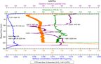
Figure F26. Sensor data, Hole M0072A.
Table T10. Sensor signal time log, Hole M0072A. Download table in .csv format.
Hole M0072B
The sensors started recording in Hole M0072B at 1652 h on 10 November 2015 (Table T11), with the data plotted in three files. In the first 300 min of sensor data (Figure F27A), CH4 background values ranged from 0.2 to 1.0 nM and there was a small CH4 peak (1.5 nM) centered at 1744 h (1461 mm) while drilling Core 1R. The most significant event during this period was the 11 nM CH4 signal centered at 2025 h while drilling Core 2R. This CH4 increase was accompanied by a negative excursion in ORP, which is indicative of more reducing fluids being flushed from the hole. The pH value gradually increased throughout this period, suggesting that formation fluids were being influenced by serpentinization.
Table T11. Sensor signal time log, Hole M0072B. Download table in .csv format.
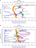

Figure F27. Sensor data, Hole M0072B.
In the next 900 min of the sensor data (Figure F27B), CH4 background values were near 1 nM and there were several small CH4 peaks, all accompanied by negative ORP signals. The small CH4 peak at 2254 h occurred prior to stopping drilling during Core 3R to add a drill rod and thus was not induced by this process. While drilling Core 4, the core barrel became stuck in the BHA, which necessitated that a new BHA be deployed. Additionally, the hole was reamed to 5160 mm and then open-hole drilled to 5985 mm. The CH4 peak at 0422 h occurred during this process, and the CH4 peak at 0626 h happened at the end of this process, when the hole would not have been flushed. There were also several ORP minima associated with Core 4R operations. The largest of the CH4 peaks (5.5 nM) occurred at 1129 h while drilling Core 6R (7990 mm) just after a new drill rod was added between 1103 and 1113 h. The pH value continued to slowly increase downhole during this period and exhibited a significant increase associated with the 1119 h CH4 peak. This peak was followed by the lowest ORP voltage (210 mV) seen during this period.
The final 1200 min of drilling at this hole (Figure F27C) produced a few small CH4 signals and numerous sharp variations in ORP. The ORP minimum at 1657 h occurred while Core 7R was being drilled, and the one at 1740 h was coincident with stopping of drilling to add a new drill rod at 9705 mm. The next ORP minimum at 1911 h (10,362 mm) also occurred while drilling Core 7R with relatively uniform rotation speed and seawater flush rate. Drilling Core 8R stopped at 0050 h to add a drill rod and resumed at 0112 h; therefore the ORP excursion that started at 0032 h and reached a minimum at 0114 h began during a period when the hole was not being flushed and ended as drilling and flushing resumed. The ORP minimum at 0223 h happened during normal drilling a few minutes prior to completion of Core 8R. The small CH4 peaks at 0333 and 0447 h and the ORP minima at 0331 and 0516 h all happened during the attempt to start Core 9R, which had to be abandoned because of loss of communication with the drill.
Hole M0076A
Hole M0076A is a shallow, one-core hole with two very small ORP minima (Figure F28; Table T12), although the ORP signal throughout was more negative than many other sites where the background value was near 340 mV. The first small minimum started simultaneously with drilling at 1455 h and peaked at 1516 h, 492 mm within the core. The ORP value then increased slightly to 1650 mm at 1516 h, when it again decreased until the minimum at 1523 h (1720 mm) when drilling ceased. The flush rate was constant at 20 L/min throughout the drilling of this core, so it appears that two separate horizons of more reducing fluid were encountered. There were no CH4 peaks, and background values were 0.5 to 0.7 nM. After a hydraulic leak was discovered, drilling ceased, and the drill lifted off the bottom at 1537 h.
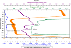
Figure F28. Sensor data, Hole M0076A.
Table T12. Sensor signal time log, Hole M0076A. Download table in .csv format.
Hole M0076B
The sensors started recording in Hole M0076B at 1739 h on 15 November 2015. Data for this hole are broken into three separate sections as a result of the need to recycle power to the RD2 drill that necessitated a restart of the CTD software each time (Figure F29). All the times and bit depths for relevant events are listed in Table T13.
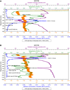
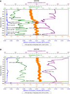
Figure F29. Sensor data, Hole M0076B.
Table T13. Sensor signal time log, Hole M0076B. Download table in .csv format.
The touchdown of the drill at 1926 h resulted in a small but significant jump in pH from 7.84 to 7.86, indicating that the sediments likely had a slightly higher pH than bottom seawater (Figure F29A, F29B). The CH4 background value was about 0.5 nM, and an increase in CH4 concentration began at about 2009 h, almost 30 min before drilling began, indicating that landing the drill likely displaced a shallow CH4 reservoir. The CH4 concentration reached a maximum value of 13.2 nM at 2100 h (1119 mm) about 13 min after drilling commenced for Core 1R. The CH4 peak reached background concentration at the start of Core 2R about 2 h and 20 min after it was started. This CH4 peak coincided with a significant drop in ORP, indicating that fluids more reducing than seawater were being flushed from the hole. A slight increase in temperature was also coincident with the CH4 and ORP excursions. After the initial disturbance centered at 2100 h, the next several hours of drilling were relatively uneventful with the exception of the event at 0446 h (Figure F29B), which included a negative ORP excursion, a temperature decrease, and a very small (1.3 nM) CH4 peak. This event took place well after the addition of a drill rod (0318–0339 h; 3934 mm) during the Core 3R run. Other than this small peak, CH4 concentrations remained around 0.5 nM.
From 1224 h on 16 November to 0639 h on 17 November, there was relatively little variation in sensor signals (Figure F29C). The most significant events were an ORP minimum at 2126 h and a small CH4 peak at 2128 h (1.7 nM) on November 16. The time difference between the ORP minimum and the CH4 peak is likely related to the time delay associated with diffusion across the METS membrane (see Water sampling and sensor package data in the Expedition 357 methods chapter [Früh-Green et al., 2017b]). The completion of Core 8R at 0133 h on November 17 corresponded with a coincident drop in ORP and a small CH4 maximum. The ORP excursion that reached a minimum at 0608 h while drilling Core 10R started after completion of Core 9R and well before Core 10R was started.
Cycling of the power on the RD2 drill caused a 31 min interruption in data after Core 10R started (Table T13), and it appears that a transient in methane concentration and ORP signal occurred during this period, as seen in the drop in methane concentration and ORP signal at the start of the third period of data (Figure F29D). At the end of the previous data set, methane concentration was 0.6 nM, whereas methane concentrations began at 5.9 nM (data taken from CTD file) at the start of the final data set. A drill rod was added while drilling Core 10R between 0631 and 0706 h at a depth of 15,239 mm. This new CTD file opened at 0713 h with the drill bit at 15,330 mm. After this excursion, CH4 remained about 0.6 nM for the rest of the deployment. The only other interesting feature during this period is the ORP excursion centered at 1237 h during attempts to drill an additional core. Coring ended with Core 10R at 0914 h (16,311 mm).
Borehole plugs
One successful attempt was made after RD2 drilling operations to install a borehole plug in Hole M0072B. For further details on borehole plugs, see Borehole plugs in the Expedition 357 methods chapter (Früh-Green et al., 2017b).
After tripping out the drill string in Hole M0072B, a three-unit borehole plug system was inserted into the open hole (Figure F30). The borehole plug consisted of a 2.17 m length of titanium tube with a ball-valve assembly at the upper end, an additional titanium rod in the center, and a packer element below. The entire length of the assembly was 5.12 m, with a stop ring on the upper titanium pipe set 1.02 m from the top of the assembly. Penetration reached 12.43 mbsf. The system penetrated to the target depth of 4.1 mbsf with the packer element set below 3.0 mbsf. The liftoff of the drill rig from the system stick up went well, and the top of the plug system likely sits about 1.02 m above the seafloor.
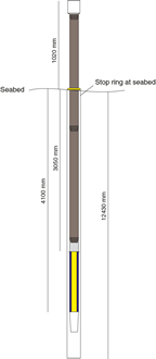
Figure F30. Borehole plug emplacement, Hole M0072B.
Because of difficult drilling conditions, coring equipment was left in two other central holes. In Hole M0069A, difficulty with handling operations resulted in the loss of the entire BHA and drill string in the hole. The entire string of eight drill rods plus the BHA totaled 16.8 m. This string was left behind in a 16.44 m hole, so it is possible that 0.44 m of pipe sticks out from the seafloor at this location (Figure F31). Similarly, difficult drilling conditions resulted in the loss of seven drill rods and a BHA in Hole M0076B. This 15 m length of equipment is likely beyond reach in the 16.3 m borehole (Figure F32).
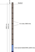
Figure F31. Equipment left behind in borehole, Hole M0069A.

Figure F32. Equipment left behind in borehole, Hole M0076B.
Physical properties
Site M0076
At Site M0076, two holes were cored with a total recovery of ≈12 m. The deeper hole (M0076B), which was cored to a total depth of 16.3 mbsf, had significantly better recovery (71%) than the shallower Hole M0076A (1.72 mbsf; ≈23% recovery). Physical properties measurements were acquired from all cores, including measurements on four samples from Hole M0076B.
Density and porosity
Gamma density (GD) for Hole M0076A varies between 1.43 and 2.52 g/cm3 and has a mean of 2.00 g/cm3 (Figure F33). Hole M0076B cores have gamma densities with a similar range but slightly higher values between 1.74 and 2.83 g/cm3 and a mean density of 2.34 g/cm3 (Figure F34). The overall mean density for this site is 2.34 g/cm3 (Table T14). This range is likely indicative of the fractured nature of the rock in this hole, with lower densities a function of poor core quality associated with more fragmented intervals. Density does not vary significantly with depth.
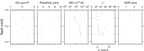
Figure F33. Physical properties, Hole M0076A.
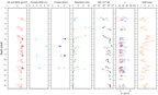
Figure F34. Physical properties, Hole M0076B.
Table T14. Physical properties, Sites M0076, M0069, and M0072. Download table in .csv format.
Four different serpentinite samples were taken from Hole M0076B for moisture and density (MAD) and triaxial P-wave velocity measurements (see below) at 5.96, 7.38, 9.19, and 11.60 mbsf (Figure F34; Table T15). These samples include two serpentinized harzburgites, one serpentinized dunite, and one serpentinized peridotite. Their average grain density is 2.60 ± 0.03 g/cm3. Their porosity varies more significantly between 3.1% and 8.9%. No Hole M0076A samples were analyzed.
Table T15. Grain density, porosity, and P-wave velocity for discrete samples, Sites M0076, M0069, and M0072. Download table in .csv format.
Bulk densities from MAD analyses are comparable to the corresponding gamma density measurement (Figure F34). Preferential sampling in more coherent intervals means that the MAD data set has overall higher mean densities than the whole-core data.
P-wave velocity
Sample 357-M0076B-4R-1, 80.0–82.0 cm, measured under wet conditions, has an x-direction velocity of 5.60 km/s (Figure F34, Table T15). The x-direction is horizontal in real space. The second horizontal direction, the y-direction, has a higher P-wave velocity (6.35 km/s). P-wave velocity measured along the z-direction (vertical) is 6.29 km/s. Mean P-wave velocity for this sample is 6.08 km/s. Sample 5R-1, 65.0–67.0 cm, also measured under wet conditions, has an x-direction velocity of 4.12 km/s. The y-direction for this sample has a higher P-wave velocity (4.63 km/s). P-wave velocity measured along the z-direction is 4.64 km/s. Mean P-wave velocity for this sample is 4.46 km/s. Sample 6R-1, 121.0–123.5 cm, was measured twice under dry conditions, resulting in x-direction velocities of 4.96 and 5.72 km/s, one y-direction velocity of 6.10 km/s, and vertical z-direction velocities of 6.46 and 6.05 km/s. The mean of all measurements is 5.86 km/s. Sample 8R-1, 44.5–47.0 cm, could only be measured in the x- (4.20 km/s) and z-directions (5.99 km/s) because the sample showed numerous fissures parallel to the y-direction. The mean P-wave velocity for this sample is 5.09 km/s.
Electrical resistivity
Electrical resistivity in Hole M0076A varies from 3.1 to 9.2 Ωm (Figure F33); the range in resistivity is greater in Hole M0076B (from 0.2 to 17.8 Ωm), and the mean is lower (2.8 Ωm) (Figure F34). Two major peaks in electrical resistivity occur in Hole M0076B at 3.7 and 5.2 mbsf. Both of these resistivity highs coincide with intervals of rubble (see Lithology, alteration, and structure). Data are more likely a function of poor core quality, rather than representative of the resistivity of the samples involved. Deeper in this hole, below 12.2 mbsf, cores have very low electrical resistivity, varying between 0.4 and 1.6 Ωm.
Magnetic susceptibility
In Hole M0076A, magnetic susceptibility (MS) is moderately high and ranges between 45 × 10–5 and 528 × 10–5 SI (Figure F33). In Hole M0076B, magnetic susceptibility is typically high with a mean value of 1283 × 10–5 SI and ranges from 22 × 10–5 to 5477 × 10–5 SI (Figure F34). Overall, magnetic susceptibility increases with depth. In both holes, magnetic susceptibility is anticorrelated with electrical resistivity.
Natural gamma radiation
Natural gamma radiation (NGR) measurements on Site M0076 cores are consistently very low, a reflection of the lithologies encountered (Figures F33, F34). There is no net change in NGR with depth, although there is clearly variability along the profile. In Hole M0076B, NGR increases overall to a maximum at ≈6.5 mbsf and decreases again with depth (Figure F34). Other maxima are noted at ≈5.1, 5.6, 7.1, 8.0, 11.1, and 12.0 mbsf. Because of the uncalibrated nature of the NGR counts per second, absolute values are not presented here.
Color reflectance
Color reflectance measurements were taken on all Site M0076 cores (Figures F33, F34; Table T14). Lightness (L*) in Hole M0076A varies from 24.45% to 58.26% with a mean value of 36.88%. a* and b* mean values are 0.75 and 5.64, respectively. a* values are relatively constant, ranging from –0.36 to 4.25, but b* values are highly scattered (between –0.71 and 13.69). L* in Hole M0076B varies between 19.37% and 58.85% with a mean value of 36.30%, which is comparable to that of the shallower Hole M0076A. a* is less variable than other color reflectance parameters, varying between –6.45 and 2.29 with a mean of –0.66. b* varies from –2.26 to 14.05 and has a mean of 2.17.
Site M0069
One hole was cored at Site M0069. Hole M0069A is the deepest hole (≈16.4 m) and the hole with the highest recovery (75%) across all sites drilled during Expedition 357.
Density and porosity
In Hole M0069A, gamma density ranges from 1.49 to 2.76 g/cm3 (Table T14; Figure F35), corresponding to the density of water-saturated sediments and altered mafic/ultramafic rocks, respectively. The mean gamma density is 2.29 g/cm3. A clear change in density occurs at 6.9 mbsf, coincident with the boundary between these two units. Above 6.9 mbsf, density varies between 1.65 and 2.00 g/cm3 and overall exhibits less scatter than is found deeper in the hole. Below 6.9 mbsf, gamma density varies between 1.49 and 2.75 g/cm3, with high variability observed over short distances. This variability is the effect of drilling-induced fractures, which are observed especially at the top of individual cores.
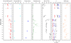
Figure F35. Physical properties, Hole M0069A.
Density and porosity were calculated for Site M0069 discrete samples (Figure F35; Table T15). Three sediment samples were taken at 0.49, 2.21, and 5.65 mbsf in the upper portion of Hole M0069A (above 6.9 mbsf). Their grain density is 2.65 ± 0.08 g/cm3, and their porosity is 56.1% ± 2.2%. There are no systematic changes in these parameters with depth. The spread in the three density parameters (grain, bulk, and dry) is significant compared to measurements on the rock minicores. This is to be expected because of the much larger sediment porosities. The metadolerite sample from 7.95 mbsf has a grain density of 2.87 g/cm3 and a porosity of 11.4%. The grain density and porosity of the talc-amphibole-chlorite schist sample (12.47 mbsf) are 2.95 g/cm3 and 6.8%, respectively, and those of the serpentinized harzburgite sample (15.57 mbsf) are 2.64 g/cm3 and 8.5%, respectively. The schist and metadolerite samples have higher bulk density than the equivalent gamma density measurement. These higher values are a function of preferential sampling of more coherent material for the discrete measurements.
P-wave velocity
Three discrete hard rock samples were obtained from Site M0069 cores (Figure F35; Table T15). The metadolerite sample (357-M0069A-5R-1, 107.0–109.0 cm) has an x-direction (horizontal) P-wave velocity of 5.81 km/s. The y-direction (horizontal) has a lower P-wave velocity (5.39 km/s). P-wave velocity measured along the z-direction (vertical) is 5.11 km/s. The mean P-wave velocity for metadolerite is 5.44 km/s. P-wave velocity of talc-amphibole-chlorite schist (Sample 8R-1, 114.5–117.0 cm) could only be reliably measured in the y-direction (horizontal): 4.75 km/s. The serpentinized harzburgite sample (10R-1, 85.0–87.0 cm) permitted reliable measurement in the y- and z-directions with P-wave velocities of 3.86 and 3.65 km/s, respectively, and an average of 3.76 km/s. This value is very low for serpentinized harzburgite, which can be tentatively explained by the multitude of healed hairline cracks in the cylindrical sample.
Electrical resistivity
Electrical resistivity in Hole M0069A is very low, ranging from 0.6 to 1.2 Ωm above 6.9 mbsf (Figure F35; Table T14), and principally reflects the resistivity of the seawater pore water. Resistivity is controlled by the porosity of these cores. This low electrical resistivity, in tandem with the low density, is indicative of water-saturated sediment in the upper part of this hole. Between 7.0 and 13.5 mbsf, resistivity increases with much greater scatter, varying between 0.3 and 23.3 Ωm. Below 13.5 mbsf, electrical resistivity decreases again to around 2 Ωm. This decrease is likely due to highly fractured, water-saturated core in which resistivity is porosity controlled.
Magnetic susceptibility
In Hole M0069A, magnetic susceptibility ranges from 1 × 10⁻⁵ to 8363 × 10–5 SI (mean = 1041 × 10–5) with a trend similar to that of gamma density (Table T14; Figure F35). Electrical resistivity in the sediment interval also seems to follow the trend of magnetic susceptibility. Between 7.0 and 13.5 mbsf, magnetic susceptibility first increases to 5268 × 10–5 SI (7.1 mbsf) and then decreases to a mean of 109 × 10–5 SI between 8.5 and 13.5 mbsf. The deepest part of Hole M0069A (below 13.5 mbsf) exhibits the highest magnetic susceptibility values, between 1952 × 10–5 and 8363 × 10–5 SI, indicating higher contents of magnetic minerals.
Natural gamma radiation
Similar to Site M0076, Site M0069 cores have consistently low NGR with no overall change in intensity with depth (Figure F35). Between ≈5 and 14 mbsf, values are slightly lower on average, and the underlying material and overlying sediments have slightly higher values. There is no clear distinction in this parameter between unconsolidated sediment and basement material, which is expected because the sediments are principally calcareous (see Lithology, alteration, and structure) and the heterogeneous lithologies of the basement have very low natural radioactivity.
Color reflectance
In Hole M0069A, L* varies between 19.50% and 77.43% with a mean value of 49.40% (Table T14; Figure F35). Mean values of a* and b* are 0.35 and 7.91, respectively. There are clear differences between shallow sediment cores (above 6.9 mbsf; above and including Core 5R) and deeper hard rock cores. For shallower cores, a* and b* are both positive, indicating chromaticity in the red and yellow parts of the spectrum, respectively. The deeper basement material is characterized by predominantly negative a* (green) and values of b* close to zero, indicating dominantly greenish gray colors. L* is significantly higher in sediment cores, indicating much lighter core material compared to the darker (lower L*) underlying cores. Scattering of the parameters is more pronounced in the deeper cores. These observations are consistent with the homogeneous sediment structure in the shallower cores and the highly heterogeneous mafic and ultramafic intervals in the deeper part of Hole M0069A.
Site M0072
Two holes were drilled at Site M0072, recovering a total of ≈13.8 m of material. Hole M0072B, the deeper (11.6 mbsf) of the two holes, had higher recovery (52%) than the shallower (2.2 mbsf) Hole M0072A, which had 39% recovery.
Density and porosity
In Hole M0072A, density varies between 1.51 and 2.63 g/cm3 with a mean of 2.01 g/cm3 (Figure F36). This large variation is a consequence of the highly fractured nature of the rocks in this hole. In Hole M0072B, gamma density ranges from 1.61 to 2.77 g/cm3 with a mean of 2.35 g/cm3 (Figure F37). In the uppermost 4 m of this hole, the mean density is 2.13 g/cm3. For the deeper cores, a slight net decrease in density is observed, with a mean value of 2.44 g/cm3. Larger density variations are observed at the tops of cores and are likely a function of drilling-induced fractures. A serpentinized harzburgite sampled from material recovered from Hole M0072B (11.02 mbsf) has a grain density of 2.58 g/cm3 and a porosity of 4.3% (Table T15).
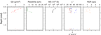
Figure F36. Physical properties, Hole M0072A.
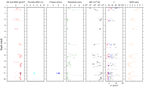
Figure F37. Physical properties, Hole M0072B.
P-wave velocity
One discrete serpentinized harzburgite sample (357-M0072B-8R-1, 31.0–33.0 cm) from Site M0072 was analyzed (Figure F37; Table T15). It has an x-direction (horizontal) P-wave velocity of 5.29 km/s. The second horizontal direction, the y-direction, has a higher P-wave velocity of 6.20 km/s. P-wave velocity measured along the z-direction (vertical) is 5.79 km/s. The mean P-wave velocity for the serpentinite is 5.76 km/s.
Electrical resistivity
Electrical resistivity ranges from 2.0 to 24.8 Ωm in Hole M0072A (mean = 5.4 Ωm) (Figure F36). In Hole M0072B, resistivity does not exhibit two distinct populations with depth as the gamma density does (Figure F37). In general, electrical resistivity is low to moderate (Table T14). In the first core, it reaches the highest values encountered in the hole (7.5 Ωm at ≈0.3 mbsf). Between 2.5 and 5.0 mbsf, resistivity is low with a mean value of 0.5 Ωm. Below 6.0 mbsf, fluctuating high and low electrical resistivity was observed, with values ranging from 0.3 to 6.9 Ωm and a mean of 1.6 Ωm.
Magnetic susceptibility
In Hole M0072A, magnetic susceptibility is low to moderate, from 31 × 10–5 to 360 × 10–5 SI, with a mean of 113 × 10–5 SI (Figure F36). In Hole M0072B, aside from the first core, magnetic susceptibility appears clearly anticorrelated with electrical resistivity (Figure F37). Overall, magnetic susceptibility varies between 6 × 10⁻⁵ and 5814 × 10–5 SI and is high, with the exception of the first core, with a mean value of 1632 × 10–5 SI.
Natural gamma radiation
At Site M0072, NGR is low, similar to the two other sites in the central area (Figures F36, F37; Table T14). The downhole profile observed in Hole M0072B suggests a very subtle net decrease in the intensity of NGR with depth.
Color reflectance
Color reflectance measurements were taken on the split surfaces of the archive halves of all Site M0072 cores. Hole M0072A cores have low L* variation between 31.03% and 52.62% with a mean value of 38.55% (Table T14; Figure F36). a* (mean = –0.87) and b* (mean = 0.53) are close to zero, clearly indicating a gray color, and relatively consistent with depth, ranging from –1.63 to –0.23 (a*) and from –0.51 to 1.75 (b*). In Hole M0072B, L* varies between 23.52% and 79.00%, and the mean value is 44.34% (Table T14; Figure F37). a* ranges from –5.44 to 4.01 (mean = –1.46), and b* ranges from –2.10 to 15.35 (mean = 1.77). It is mostly deeper cores that demonstrate these large variations in the color space dimensions. Above 2.5 mbsf, the scatter in L*, a*, and b* is lower than it is in the deeper part of the hole.
Summary
More than 30 m of core was recovered across the central sites during Expedition 357. Physical properties measurements were taken on all recovered material, including 11 samples utilized for MAD analyses and triaxial P-wave measurements. The central sites are characterized by moderate to high magnetic susceptibilities and excursions in resistivity that are far less common in the other areas studied during Expedition 357. These two parameters are typically anticorrelated, which is particularly evident at Sites M0076 and M0072 (Figures F34, F37). Any systematic relationship between magnetic susceptibility and resistivity is less well defined at Site M0069.
The sediment interval that caps Hole M0069A has distinct physical properties responses, as expected (Figure F33). There is a clear demarcation in all physical properties parameters at the sediment/rock interface at ≈6.9 mbsf. Three principal units in Hole M0069A are defined by physical properties parameters: the calcareous sediment cover (above ≈6.9 mbsf), an interval dominated by metadolerite (≈6.9–13.5 mbsf), and a unit of serpentinized harzburgite with dunitic intervals (≈13.5 mbsf and below) (see Lithology, alteration, and structure). Such units at the other central sites are less easy to define purely on the basis of the petrophysical measurements acquired.
A crossplot of density and porosity from the 11 MAD samples indicates some clear populations in the density-porosity space that can be attributed to lithology. The serpentinized lithologies (referred to as serpentinites in Figure F38) and calcareous sediments have lower densities than metadolerite and schist. The porosity of the sediments is very high compared to that of the hard rock samples.
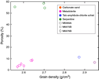
Figure F38. Grain density and porosity data from MAD analyses, Holes M0069A, M0072B, and M0076B.
Downhole logging
A 15 m interval of Hole M0076B was logged through-pipe utilizing the OAG tool (see Downhole logging in the Expedition 357 methods chapter [Früh-Green et al., 2017b]) over a period of 1 h. Because the drill pipe became irrevocably stuck, it was not possible to recover the drill string to the RD2, and therefore open-hole logging operations in this hole were not possible. However, deployment of the OAG tool through the stuck drill string allowed acquisition of a through-pipe total gamma ray measurement.
Operations
Downhole logging operations in Hole M0076B commenced at 1250 h local time on 17 November 2015. Challenging hole conditions resulted in the drill string becoming stuck, and the hole was terminated at 16.31 mbsf. Attempts to free the pipe ceased with a final bit depth for logging of 15.37 mbsf (Figure F39). Instead of open-hole logging operations, the OAG tool was deployed to acquire through-pipe total gamma ray data.
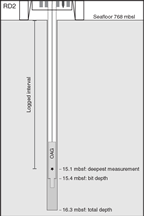
Figure F39. Geometry of logging from the RD2, Hole M0076B.
The OAG tool was retrieved from its magazine and connected to the winch cable with an overshot. The tool was then initialized, data acquisition for the winch depth encoder was started, and the tool was deployed via cable to the bottom of the drill string with the gamma measurement point reaching a maximum depth of 15.08 mbsf. An initial uplog was undertaken at a speed of ≈180 m/h. This uplog was followed by a repeat pass from the bottom of the drill string, after which the OAG tool was disengaged from the winch cable and returned to its magazine, ending logging operations at 1347 h.
Data processing and quality assessment
The seafloor is commonly used as the primary depth reference for downhole logging. However, as at all sites drilled during this expedition, very low gamma counts of the formations penetrated mean that confidently discerning the seafloor from the gamma logs is impossible. With the stable drilling platform (RD2) sitting on the seafloor, issues such as heave and tides commonly associated with logging operations in an offshore environment were not relevant, so the depth reference used for Hole M0076B was simply the depth encoder of the winch cable. The repeat pass of the OAG tool was used as the reference log, and the log from the initial pass was matched to this reference based on identification of common features to ensure consistency across the data sets.
The geometry of logging from a seabed drill is such that tool centralization is very effective, which is ideal for optimizing data quality.
With no open-hole measurements, it is difficult to comment on hole condition beyond any information reported by the drillers. The profile of a borehole affects the quality of any measurements acquired, whether they are taken in open hole or through-pipe. It is therefore difficult to comment on the impact of borehole condition on the data acquired and categorically say whether any changes in the gamma ray profile are due to the formation or the borehole diameter.
Undertaking two full passes of the borehole with the logging tool ensures that repeatability can be assessed, which provides a useful measure of data quality.
Logging stratigraphy
Extremely low levels of NGR through the formations penetrated by Hole M0076B means that dividing the profile into discrete logging units is not appropriate. The entire logged interval is therefore designated logging Unit 1.
Logging Unit 1 (0–15 mbsf) is characterized by very low gamma radiation ranging from 0 to 11 counts/s with a mean of 3.4 counts/s (Figure F40). There is no net change in gamma ray with depth; however, there are some notable features in the profile. The most significant peak is at 1.61 mbsf (11 counts/s). An interval of moderate gamma ray is evident from 3.3 to 6.1 mbsf, and two discrete zones of moderate gamma values center on 10.4 and 11.4 mbsf.
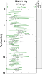
Figure F40. Total gamma ray downhole logging through pipe and core data, Hole M0076B.
Core-log correlations
NGR measurements were also acquired on the core material recovered from Hole M0076B (see Physical properties). These measurements are based on the same principle as that which the gamma sensor of the OAG tool is based (see Downhole logging and Physical properties, both in the Expedition 357 methods chapter [Früh-Green et al., 2017b]). However, a combination of the volume of material being measured, the lateral and vertical heterogeneity of the geology, and core recovery makes it complicated to reconcile the two data sets. That said, there do seem to be certain similarities in the downhole profiles of the core and logging gamma ray data (Figure F40), although depth matching the core data set to the downhole logs would likely improve this comparison.
Paleomagnetism
To achieve the main paleomagnetic objectives, magnetic susceptibility measurements (κ) and rudimentary analyses of natural remanent magnetization (NRM) were made on discrete specimens of known volume and mass (see Paleomagnetism in the Expedition 357 methods chapter [Früh-Green et al., 2017b]). Discrete samples were collected from Holes M0069A (three samples), M0072B (one sample), and M0076B (two samples). The magnetic susceptibility measured in these samples ranges from 0.00065 to 0.03706 SI units (Table T16). The lowest susceptibility values are found in a metadolerite and a talc-amphibole-chlorite schist from the shallower sections of Hole M0069A; the highest value corresponds to serpentinized harzburgite.
Table T16. Magnetic susceptibility and NRM inclinations of discrete samples, Sites M0069, M0072, and M0076. Download table in .csv format.
The NRM direction and intensity of these discrete samples were measured using the 2G-Enterprises SRM 755–4000 magnetometer. Results indicate that an alternating field (AF) of 5–20 mT is sufficient to remove a weak viscous remanent magnetization (VRM) for all samples from the central sites. There were two different responses to this sequential AF demagnetization (Figures F41, F42). Some samples lost 50% of their NRM intensity at alternating fields less than 40 to 50 mT (i.e., Samples 357-M0069A-10R-1, 82 cm, and 357-M0076B-8R-1, 87.5 cm, and 6R-1, 123.5 cm). Other samples (i.e., Samples 357-M0069A-8R-1, 112 cm, and 357-M0072B-8R-1, 28 cm) showed demagnetization typified by a paleomagnetic vector that is smoothly demagnetized up to the maximum alternating field demagnetization level of 100 mT, with a vector that does not trend toward the origin of the orthogonal projection. This magnetic behavior indicates that a characteristic remanent magnetization (ChRM) cannot be isolated, and it is therefore not possible to determine the inclination.

Figure F41. Typical AF progressive demagnetization for three samples, Hole M0069A.

Figure F42. Typical AF progressive demagnetization, Sites M0072 and M0076.
The paleomagnetic stability of the first category of samples was suitable for alternating field demagnetization, and it is possible to isolate a ChRM. Sections 357-M0069A-5R-1 and 10R-1 are associated with inclinations that approach the geocentric axial dipole (GAD) prediction of –49° for these sites (Table T16). The sample from Section 357-M0072B-8R-1 is characterized by an inclination value about 8.6° higher with respect to the GAD value. For Section 357-M0076B-6R-1, inclination is –49.1°, which is in agreement with the expected GAD value, and Section 8R-1 is characterized by an inclination of –40.8°, which is about 8.2° lower than the predicted value of the GAD model. Except for Section 357-M0069A-8R-1, where the inclination could not be determined, the other inclination values could plausibly be used for relative dating purposes.
References
Blackman, D.K., Karson, J.A., Kelley, D.S., Cann, J.R., Früh-Green, G.L., Gee, J.S., Hurst, S.D., John, B.E., Morgan, J., Nooner, S.L., Ross, D.K., Schroeder, T.J., and Williams, E.A., 2002. Geology of the Atlantis Massif (Mid-Atlantic Ridge, 30°N): implications for the evolution of an ultramafic oceanic core complex. Marine Geophysical Research, 23(5–6):443–469. http://dx.doi.org/10.1023/B:MARI.0000018232.14085.75
Früh-Green, G.L., Orcutt, B.N., Green, S.L., Cotterill, C., Morgan, S., Akizawa, N., Bayrakci, G., Behrmann, J.-H., Boschi, C., Brazelton, W.J., Cannat, M., Dunkel, K.G., Escartin, J., Harris, M., Herrero-Bervera, E., Hesse, K., John, B.E., Lang, S.Q., Lilley, M.D., Liu, H.-Q., Mayhew, L.E., McCaig, A.M., Menez, B., Morono, Y., Quéméneur, M., Rouméjon, S., Sandaruwan Ratnayake, A., Schrenk, M.O., Schwarzenbach, E.M., Twing, K.I., Weis, D., Whattam, S.A., Williams, M., and Zhao, R., 2017a. Eastern sites. In Früh-Green, G.L., Orcutt, B.N., Green, S.L., Cotterill, C., and the Expedition 357 Scientists, Atlantis Massif Serpentinization and Life. Proceedings of the International Ocean Discovery Program, 357: College Station, TX (International Ocean Discovery Program). http://dx.doi.org/10.14379/iodp.proc.357.103.2017
Früh-Green, G.L., Orcutt, B.N., Green, S.L., Cotterill, C., Morgan, S., Akizawa, N., Bayrakci, G., Behrmann, J.-H., Boschi, C., Brazelton, W.J., Cannat, M., Dunkel, K.G., Escartin, J., Harris, M., Herrero-Bervera, E., Hesse, K., John, B.E., Lang, S.Q., Lilley, M.D., Liu, H.-Q., Mayhew, L.E., McCaig, A.M., Menez, B., Morono, Y., Quéméneur, M., Rouméjon, S., Sandaruwan Ratnayake, A., Schrenk, M.O., Schwarzenbach, E.M., Twing, K.I., Weis, D., Whattam, S.A., Williams, M., and Zhao, R., 2017b. Expedition 357 methods. In Früh-Green, G.L., Orcutt, B.N., Green, S.L., Cotterill, C., and the Expedition 357 Scientists, Atlantis Massif Serpentinization and Life. Proceedings of the International Ocean Discovery Program, 357: College Station, TX (International Ocean Discovery Program). http://dx.doi.org/10.14379/iodp.proc.357.102.2017
Früh-Green, G.L., Orcutt, B.N., Green, S.L., Cotterill, C., Morgan, S., Akizawa, N., Bayrakci, G., Behrmann, J.-H., Boschi, C., Brazelton, W.J., Cannat, M., Dunkel, K.G., Escartin, J., Harris, M., Herrero-Bervera, E., Hesse, K., John, B.E., Lang, S.Q., Lilley, M.D., Liu, H.-Q., Mayhew, L.E., McCaig, A.M., Menez, B., Morono, Y., Quéméneur, M., Rouméjon, S., Sandaruwan Ratnayake, A., Schrenk, M.O., Schwarzenbach, E.M., Twing, K.I., Weis, D., Whattam, S.A., Williams, M., and Zhao, R., 2017c. Expedition 357 summary. In Früh-Green, G.L., Orcutt, B.N., Green, S.L., Cotterill, C., and the Expedition 357 Scientists, Atlantis Massif Serpentinization and Life. Proceedings of the International Ocean Discovery Program, 357: College Station, TX (International Ocean Discovery Program). http://dx.doi.org/10.14379/iodp.proc.357.101.2017
McDonough, W.F., and Sun, S.-S., 1995. The composition of the Earth. Chemical Geology, 120(3–4):223–253.
http://dx.doi.org/10.1016/0009-2541(94)00140-4
Sun, S.-S., and McDonough, W.F., 1989. Chemical and isotopic systematics of oceanic basalts: implications for mantle composition and processes. In Saunders, A.D., and Norry, M.J. (Eds.), Magmatism in the Ocean Basins. Geological Society Special Publication, 42:313–345.
http://dx.doi.org/10.1144/GSL.SP.1989.042.01.19
1 Früh-Green, G.L., Orcutt, B.N., Green, S.L., Cotterill, C., Morgan, S., Akizawa, N., Bayrakci, G., Behrmann, J.-H., Boschi, C., Brazelton, W.J., Cannat, M., Dunkel, K.G., Escartin, J., Harris, M., Herrero-Bervera, E., Hesse, K., John, B.E., Lang, S.Q., Lilley, M.D., Liu, H.-Q., Mayhew, L.E., McCaig, A.M., Menez, B., Morono, Y., Quéméneur, M., Rouméjon, S., Sandaruwan Ratnayake, A., Schrenk, M.O., Schwarzenbach, E.M., Twing, K.I., Weis, D., Whattam, S.A., Williams, M., and Zhao, R., 2017. Central sites. In Früh-Green, G.L., Orcutt, B.N., Green, S.L., Cotterill, C., and the Expedition 357 Scientists, Atlantis Massif Serpentinization and Life. Proceedings of the International Ocean Discovery Program, 357: College Station, TX (International Ocean Discovery Program). http://dx.doi.org/10.14379/iodp.proc.357.104.2017
- F1. DSL120 sonar imagery and 50 m resolution multibeam bathymetry, Sites M0069, M0072 and M0076.
- F2. Location of Holes M0072A, M0072B, M0076A, M0076B, and M0069A.
- F3. Lithologic summary for central holes.
- F4. Aphyric vesicle-poor basalt. Coarse clinopyroxene partially includes tabular plagioclase grains.
- F5. Alteration, Hole M0076B.
- F6. Intensely oxidized and serpentinized dunite pieces, carbonate and serpentine veined harzburgite, and subvertical veins cutting serpentinized peridotite.
- F7. Metasomatic alteration of a possibly originally magmatic vein that subvertically crosscuts serpentinized harzburgite.
- F8. Amphibole- and talc-bearing shear zone.
- F9. High-intensity cataclastic deformation in dolerite, steeply dipping composite amphibole and chlorite (± talc) vein cutting serpentinized porphyroclastic harzburgite, and moderately dipping carbonate vein with oxidation cutting pyroxene-poor serpentinized dunite.
- F10. Mineral phases identified by bulk powder XRD analysis, Holes M0076B, M0072B, and M0069A.
- F11. Alteration, Hole M0072B.
- F12. Complex shear zone showing a transition from static alteration to strain localization in alternating talc-, amphibole-, and chlorite-rich shear zones.
- F13. Magmatic intrusion into a fully serpentinized harzburgite. Late metasomatic alteration at the boundary of the mafic/ultramafic rocks produced a white and green talc-amphibole-chlorite assemblage that crosscuts the previous texture.
- F14. Serpentinite partially metasomatized to chlorite-amphibole-talc.
- F15. Fine-grained breccia in contact with a schistose talc-amphibole shear zone hosting brittlely deformed clasts of metadolerite.
- F16. Serpentinized peridotite.
- F17. Serpentinized harzburgite with chromian spinel grain.
- F18. Alteration, Hole M0069A.
- F19. Amphibole-chlorite zone with large metadolerite clast, serpentinized dunite presenting a mesh to ribbon texture underlined by preferentially oriented magnetite concentrations along microfractures, and serpentinized dunite crosscut by multiple carbonate veins bordered by significant oxidation.
- F20. Alteration of pale, irregular, patchy alteration observed in metadolerites. Yellow-brown patches are chlorite rich and cut by epidote veins.
- F21. Deformation and dolerite intrusion, Hole M0069A.
- F22. Cataclasis of a chlorite-rich interval and no consistent foliation.
- F23. Chondrite-normalized REE plot, Holes M0069A and M0072B.
- F24. Primitive mantle–normalized extended trace element plot, Sites M0069, M0072, and M0076.
- F25. Sensor data, Hole M0069A.
- F26. Sensor data, Hole M0072A.
- F27. Sensor data, Hole M0072B.
- F28. Sensor data, Hole M0076A.
- F29. Sensor data, Hole M0076B.
- F30. Borehole plug emplacement, Hole M0072B.
- F31. Equipment left behind in borehole, Hole M0069A.
- F32. Equipment left behind in borehole, Hole M0076B.
- F33. Physical properties, Hole M0076A.
- F34. Physical properties, Hole M0076B.
- F35. Physical properties, Hole M0069A.
- F36. Physical properties, Hole M0072A.
- F37. Physical properties, Hole M0072B.
- F38. Grain density and porosity data from MAD analyses, Holes M0069A, M0072B, and M0076B.
- F39. Geometry of logging from the RD2, Hole M0076B.
- F40. Total gamma ray downhole logging through pipe and core data, Hole M0076B.
- F41. Typical AF progressive demagnetization for three samples, Hole M0069A.
- F42. Typical AF progressive demagnetization, Sites M0072 and M0076.
- T1. Central sites hole summary.
- T2. X-ray diffraction results, Holes M0069A, M0072B, and M0076B.
- T3. Whole-round cores collected for microbiological analysis, Sites M0069, M0072, and M0076.
- T4. Core liner fluid samples for microbiological analyses, Sites M0069, M0072, and M0076.
- T5. Microbial cell abundance counted on flame-sterilized interior piece of rock samples, Sites M0069 and M0072.
- T6. Water samples collected from sensor package Niskin bottles for microbiological analysis, Sites M0069, M0072, and M0076.
- T7. Water samples collected from CTD Rosette Niskin bottles for microbiological analyses, Sites M0069 and M0072.
- T8. Microbial cell abundance counted on water samples, Site M0069.
- T9. Sensor signal time log, Hole M0069A.
- T10. Sensor signal time log, Hole M0072A.
- T11. Sensor signal time log, Hole M0072B.
- T12. Sensor signal time log, Hole M0076A.
- T13. Sensor signal time log, Hole M0076B.
- T14. Physical properties, Sites M0076, M0069, and M0072.
- T15. Grain density, porosity, and P-wave velocity for discrete samples, Sites M0076, M0069, and M0072.
- T16. Magnetic susceptibility and NRM inclinations of discrete samples, Sites M0069, M0072, and M0076.
G.L. Früh-Green, B.N. Orcutt, S.L. Green, C. Cotterill, S. Morgan, N. Akizawa, G. Bayrakci, J.-H. Behrmann, C. Boschi, W.J. Brazelton, M. Cannat, K.G. Dunkel, J. Escartin, M. Harris, E. Herrero-Bervera, K. Hesse, B.E. John, S.Q. Lang, M.D. Lilley, H.-Q. Liu, L.E. Mayhew, A.M. McCaig, B. Menez, Y. Morono, M. Quéméneur, S. Rouméjon, A. Sandaruwan Ratnayake, M.O. Schrenk, E.M. Schwarzenbach, K.I. Twing, D. Weis, S.A. Whattam, M. Williams, and R. Zhao2
Keywords: International Ocean Discovery Program, IODP, RRS James Cook, Expedition 357, Site M0069, Site M0072, Site M0076, seabed drills, RD2, MeBo, Atlantis Massif, Atlantis Fracture Zone, Mid-Atlantic Ridge, Lost City hydrothermal field, serpentinization, detachment faulting, oceanic core complex, hydrogen, methane, deep biosphere, carbon cycling, carbon sequestration, contamination tracer testing
MS 357-104: Published 4 February 2017
Operations
During Expedition 357, cores were recovered from three sites in the central area of Atlantis Massif: Sites M0069, M0072, and M0076 (Figure F1; Table T1). Newly acquired multibeam data, combined with preexisting data sets, were evaluated prior to each site to guide the drill teams with regard to anticipated seabed conditions and slope.
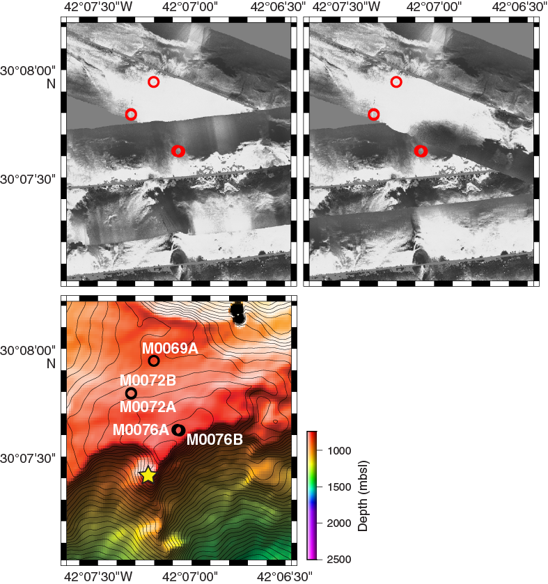
Figure F1. DSL120 sonar imagery and 50 m resolution multibeam bathymetry, Sites M0069, M0072 and M0076.
Table T1. Central sites hole summary. Download table in .csv format.
Site M0069
Cores were recovered from one hole at proposal Site M0069 (proposed Site AM-06), with an average site recovery of 74.76%. The water depth was 850.90 m with no tidal range. The total time spent on station was 2.04 days.
Hole M0069A
The RSS James Cook arrived on station at Site M0069 and settled into dynamic positioning (DP) mode at 0915 h on 6 November 2015. The conductivity, temperature, and depth (CTD) sensor package was deployed at 0922 h. At 1006 h, the CTD was 1.7 m off the bottom, and the first three Niskin bottles were fired. Two further Niskin bottles were fired on the way up, with a final one near the surface (see Table T5 in the Expedition 357 summary chapter [Früh-Green et al., 2017c]). The CTD was recovered on deck at 1038 h on 6 November.
At 1201 h, Meeresboden-Bohrgerät 70 (MeBo) drill deployment began. A full systems check was performed at ≈100 m water depth at 1304 h, but at 1337 h we found a hydraulic leak on the umbilical winch. After investigation, the deployment was continued, but further leaking from the umbilical winch led to the decision to abort the dive at 1425 h. The MeBo was recovered to the deck and was secure by 1530 h. The British Geological Survey RockDrill2 (RD2) was prepared for deployment because the predicted weather would put the swell outside the operational range for relaunching the MeBo.
At 2002 h, the RD2 was deployed, stopping for a full systems check at ≈300 m water depth. At 2111 h, the bridge requested the RD2 be stopped while they checked out a problem with GPS2. The RD2 held ≈40 m off seafloor for 30 min before continuing to the seafloor. Coring operations commenced at 2204 h. Coring continued steadily for 10 core runs; runs were completed at 2218 h on 6 November; 0057, 0510, 0726, 1113, 1413, 1705, 1921, and 2205 h on 7 November; and 0249 h on 8 November. Core Run 11 commenced at 0448 h. However, a technical problem with the gate valve resulted in the reduction of flushing down the borehole. The drill rods became stuck, and the drill string, including core Barrel 11, was lost in the hole after attempts to free the rods were unsuccessful. The RD2 was recovered on deck by 0800 h on 8 November.
During recovery, the Niskin bottles on the drill were triggered but did not close, and thus they remained open at the top until about 40 min after the drill was recovered. It was surmised that, because the bottoms of the bottles were sealed, the trip through the water column would result in minimal mixing and loss of bottom water. Indeed, later analysis of these samples showed significantly elevated H2 and CH4 concentrations. Additionally, as soon as the drill was recovered, a ship’s CTD cast was conducted over the drill site to retrieve postdrilling fluid samples for geochemistry and microbiological analyses. The CTD was deployed at 0853 h. At 0933 h, the CTD was 2.1 m off the bottom, and four Niskin bottles were fired. No other bottles were fired mid–water column or near surface, and the CTD was recovered on deck at 0955 h. The vessel departed station immediately on recovery of the CTD on deck.
In summary, 10 coring attempts were made in Hole M0069A to a maximum depth of 16.44 m with 74.76% recovery.
Site M0072
Cores were recovered from two holes at Site M0072 (proposed Site AM-01A), with an average site recovery of 53.29%. The water depth was 820.30 m with no tidal range. Two additional CTD casts were linked to this site (Holes M0072X and M0072Z) (see Table T5 in the Expedition 357 summary chapter [Früh-Green et al., 2017c]). The first was conducted over the Atlantis Fracture Zone at a water depth of ≈4244 m. The second was conducted in close proximity to Lost City at a water depth of ≈850 m. The total time spent on station was 2.16 days.
Hole M0072A
At 0532 h on 10 November 2015, the vessel began the transit to Site M0072 from Site M0071. By 0610 h, the vessel was on DP mode and the ship’s CTD was prepared for deployment. By 0723 h, the CTD cast was complete, having reached ≈1.8 m off the seafloor. Three Niskin bottles were fired near the seafloor, two mid–water column, and one near the surface (see Table T5 in the Expedition 357 summary chapter [Früh-Green et al., 2017c]).
By 0736 h, the ship was settled into DP mode, centered over the port-side deployment position for the RD2, and the drill was prepared for launch. The RD2 was deployed at 1010 h. At 1045 h, following mid–water column checks, it was discovered that the drill-mounted CTD sensor package had not been started. However, due to the ability to start the sensor remotely, the deployment continued, and at 1114 h the drill was positioned on the seafloor. Coring operations commenced at 1129 h, with the first core run completed by 1252 h. The second core run commenced at 1418 h. However, this run was aborted at 1438 h after consultation with the Co-Chief Scientists when it was discovered that a borehole plug had not been loaded onto the drill. The RD2 was recovered to deck by 1535 h. The two core barrels were unloaded, and the drill was readied for redeployment.
In summary, two coring attempts were made in Hole M0072A to a maximum depth of 2.23 m with 39.10% recovery.
Hole M0072B
At 1642 h on 10 November 2015, the RD2 was deployed in Hole M0072B. The drill was on the seafloor at 1708 h, and coring commenced at 1717 h. Hole M0072A was visible ≈1 m away under the skid of the RD2. The first three core runs were completed at 1815, 2053, and 2319 h. On recovery, however, the third barrel stuck in the bottom-hole assembly (BHA) and remained stuck after attempts to remove it by flushing and rotating the drill rods. The rod and BHA were tripped with the barrel still inside, and a new BHA was deployed at 0229 h on 11 November. After discussion, it was decided to ream back down to the depth reached by Run 3 (5.10 m) and then open-hole past the problem area (believed to be caused by talc), and coring recommenced at 6 m. During this process, a sharp increase in torque was observed at the depth where the third barrel had become stuck.
Coring continued throughout 11 November with high torque observed again at 8.93 m, resulting in a short core run of only 1.28 m. The barrel of core Run 7 became stuck at 8.98 m but was recovered after flushing. At 0411 h on 12 November, it was noted that the umbilical had become twisted, possibly due to the influence of an increasing sea swell, causing disruption to the controls of the hydraulic systems and the onboard cameras. It was requested that the vessel move under DP, spinning about the drill position in an attempt to untwist the umbilical. It was initially believed that this had been successful, and the RD2 maintained position for 30 min to ensure communications were stable. However, communications were again lost, and the decision was made to recover the RD2 at 0535 h. It was decided not to attempt logging the hole with unstable communications to the subsea drill controller, but the Niskin bottles were fired at 0740 h and the packer was installed by 0805 h. By 0900 h, the RD2 was on deck and secure. The umbilical was damaged and needed retermination, requiring at least 12 h of work.
At 0830 h the Master of the Vessel decided that the sea state was becoming excessive for deployment of either drill, so at 0900 h the vessel departed the site to continue a multibeam survey across Sites M0070 and M0074.
In summary, eight coring attempts were made in Hole M0072B to a maximum depth of 12.43 m with 52.22% recovery.
Site M0076
Cores were recovered from two holes at Site M0076 (proposed Site AM-11A), with an average site recovery of 66.44%. The water depth was 768.00 m with no tidal range. The total time spent on station was 2.37 days.
Hole M0076A
The vessel arrived at Site M0076 at 1020 h on 15 November 2015 and settled into DP mode. RD2 predive checks were still ongoing at the time of arrival, and deployment was delayed until 1339 h. Coring operations began at 1456 h with rapid penetration to 1.72 mbsf (end of core Run 1) by 1523 h. A hydraulic leak on the headshift terminated the hole early, and the RD2 was recovered on deck by 1606 h. No Niskin bottles were fired under instruction from the Co-Chief Scientist on shift.
The MeBo was still being repaired following damage to the base plate and leg on a previous dive, so the RD2 was rapidly turned around and redeployed in Hole M0076B.
In summary, one coring attempt was made in Hole M0076A to a maximum depth of 1.72 m with 23.26% recovery.
Hole M0076B
The RD2 was redeployed at Site M0076 at 1731 h on 15 November 2015. After initially landing on the seafloor at 1812 h, the drill had to be repositioned because of a high slope angle caused by landing unevenly on cobbles/boulders. The RD2 finally settled on the seafloor at 2012 h after three attempts to reposition both the drill and the umbilical. Coring operations commenced at 2040 h. Coring continued well until the end of core Run 2 (0005 h on 16 November), when high flush had to be run until 0133 h to free the stuck core barrel. A further eight core runs were recovered at 0615, 0933, 1336, 1706, and 2158 h on 16 November and 0132, 0429, and 0914 h on 17 November. At 14.75 m penetration, high backpressure on the flush pump was noted due to a “sticky” section. At the start of core Run 11 (16.31 m), there was difficulty reaming back to the base of the hole. The rods became stuck due to failure of the gate valve, resulting in no flush flow into the borehole. There was difficulty removing the overshot spear point from the overshot, which was ultimately achieved using the fishing tool, which is slightly shorter in length.
Prior to attempting to free the drill rods, two optical-acoustic-gamma (OAG) logging passes were completed through the pipe. The tool was deployed at 1314 h, and logging operations were completed by 1347 h. Various attempts were then made to free the drill rods, enabling the last rod to be unscrewed and recovered. An attempt was then made to connect the borehole plug to the drill rods still in the borehole, but it could not be connected. In attempting connection, the “J” connection at the top of the plug parted, resulting in the plug being unconnected both top and bottom. It was clamped in the breakout jaws but was lost during recovery of the drill. The RD2 was recovered on deck by 1656 h on 17 November.
During coring, repairs on the MeBo drill were made to port and starboard leg positions, a missing base plate, and the leg connection point. Some areas were cut away to allow for welding of new plates to strengthen the frame. On recovery, the RD2 crew required 12–14 h of maintenance to get the drill operational again. As both drills were unavailable for deployment, we decided to continue with the multibeam survey, imaging the conjugate margin of the Atlantis Massif complex. The vessel departed Site M0076 at 1900 h on 17 November.
In summary, 10 coring attempts were made in Hole M0076B to a maximum depth of 16.31 m with 71.79% recovery.
Lithology, alteration, and structure
Three sites were drilled in the central region of Atlantis Massif: from east to west, Sites M0076, M0069, and M0072 (Figure F2). These sites are the closest to the Lost City hydrothermal field and have highly heterogeneous lithologies, types of alteration, and extents of deformation. Intact lithologic contacts and alteration and deformation relationships (in addition to paleomagnetic results; see Paleomagnetism) suggest that coring at these central sites recovered in situ sequences of the shallow mantle and detachment fault zone at the top of Atlantis Massif (see VCDs in Core descriptions).

Figure F2. Location of Holes M0072A, M0072B, M0076A, M0076B, and M0069A.
Two holes were drilled at Site M0076: Hole M0076A is shallow (0.4 m of core), and Hole M0076B extends to 16.31 mbsf and recovered 11.71 m of core (Figure F3). Hole M0076B consists mostly of long intervals of coherent core dominated by serpentinized harzburgite and dunite with veins or intervals of partially to highly altered gabbroic material and moderately foliated talc-amphibole-chlorite schist, some of which contain clasts of metagabbro. The bottom of the hole (Cores 9R and 10R) also contains several carbonate veins. Core recovery in Hole M0076B was high, with an overall average recovery of 71% and recovery better than 88% in Cores 4R, 5R, 7R, and 8R.
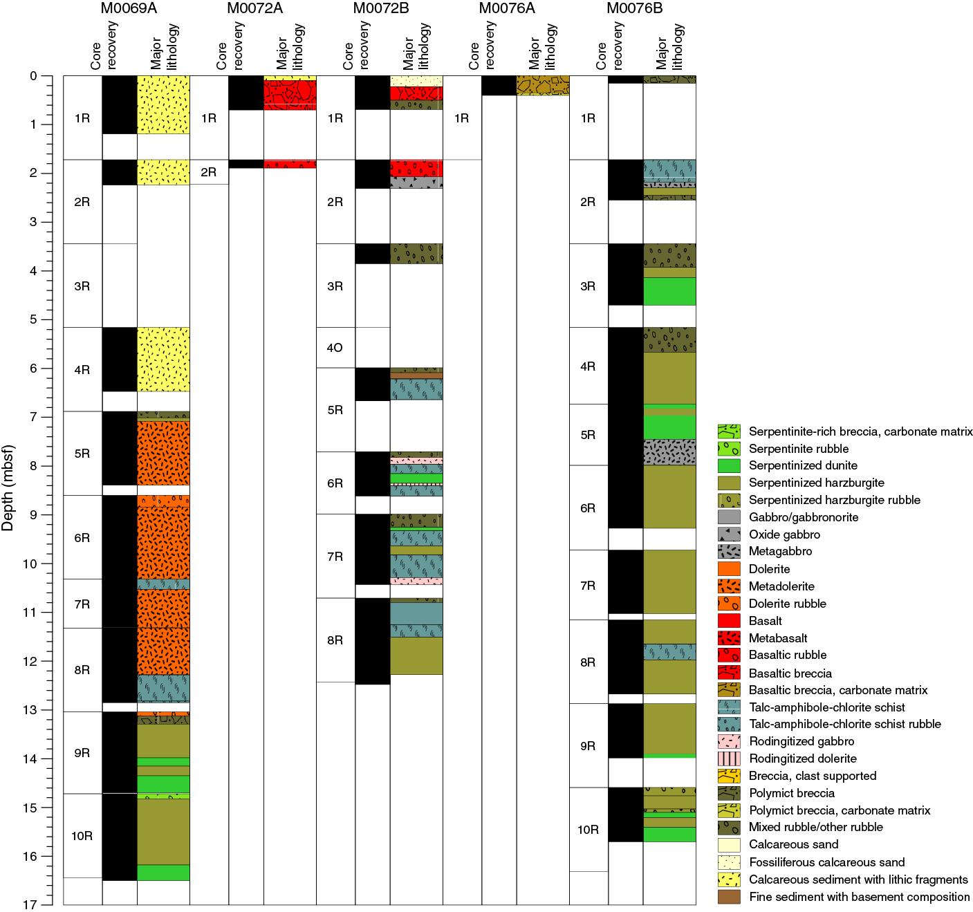
Figure F3. Lithologic summary for central holes.
The very top of both holes at Site M0076 is composed of calcareous sediment with basalt and some serpentinite fragments (Core 357-M0076B-1R). The very shallow Hole M0076A contains only this sedimentary material and a 5 cm thick interval of green mud with basalt and dolerite gravel.
Below the uppermost sediment interval in Hole M0076B, a principally coherent sequence is dominated by oxidized serpentinized harzburgite. The upper contact of this zone consists of talc-amphibole-chlorite schists that enclose small sections of metagabbro and oxidized serpentinized harzburgite. This zone transitions into coherent intervals of metagabbro and oxidized serpentinized harzburgite (bastite after orthopyroxene with grain sizes up to 10 mm, typically at a modal abundance of 10%–15%; Section 2R-1, Unit 3). Sections of mixed rubble (including fragments of serpentinized harzburgite, serpentinized dunite, metagabbro, and talc-amphibole-chlorite schist) with intervals of coherent serpentinites (Sections 3R-1 and 4R-1, Unit 1) overlie continuous sections of veined and serpentinized harzburgite alternating with serpentinized dunite (Section 4R-1, Unit 2, and below).
Hole M0072A is shallow (cored to 2.2 mbsf; recovered 0.87 m of core). Hole M0072B penetrated to 12.43 mbsf and recovered 6.5 m of core (Figure F3). Both holes have a shallow structural interval of sediment and rubble and two deeper intervals attributed to fault zones. Hole M0072B has long intervals of coherent core with three dominant lithologies: talc-amphibole-chlorite–bearing schist, serpentinized harzburgite with variably sheared veins of talc-amphibole material, and metagabbro and metadolerite, locally with reddish alteration. This style of localized red alteration was interpreted as rodingitization based on macroscopic observations, but the interpretation was not confirmed by thin sections.
Hole M0072A and the upper sections of Hole M0072B consist of surficial features including carbonate sands (with centimeter-scale subrounded basaltic lithic fragments), sedimentary basaltic breccias, and basaltic rubble (with rare oxide gabbro fragments observed in Hole M0072B). The sedimentary matrix in both holes contains foraminifers.
Four types of alteration were observed in Hole M0072B: serpentinization, talc-amphibole-chlorite metasomatism, oxidation, and rodingitization. Talc-amphibole-chlorite metasomatism is the most common alteration type and is present throughout. Serpentinization is the second most abundant alteration type and decreases in abundance below 8 mbsf. A complex fault zone was recovered below Core 5R. This zone shows alternating schistose, highly foliated regions of high strain hosting intervals of variably serpentinized peridotite with magmatic impregnations, and alteration to talc, tremolite, and chlorite. Several intervals of 5–15 cm thick rodingitized dolerite occur in this hole, with a strong mylonitic fabric observed locally (interval 6R-1, 18–24 cm).
Site M0069 consists of a single hole (Figure F3). Ten cores were drilled from Hole M0069A (one with no recovery), which penetrated 16.44 mbsf and recovered 12.29 m of core, constituting the overall highest percentage core recovery (74.76%) at any site. The upper four cores of the hole (1R–4R) recovered unconsolidated foraminiferal ooze and sands. The underlying cores (5R–10R) recovered mostly coherent hard rock with two dominant lithologies and distributions: amphibole-chlorite schist with intrusions and clasts of metadolerite in the upper part (Core 5R to Section 9R-1, 26 cm) and serpentinized and variably oxidized dunite within intervals of serpentinized harzburgite from Section 9R-1, 26 cm, to the bottom of the hole.
The mafic part of the hole comprises several intervals of strongly deformed schist, with a subhorizontal to moderately dipping foliation in the most deformed intervals. The lower contact of the mafic interval with serpentinized dunites is preserved and corresponds to a highly deformed interval with strong foliation and a pronounced reduction in grain sizes in the schist (interval 9R-1, 19–26 cm). This highly deformed interval may include intervals of gouge. The extent of deformation in the underlying serpentinized dunite and harzburgite is not clear from macroscopic observations. The lowermost 10 m of Hole M0069A shows three distinct structural units hosting several shear zones bounding intervals of dolerite and serpentinized dunite.
Site M0076
Rock types and igneous petrology
The predominant igneous rock type at Site M0076 is serpentinized porphyroclastic harzburgite with lesser mafic intervals (Figure F3). The upper sections of both holes are sedimentary basaltic breccias, with stratigraphy better preserved in Hole M0076A (including the overlying fossiliferous carbonate sediment; Section 357-M0076B-1R-1 contains mostly rubble). Below this uppermost interval of sediment, a principally coherent sequence of basement rocks is dominated by oxidized serpentinized harzburgite. The upper contact of this zone consists of talc-amphibole schists that enclose small sections of metagabbro and oxidized serpentinized harzburgite. In Section 357-M0076B-2R-1, Unit 3, a transition into coherent intervals of metagabbro and oxidized serpentinized harzburgite with bastite replacing orthopyroxene (grain size up to 10 mm), typically has a modal abundance of 10%–15%. Following sections of mixed rubble (including fragments of serpentinized harzburgite, serpentinized dunite, metagabbro, and talc-amphibole schists) with intervals of coherent serpentinites (Sections 3R-1 and 4R-1, Unit 1), Cores 5R and 6R are continuous sections of veined and altered alternating serpentinized harzburgites and serpentinized dunites (from Unit 2 downhole). The igneous petrology of Holes M0076A and M0076B is summarized on a core-by-core basis below (see VCDs in Core descriptions).
Hole M0076A
Hole M0076A consists of one core section with two lithologic units. Unit 1 comprises clasts of basalt, dolerite, and rare serpentinite set in a brown foraminifer-rich carbonate matrix. Clasts are poorly to moderately sorted. Unit 2 is mixed, unsorted breccia with subrounded clasts of basalt and dolerite as large as 2 cm. Basalts are slightly altered (≈30%), but primary olivine (5%), clinopyroxene (35%), and plagioclase (60%) remain (interval 1R-1, 28–31 cm). Plagioclase and clinopyroxene are fine to medium grained (maximum = 3 mm; average = 1.5 mm), and olivines are fine grained (maximum = 1 mm; average = 0.5 mm). Basalts are subophitic with subhedral tabular plagioclase crystals partially included in clinopyroxene. A sparsely vesicular (≈7%) aphyric subophitic basalt was observed under the microscope (Sample 1R-1, 28–31 cm) (Figure F4). Primary minerals include plagioclase (60%–65%), clinopyroxene (30%–35%), and olivine (3%), all of which are fine grained (≈1 mm). Approximately 20% of the primary assemblage has been altered to secondary hydrated minerals. Tabular plagioclase is euhedral to subhedral and partially enclosed by clinopyroxene.
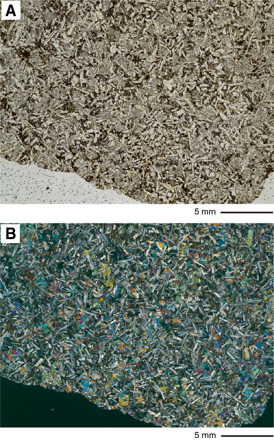
Figure F4. Aphyric vesicle-poor basalt. Coarse clinopyroxene partially includes tabular plagioclase grains.
Hole M0076B
Core 357-M0076B-1R consists of mafic rock–dominated carbonate breccia (Figure F5). Clasts comprise metagabbro, basalt, and one fragment of lithified breccia. The metagabbro includes dark cores (possibly olivine) surrounded by an unidentified white mineral (10% modal abundance), plagioclase (45% modal abundance), and clinopyroxene (45% modal abundance). The basalt contains 3%–4% vesicles (up to 1 mm) and is slightly oxidized along the edge. The fragment of carbonate breccia has a foraminifer-rich matrix and includes clasts of serpentinized harzburgite (bastites up to 5 mm × 10 mm; 20% modal abundance) and basalt in addition to talc schist clasts.
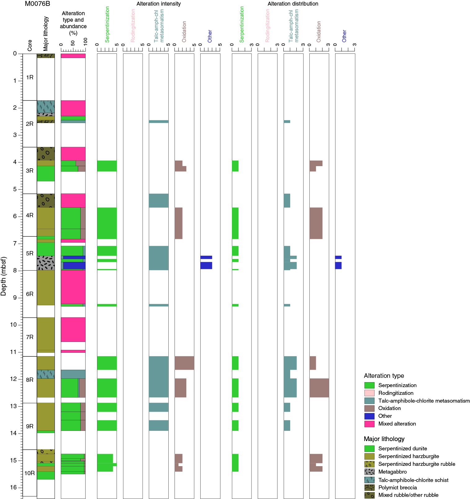
Figure F5. Alteration, Hole M0076B.
Section 2R-1 comprises four units. Unit 1 (0–46 cm) consists of talc-amphibole schist that contains fragments of gabbros and intervals defined by oxidized serpentinized harzburgite (at 19–25 and 44–46 cm). Unit 2 comprises metagabbro, and Unit 3 is oxidized serpentinized porphyroclastic harzburgite (15% modal abundance of relict pyroxene porphyroclasts, approximately 10 mm in diameter). The underlying unit is an interval of polymict breccia dominated by talc and serpentine clasts.
Core 3R contains mixed rubble (Unit 1), serpentinized harzburgite (Unit 2), and serpentinized dunite (Unit 3). The mixed rubble includes fragments of oxidized serpentinite, talc-amphibole schist, and coarse-grained metagabbro. The serpentinized dunite of Unit 3 is highly oxidized, preserves a well-developed mesh texture, and contains magnetite veins locally.
Core 4R is divided into three sections. Section 4R-1 contains two units. Unit 1 is composed of rubble of talc-amphibole-chlorite schist, locally oxidized serpentinite, and metagabbro. Unit 2 comprises oxidized serpentinized harzburgite (≈15% of 6–10 mm bastites) with infrequent magnetite veins. Sections 4R-2 and 4R-CC both contain slightly deformed oxidized serpentinized harzburgite that exhibits mesh texture. Four units are distinguished in Section 5R-1. Units 1 and 3 (below the microbiology sample at 0–36 cm) are highly serpentinized dunites with no evidence of primary mineral relics. A mesh texture is developed in the dunite but is highly sheared. The dunite is highly oxidized, particularly within the zones of mesh texture. These zones are separated by an interval of serpentinized harzburgite (Unit 3). Unit 4 (72–125 cm) comprises a metagabbro intrusion with intervals of serpentinized porphyroclastic harzburgite at 86–92, 101–114, and 121–125 cm. Section 5R-CC consists of fragments of serpentinized porphyroclastic harzburgite (approximately 20% bastites up to 7 mm) similar to that of Section 5R-1, Unit 2, described above (see VCDs in Core descriptions).
Core 6R contains serpentinized harzburgite infiltrated by melt intrusions. Bastites in the serpentinized harzburgite are 3–5 mm in diameter with an estimated modal abundance of 5%–10%.
Section 7R-1 also consists of serpentinized porphyroclastic harzburgite impregnated by several melt intrusions. Throughout most of the unit, bastites represent 5%–10% modally and are typically 1–6 mm in diameter. Melt intrusions were observed at 20 and 40 cm. Section 7R-CC contains clasts of oxidized serpentinized porphyroclastic serpentinites (bastites are 1–4 mm in diameter).
Section 8R-1 comprises serpentinized harzburgite (Units 1 and 3) punctuated by an interval of talc-amphibole schist (Unit 2). The uppermost half of Unit 1 contains rubble of predominantly porphyroclastic harzburgite followed by large coherent angular pieces of serpentinized harzburgite. Relict orthopyroxene (bastite; 1–8 mm) makes up 5%–10% of the modal mineralogy in the Unit 1 harzburgite. Unit 3 consists of oxidized serpentinized harzburgite (15% bastite, 2–5 mm in diameter).
Section 9R-1 consists of a single unit (Unit 1, 0–103 cm; microbiology sample at 34–64 cm) of highly oxidized serpentinized porphyroclastic harzburgite that exhibits fine-grained mesh texture. Orthopyroxene and/or bastite are as long as 3 mm with a modal abundance of ≈5%. The interval at 16–34 cm is more dunitic. Section 9R-CC is similar to Section 9R-1, consisting of serpentinized dunite with approximately 5% bastite (2–6 mm). The dunite is completely altered to serpentinite (interval 9R-1, 14–17 cm). It includes subrounded equant chromian spinel (1 mm × 2 mm) whose rim is completely altered to oxide (probably ferrite-chromite).
Section 10R-1 contains a series of relatively thin units of alternating serpentinized harzburgite and serpentinized dunite. Unit 1 (0–17 cm) comprises rubble of variably oxidized serpentinized harzburgite, and Unit 2 (17–44 cm) consists of variably fractured but intact serpentinized porphyroclastic harzburgite. Unit 3 consists of fragments of serpentinized harzburgite, whereas Unit 4 is composed of coherent serpentinized dunite that exhibits mesh texture. Unit 5 is weakly foliated porphyroclastic harzburgite with mesh texture crosscut by a network of carbonate veins. Unit 6 is fractured serpentinized dunite.
Alteration
In Hole M0076B, two main types of altered rocks are found: (1) oxidized and veined serpentinized harzburgites (Figure F6) and (2) metasomatic rocks dominated by talc, chlorite, and amphibole. The dominant alteration types are serpentinization, talc-amphibole-chlorite metasomatism, and oxidation (Figure F5). Furthermore, a few samples are cut by subvertical veins that are either highly altered magmatic veins (formed by magmatic fluids) or veins formed by high-temperature hydrothermal fluids (see below). Serpentinization and oxidation are the most common alteration types and are pervasive throughout the hole. Serpentinization and talc-amphibole-chlorite metasomatism alteration both show very high to total alteration, and oxidation intensity varies throughout the hole (Figure F5). Talc-amphibole-chlorite metasomatism is much more localized and found in several intervals of this hole.
Serpentinization
In hand specimen, serpentinized harzburgites and dunites are dark green to dark purple. Serpentinites are often no longer coherent but form very dense rubble (or moderately to highly fractured but coherent intervals). All ultramafic rocks are entirely serpentinized, and no primary minerals were found by thin section microscopy (see COREDESC in Supplementary material). Serpentinization of harzburgites and dunites resulted in the formation of macroscopic mesh to ribbon textures with bastites in the harzburgites. In thin section, the mesh texture is dominated by opaque mineral phases (most likely magnetite, in places locally oxidized to hematite) that form a network of veins and mesh cores characterized by fine-grained mineral aggregates (serpentine ± chlorite). Bastites are replaced by a fine-grained mixture of serpentine, chlorite, and amphibole.
Oxidation
Oxidation is pervasive throughout the entire core (Figure F5), giving serpentinites a dark purple color. The highest degrees of oxidation are observed in samples from the top of Section 357-M0076B-3R-1 in two pieces of highly oxidized serpentinized dunite (Figure F6). In these two samples, patches of orange color also reflect oxidation. In Section 9R-1 and 10R-1 serpentinites, oxidation decreases downhole, with the least oxidized samples recovered in Section 10R-1. In Section 9R-1, infiltration of oxidized fluids is exhibited by orange vein-cores in composite carbonate veins. Higher degrees of oxidation were observed as an approximately 0.5–1 mm wide zone along the contact between the serpentinites and the talc-amphibole-chlorite–rich zones and in the talc veins that crosscut the massive and banded green talc-amphibole-chlorite veins described below.
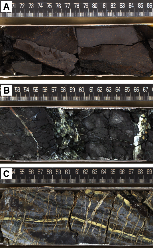
Figure F6. Intensely oxidized and serpentinized dunite pieces, carbonate and serpentine veined harzburgite, and subvertical veins cutting serpentinized peridotite.
Talc-amphibole-chlorite alteration
Talc-amphibole-chlorite alteration is localized and occurs within fault zones, occasionally forming a fine-grained gray zone around serpentinized harzburgite and dunite. These grayish rims are made up of talc, chlorite, and amphibole and increasingly consume the serpentine groundmass (Figure F7), producing a diffuse transition between oxidized serpentinite and talc-amphibole-chlorite schists. In thin section, amphibole is euhedral and coarse grained and forms along the contact with serpentinite, with a dominance of interlayered chlorite and talc inward, away from the contact. In hand specimen, the fine-grained intergrowth of chlorite and talc occasionally has a pale orange-brown color. This type of alteration is absent in samples recovered below Section 8R-1, 84 cm.
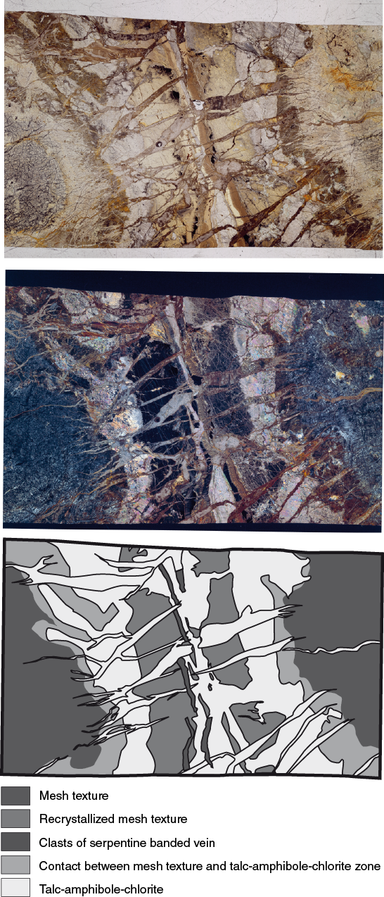
Figure F7. Metasomatic alteration of a possibly originally magmatic vein that subvertically crosscuts serpentinized harzburgite.
Veins and crosscutting relationships
Chlorite-amphibole-talc veins locally cut oxidized serpentinites. These veins are characterized by a composite to banded texture of green, white, and yellow-brown parallel veins, suggesting alternating chlorite-, talc-, and amphibole-rich bands (Figure F7). The veins are perpendicularly crosscut by lens-shaped talc veins, observable at the thin section scale. In Section 4R-1 (and possibly continued in 4R-CC), these subvertical veins are associated with an approximately 8 cm wide green, most likely chlorite-rich zone at the bottom of Section 4R-1. This zone also contains slightly paler green veins, which themselves are cut by a network of very fine black veins. A network of green, branched, most likely serpentine veins crosscuts the oxidized peridotites in Section 5R-1. Carbonate veins occur throughout the entire core but are more abundant in ultramafic rocks and most frequent in the lowest recovered sections (8R-1, 9R-1, and 10R-1). In interval 8R-1, 95–150 cm, oxidized harzburgite is crosscut by a set of white, parallel (almost horizontal) carbonate veins that cut dominantly subvertical green serpentine veins. Further downhole, veining occurs as a dense network of late carbonate veins that cut predating serpentine veins. Locally, up to 8 mm wide carbonate veins with orange cores cut the serpentinite mesh texture as planar veins.
Overprinting relationships
Microscopic observations suggest that serpentinization is the first stage of hydrothermal alteration, which is pervasive and complete throughout the entire hole. Talc-amphibole-chlorite–rich zones overprint the serpentinization texture, which is distinctly visible in thin sections. Serpentinization is also overprinted by pervasive oxidation.
Overview of alteration history
Hydrothermal alteration observed in cores from the three central sites reveals a similar general progression in alteration from serpentinization to talc-amphibole-chlorite metasomatism and later oxidation. However, as such systems remain highly dynamic, complex temporal and spatial relationships exist between the three main alteration types. In addition, alteration heterogeneities provide insight into the scales (<1 m to tens of meters) of the processes operating in the detachment fault. Carbonate precipitation is surprisingly not abundant in these holes, given their close proximity to the Lost City hydrothermal field.
Structure
Site M0076 was drilled closest to the Lost City hydrothermal field (Figure F2), above the slump scarps along the transform wall. It is located near the highest point of the striated surface (see Introduction in the Expedition 357 methods chapter [Früh-Green et al., 2017b]) and is the shallowest site drilled during Expedition 357 (water depth = 768 m). At the site, the striated surface dips gently ≈7° west parallel to the spreading direction and ≈10° north in the across-striation (spreading) direction. No late structures are resolved in the bathymetry disrupting the detachment fault surface at this location.
Two holes were drilled at this site: Hole M0076A to 1.72 mbsf and Hole M0076B to 16.3 mbsf (Figure F3). Hole M0076A recovered breccia with large angular basalt clasts (up to 10 cm) within a consolidated sedimentary matrix. This interval lies above a second one hosting smaller clasts that are either loose or embedded in an unconsolidated greenish matrix. Section 357-M0076B-1-CC comprises loose rubble, including vesicular basalt (see above). No constraint is available on the thickness of the upper structural interval at this hole because of low recovery over the uppermost ≈1.70 m drilled.
The remainder of Hole M0076B includes the following structural intervals:
- An upper complex fault zone from Section 2R-1, to 6R-1, 93 cm (1.7–10.6 mbsf). High-strain deformation is accommodated along schistose horizons rich in talc and/or tremolite that bound structurally continuous core sections of variably altered and veined peridotite (Figure F8). In this hole, schistose fault zones are typically shattered (likely induced by drilling), and no clear observations were made on the geometry of the fault zones and schistosity. Rubble sections of schistose material have thicknesses of several tens of centimeters up to 50 cm (top of Section 4R-1). Clasts of schistose material show folding, in addition to rare small clasts recording brittle deformation within the schistosity, dominated by dolerite.
- Ultramafic units, predominantly harzburgite with minor dunite, all heavily serpentinized. Veining is pervasive, with major subvertical veins crosscut by perpendicular, subhorizontal ones (see above) (Figure F9A). This veining geometry is observed in peridotite sections throughout Sections 3R-1, 4R-1, and 4R-2, which are separated by schistose fault intervals, suggesting general structural continuity. Some subvertical veins accommodate deformation, with weak- to moderate-intensity schistosity developed along their margins and cut by subhorizontal veins.
- Middle fault zone (interval 6R-1, 93–105 cm). The top of this interval is a narrow zone of high-intensity cataclastic deformation in dolerite (preserved in the core at 98–99 cm) that lies above a schistose zone of tremolite, and the bottom is a fine-grained breccia with clasts (submillimetric; 103–105 cm) embedded in an unconsolidated matrix (gouge?) (Figure F9A). X-ray diffraction (XRD) analysis from the gouge interval is dominated by talc with lesser chlorite and clinochrysotile (Figure F10). The zone is in contact with a deeper zone of high-intensity schistosity with deformed metagabbro clasts.
- Lower fault zone (interval 6R-1, 105 cm, to the bottom of the hole). As in the upper fault zone, this interval shows zones of schistose tremolite and/or talc with reworked clasts of variable size (from >10 cm to submillimetric; e.g., interval 8R-1, 60–80 cm). These schistose levels are less abundant and thinner than those above.
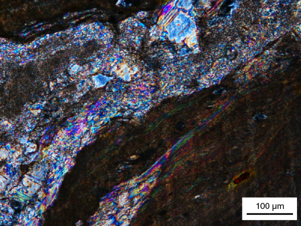
Figure F8. Amphibole- and talc-bearing shear zone.
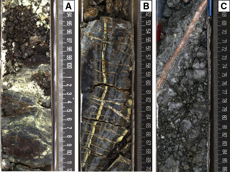
Figure F9. High-intensity cataclastic deformation in dolerite, steeply dipping composite amphibole and chlorite (± talc) vein cutting serpentinized porphyroclastic harzburgite, and moderately dipping carbonate vein with oxidation cutting pyroxene-poor serpentinized dunite.
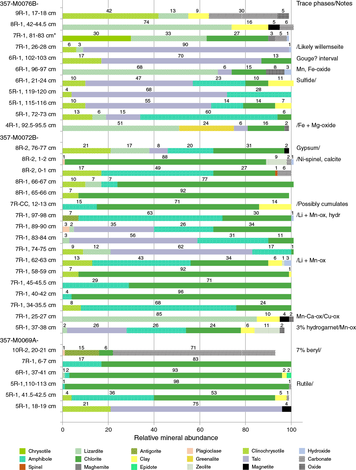
Figure F10. Mineral phases identified by bulk powder XRD analysis, Holes M0076B, M0072B, and M0069A.
Coherent units of harzburgite up to ≈1 m in length are heavily serpentinized and, as in the upper fault level, commonly show moderate to steeply dipping veins (Figure F9B, F9C). This lower peridotite unit is very fragile and shows heavy fracturing (oxidized) but is coherent and well preserved in the proximity of magmatic veins. No examples of schistose or cataclastic serpentinite were observed.
Site M0072
Rock types and igneous petrology
Site M0072 is located near the summit of the striated detachment fault surface (Figure F2). Hole M0072A (two cores) penetrated the uppermost 2.20 mbsf and recovered carbonate sand and sedimentary breccia consisting of clasts of basalt in a carbonate matrix (Figure F3). Hole M0072B (eight cores) penetrated to 12.43 mbsf and recovered the same sedimentary breccia as Hole M0072A, allowing this unit to be correlated across the two holes. Core 357-M0072B-4R had no recovery. In contrast to many other sites, Site M0072 is dominated by mafic lithologies as opposed to ultramafic ones; Hole M0072B also contains abundant rodingite intervals.
The upper sections of both holes consist of surficial features including carbonate sands (with centimeter-scale subrounded basaltic lithic fragments), sedimentary basaltic breccias, and basaltic rubble (with rare oxide gabbro fragments observed in Hole M0072B). Deeper intervals were cored in Hole M0072B, including rubble sections of mixed composition (metabasalt, metagabbro, and serpentinized harzburgite) that occur in Sections 3R-1 through 5R-1, Unit 1. These rubble sections overlie a principally continuous section of alternating talc-amphibole schists, rodingites, and serpentinized harzburgites (Section 5R-1, Unit 3, to the bottom of the hole in Section 8R-2). The igneous petrology of Holes M0072A and M0072B is summarized on a core-by-core basis below (see VCDs in Core descriptions).
Hole M0072A
Core 357-M0072A-1R consists of four units. Unit 1 comprises carbonate sand with 1–3 cm subrounded basalt fragments. The fragments are nonvesicular to sparsely vesicular and occasionally are oxidized along clast edges or contain a manganese crust. Core 1R, Units 2–4, is composed of basaltic breccia with a dark carbonate matrix (varying in degree of consolidation and fracturing).
Core 2R contains a number of rubble fragments of basalt and minor olivine basalt. The basalt is nonvesicular, has a microcrystalline matrix, and contains phenocrysts of plagioclase, olivine, and clinopyroxene.
Hole M0072B
Core 357-M0072B-1R consists of sedimentary basaltic breccia. The uppermost unit contains fossiliferous sand with rare fragments of angular basalt. This overlies basaltic breccia (Unit 2) and mixed rubble with fragments of basalt and breccia (Unit 3). Unit 2 includes two types of unconsolidated basalt fragments: Type 1 basalt has subangular to rounded vesicles (<1%) and an aphyric matrix, whereas Type 2 basalt has rounded vesicles (commonly infilled; i.e., amygdules) and a fine-grained matrix.
Core 2R is composed of basaltic rubble (interval 2R-1, 0–35 cm, Units 1 and 2) and oxide gabbro (interval 2R-1, 35–59 cm, Unit 3). Unit 1 basaltic rubble contains altered basalt and olivine basalt, and Unit 2 basaltic rubble consists of altered vesicular basalt fragments commonly infilled as amygdules. Unit 2 basalts also contain sulfides up to 2 mm in diameter. Unit 3 oxide gabbro is medium to coarse grained with ≈4–10 mm plagioclase, 4–6 mm clinopyroxene and oxides, and subophitic texture. Plagioclase and clinopyroxene make up ≈60% and ≈40% of the mode, respectively. Some variations are observed in thin section. The oxide gabbro in Sample 2R-1, 49–53 cm, contains 80% plagioclase (maximum = 7 mm; average = 4 mm), 15% clinopyroxene (0.5–3 mm), and 5% oxides (0.1–4 mm). Subhedral to anhedral plagioclase grains show subequant to tabular habits. Clinopyroxene and oxides are interstitial to plagioclase grains.
Core 3R contains mixed rubble with fragments of greenish gray metabasalt, metagabbro, and serpentinized harzburgite.
Core 5R consists of three units. Unit 1 comprises (mostly) well-rounded fragments of serpentinized harzburgite and metabasalt, and Unit 2 comprises moderately sorted talc-rich sediments with rounded basalt clasts. Unit 3 is talc-amphibole schist containing boudinaged dolerite fragments.
Core 6R is composed of six units of talc-amphibole schist, rodingites, dolerite, and dunite. Unit 1 (interval 6R-1, 0–12 cm) consists of rodingite and talc-amphibole schist fragments; the protolith of the rodingite is likely a gabbro. Unit 2 (interval 6R-1, 12–26 cm) is rodingitized gabbro. Unit 3 (interval 6R-1, 26–45 cm) is talc-amphibole schist but encompasses dolerite clasts. Unit 4 (interval 6R-1, 45–65 cm) consists of serpentinized dunite, whereas Unit 5 (interval 6R-1, 65–70 cm) comprises a thin interval of rodingitized gabbro. Unit 6 corresponds to a talc-amphibole-chlorite interval.
Core 7R is composed of five units including talc-amphibole-chlorite schist, serpentinized dunites, and harzburgites. Unit 1 consists of talc-amphibole-chlorite schist rubble and angular to rounded serpentinite clasts. Unit 2 contains serpentinized dunite with very fine grained mesh texture. Unit 3 is talc-amphibole-chlorite schist but contains two regions of brown alteration in intervals 7R-1, 37–40 and 53–59 cm, which possibly represent gabbro rodingitization. Unit 4 consists of mesh-textured serpentinized harzburgite with 1–4 mm long bastites (≈5% modal abundance). Unit 5 is talc-amphibole-chlorite schist that contains rodingitized gabbro. Section 7R-CC is composed of three angular pieces of partially rodingitized gabbro.
Core 8R contains rodingitized gabbro (Unit 1), serpentinized harzburgite (Unit 2), talc schist (Unit 3), and serpentinized porphyroclastic harzburgite with mesh texture (Section 8R-2, Unit 4). The rodingitized gabbro is medium to coarse grained and strongly foliated. The gabbro contains 3 mm plagioclase laths (≈20%) and 5 mm blocky clinopyroxene (30%). The talc schist (Unit 3) exhibits a thin (≈6 cm) interval of serpentinized harzburgite in interval 8R-1, 60–66 cm.
Alteration
Four types of alteration were observed in Hole M0072B: serpentinization, talc-amphibole-chlorite metasomatism, oxidation, and rodingitization (Figure F11). Talc-amphibole-chlorite metasomatism is the most common alteration type and is present throughout the hole. Serpentinization is the second most abundant alteration type and increases in abundance below 8 mbsf. Rodingitization is restricted to some mafic intervals between 7.7 and 9.9 mbsf. Oxidation developed at the top of the hole and between 9.1 and 9.7 mbsf.
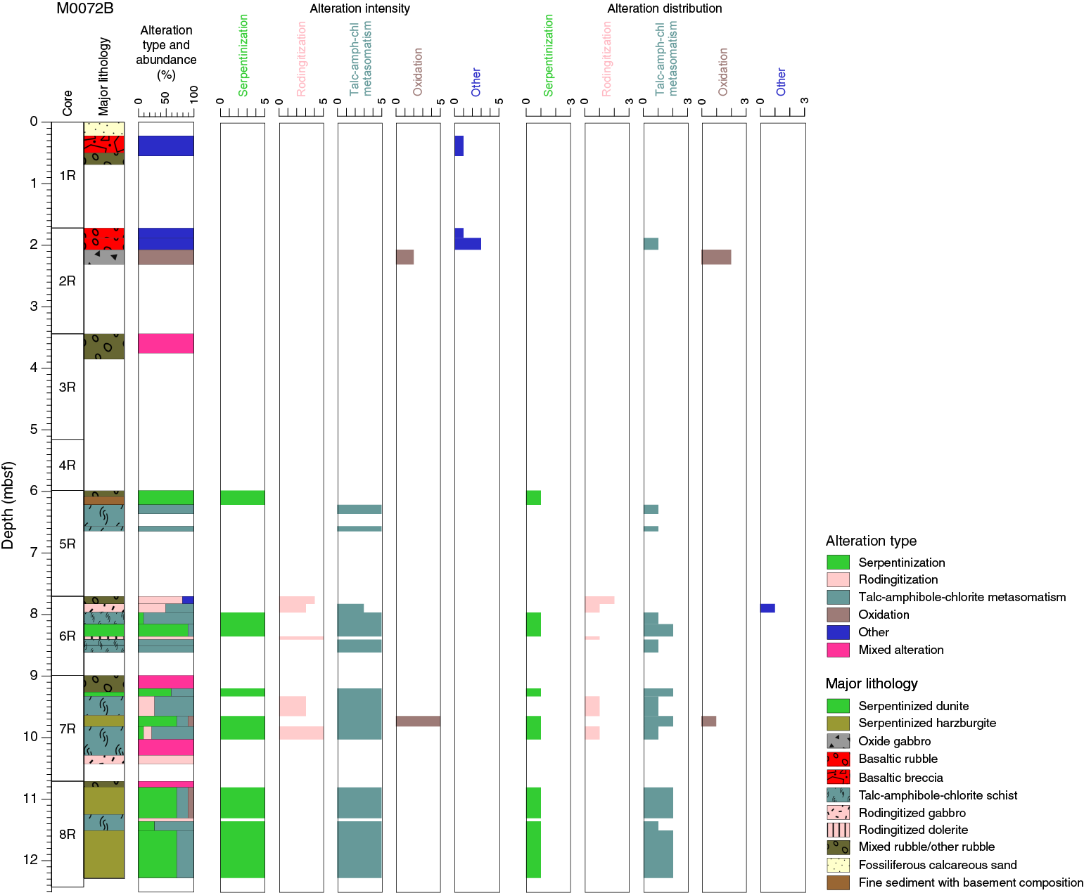
Figure F11. Alteration, Hole M0072B.
Alteration intensity increases overall in the uppermost 6 m of Hole M0072B from slightly altered to totally altered regardless of alteration type. Below 6 mbsf, the alteration intensity is predominantly classified as complete with discrete intervals of moderate alteration generally associated with rodingitization.
Above 6 mbsf, talc-amphibole-chlorite metasomatism is predominantly present as pervasive alteration, and below 6 mbsf, a combination of pervasive and localized alteration is observed. Serpentinization is pervasive.
Serpentinization
Serpentinization is predominantly dark green with some pale green to brown areas associated with areas of oxidation and is typically pervasive throughout the core. No primary minerals were observed, with the exception of relict Cr spinel. Textures range from mesh to hourglass. Magnetite is mainly concentrated in the mesh rims. Late serpentine veins are very common. In Hole M0072B, talc-amphibole-chlorite veins frequently crosscut areas of serpentinization, with a spacing on the order of tens of centimeters. The longest core interval displaying alteration dominated by serpentinization is a 25 cm interval in Section 8R-1.
Talc-amphibole-chlorite metasomatism
Talc-amphibole-chlorite metasomatism is pale green to white and occurs as both deformed schists and undeformed veins. Talc-amphibole-chlorite metasomatism overprinted the previous serpentinization and shows different assemblages and variable mineral abundances from one area to one other. An XRD profile through Section 357-M0072B-7R-1 shows alternation between a chlorite-rich zone (± amphibole), an amphibole-rich zone (± talc), and a talc-rich zone (± amphibole) (Figure F12). The chlorite-rich alteration, which is deep green, appears to always be spatially associated with mafic rocks. The metasomatic assemblage after serpentinite typically consists of sigmoidal areas made by larger broken amphibole crystals in a fine matrix of fine-grained acicular elongated amphibole (± chlorite) wrapped by a very fine grained foliated talc-rich groundmass.
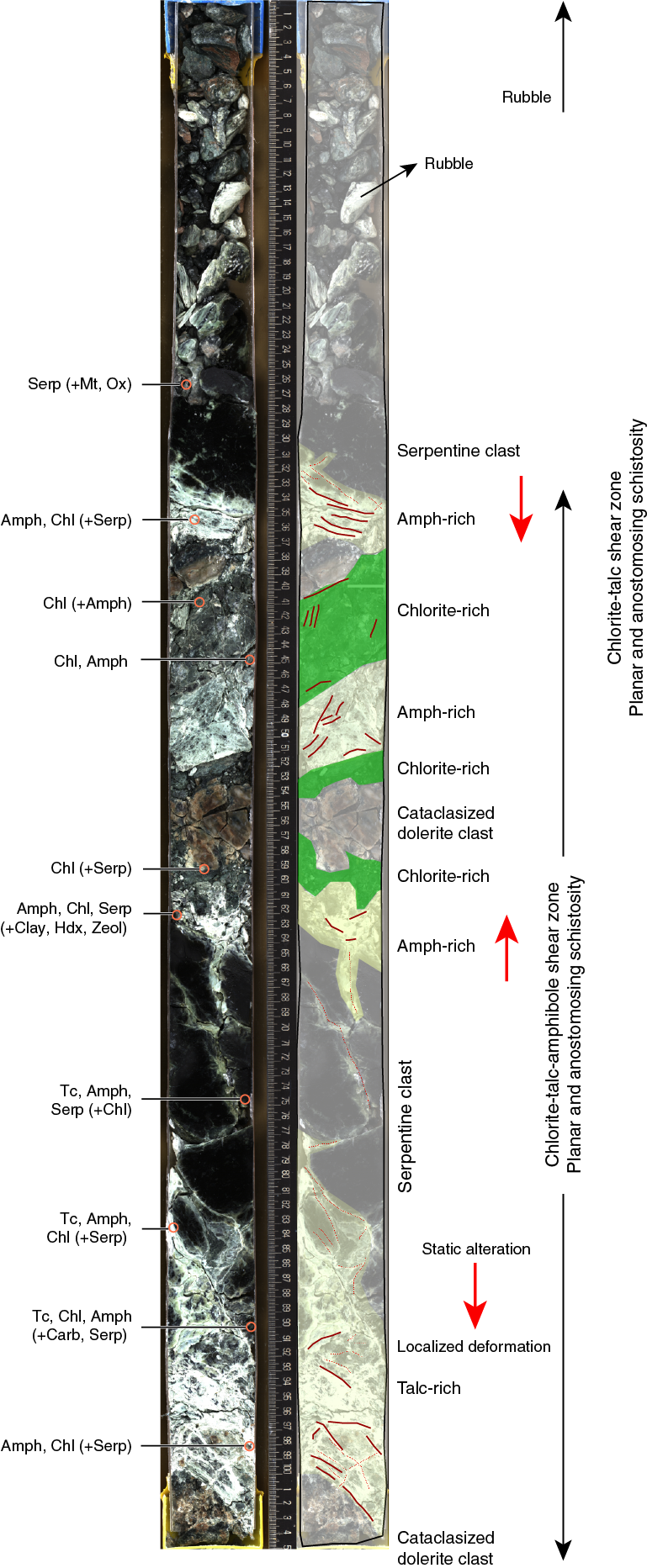
Figure F12. Complex shear zone showing a transition from static alteration to strain localization in alternating talc-, amphibole-, and chlorite-rich shear zones.
In Section 8R-1, the contacts between mafic and serpentinized ultramafic lithologies are preserved and appear to be zones of preferential alteration, as shown by the development of green and white metasomatic veins or zones (Figure F13). Green alteration (chlorite rich ± talc and amphibole) seems to follow the mafic unit that intruded the ultramafic protoliths subhorizontally, whereas talc-rich, white alteration is restricted to the serpentinites. The talc veins branch outward from the main zone of white alteration, and patches of whitish talc-rich areas extend into the rocks. These may mark preferential flow pathways. The final result is a complex network of metasomatic, fine-grained domains and veins exhibiting static to foliated patterns, leaving only limited areas that preserve the initial serpentinization textures.
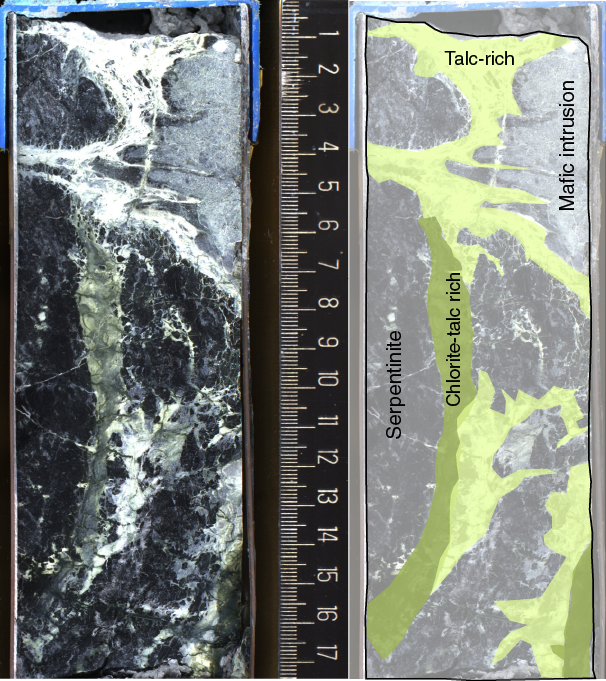
Figure F13. Magmatic intrusion into a fully serpentinized harzburgite. Late metasomatic alteration at the boundary of the mafic/ultramafic rocks produced a white and green talc-amphibole-chlorite assemblage that crosscuts the previous texture.
Oxidation
Oxidation in Hole M0072B was mainly recognized in thin sections and is restricted to late oxidation associated with metasomatic veins (Figure F14).

Figure F14. Serpentinite partially metasomatized to chlorite-amphibole-talc.
Rodingitization
Rodingitization occurs as pale brown to pinkish intervals (≈5 cm thick). Sections 357-M0072B-6R-1 and 7R-1 (Figure F12) show exceptional relationships between rodingite, talc ± amphibole-rich zones, and serpentinized harzburgite. Rodingites are the alteration products of gabbroic veins/lenses that intruded harzburgitic protoliths and are concentrated at the contact between the two lithologies. The altered mafic intrusions commonly show an external domain made mostly of chlorite (chlorite blackwall), whereas the light pink internal domain seems to be completely altered to a mix of chlorite and other fine-grained mineral assemblages that may include hydrogarnet.
Veins and crosscutting relationships
Hydrothermal veins are present throughout Hole M0072B and range in composition and distribution. Veins are generally 1–5 mm in width, predominantly with an irregular shape, and form branches or vein networks. Overall, the vein mineralogy is dominated by talc with chlorite/amphibole mixtures. Crosscutting vein relationships reveal that the multiple vein types do not show a consistent temporal evolution because talc veins are cut by amphibole veins but amphibole veins are also cut by talc veins.
Overprinting relationships and alteration history
Excluding the uppermost few meters of basaltic breccia and mafic rubble, Hole M0072B represents a harzburgite-dominated fault zone. Pervasive and complete serpentinization of harzburgite is overprinted by late Si-rich metasomatism that is variable between localized and pervasive and between static to foliated. Mafic intrusions are highlighted by chlorite blackwall domains that grade into talc-amphibole–rich areas close to the serpentinites. The irregularity of the crosscutting vein relationships emphasizes the dynamic multiphase nature of the system with similar composition of veins forming at multiple times. The alternation of the metasomatized and serpentinized domains, together with complex alteration textures, points to multiple pulses of Si-rich fluids into this part of the detachment fault.
Structure
Site M0072 is located near the summit of the striated detachment fault surface, ≈750 m north-northwest of the Lost City hydrothermal field (Figure F2). The site is on the flank of a gentle (10°N) slope that corresponds to the wall of a bathymetric striation (see Introduction in the Expedition 357 methods chapter [Früh-Green et al., 2017b]). No late structures that disrupt the detachment fault surface at this location are resolved in the bathymetry. Two holes were drilled at this site: Hole M0072A was cored to 2.2 mbsf and recovered 0.87 m; Hole M0072B penetrated to 12.43 and recovered 6.49 m of rock. Both holes have a shallow structural interval of sediment and rubble, and two deeper intervals attributed to fault zone were observed in Hole M0072B core.
The shallow structural interval comprises the entirety of Hole M0072A and Cores 357-M0072B-1R through 5R to ≈6.2 mbsf. The recovered cores in this interval record no contact relations and either are not in situ or are rubble on top of the basement. The shallow structural interval comprises unconsolidated sands and coarser sediment and includes the following, from top to bottom:
- Unconsolidated sand (0 to ≈0.4 m in both holes) containing angular clasts (primarily basalt) in a carbonate matrix with foraminifers. Consolidated breccia with an orange to gray matrix was recovered in interval 357-M0072A-1R-1, 40–50 cm. Below the breccia, the cores are composed of loose, unconsolidated rubble with no trace of sedimentary material or carbonate matrix. Clasts are dominated by basalt with minor gabbro and variably serpentinized peridotite. No contacts are preserved. This structural interval is considered not in situ.
- Fine-grained interval of cataclasis (possible fault gouge). Core 357-M0072B-5R was drilled through a 15 cm thick zone (interval 5R-1, 13–23 cm; 6–6.15 mbsf) of fine breccia with clasts ranging in size from a few millimeters to submillimeter (Figure F15). The matrix comprises unconsolidated greenish gray material and shows through-going structures (faint layering or lineaments over >2 cm), suggesting structural continuity without drilling disruption. Clasts are polymict, containing both dolerite and sheared talc-rich, variably schistose material similar to that found below.
- A complex fault zone recovered below Section 5R-1, 26 cm. This zone shows schistose, highly foliated regions of high strain with moderate to gentle dip (typically <45°) separating intervals of variably serpentinized peridotite (occasionally with magmatic impregnation). The serpentinite intervals commonly exhibit talc-amphibole-chlorite alteration. Several intervals of 5–15 cm thick rodingitized dolerite occur in this hole. In interval 6R-1, 18–24 cm, this rodingitized dolerite locally has a strong mylonitic fabric. Talc- and amphibole-rich schistose zones are continuous over core lengths of 13 to 34 cm (Figure F15) and often include cataclastically deformed dolerite and possibly serpentinized peridotite, with other rock types that were not identified. In the thicker schistose units, the fault zone shows an anastomosing structure with a complex set of crosscutting, small-scale shear zones and local folding of schistosity.
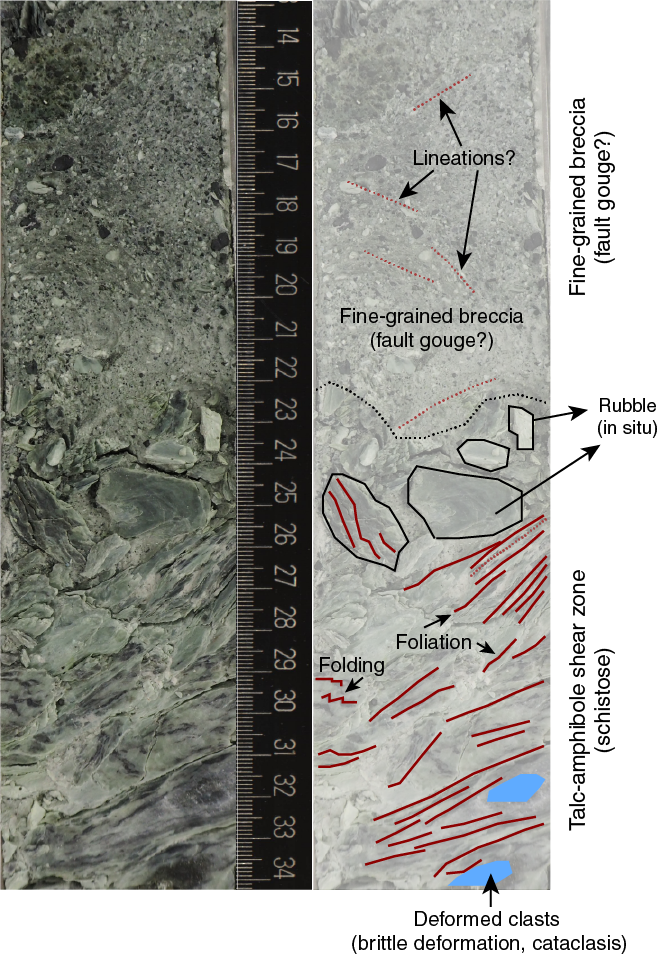
Figure F15. Fine-grained breccia in contact with a schistose talc-amphibole shear zone hosting brittlely deformed clasts of metadolerite.
Serpentinized peridotite within the shear zone shows structural continuity over core lengths of >50 cm and displays early deformation locally, including magmatic and later pale green or white metamorphic veining with talc and amphibole. The edges of the serpentinized blocks in contact with adjacent schistose fault zones show a gradient in the intensity of both alteration and deformation. Static alteration is observed away from main veins and at the edges of clasts; deformation gradually overprints this static alteration (Figure F12), forming schistose shear zones that locally display intense cataclasis of other rock types reworked in the fault zone (Figure F16). A feature in this core not seen at the eastern sites (M0068 and M0075) is strong deformation of talc-rich zones without clear localization between talc and tremolite in the core as a whole. Strongly deformed zones in serpentinite without talc or tremolite were not seen.

Figure F16. Serpentinized peridotite.
Site M0069
Rock types and igneous petrology
Site M0069 is the northernmost of the three central sites near the Lost City hydrothermal field (Figure F2). The site is located in a corrugation trough at the base of a north-facing slope with a relief of approximately 100 m (see Introduction in the Expedition 357 methods chapter [Früh-Green et al., 2017b]). Immediately north of the site is a steep mass-wasting scarp dissecting the corrugated surface. The Lost City hydrothermal field lies approximately 1 km due south along the transform wall.
A single hole (M0069A) was drilled at this site, penetrating 16.44 mbsf and recovering 12.29 m of rock in 10 cores (Figure F3) with a total overall recovery of 75% (one core with no recovery). Recovered rocks include serpentinized harzburgites, lesser serpentinized dunites, metagabbros, and metadolerites. The upper four cores of the hole contain carbonate sand transitioning into a loose rubble unit dominated by angular fragments of serpentinized harzburgite (Section 5R-1, Unit 1; fragments up to 4 cm). Coherent sections of serpentinized harzburgites (5% bastite after orthopyroxene) with observable mesh textures are observed below (Section 5R-1, Unit 2). A large portion of the remaining cores is dominated by metadolerite (Sections 5R-1, Unit 3, through 9R-1, Unit 2) and rubble sections. Metadolerite is generally aphyric and microcrystalline to fine grained (typically 0.2–0.5 mm); some sections exhibit larger clinopyroxene (up to 1 mm) and disseminated sulfides (<1 mm). The lower sections of the hole (9R-1, Unit 3, through 10R-3) contain alternating serpentinized harzburgites and serpentinized dunites; the harzburgites exhibit relict orthopyroxene (bastites; up to 10 mm and typically with a modal abundance of 10%–15%), and the dunites typically contain chromian spinel. The igneous petrology of Hole M0069A is summarized on a core-by-core basis below (see VCDs in Core descriptions).
Cores 1R, 2R, and 3R consist entirely of calcareous sand with rare small lithic fragments (<2 mm); Core 4R had no recovery.
Core 5R contains loose rubble with angular fragments (up to 4 cm) of mostly serpentinized harzburgite (Unit 1), a coherent piece of coarse-grained serpentinized harzburgite (Unit 2), and alternating metagabbro and metadolerite (Unit 3). In the coherent harzburgite, relict or altered orthopyroxene is granular and anhedral, ranging from 3 to 7 mm and occupying 5% of the mode. In regions of pale gray alteration, mesh texture is recognizable. Within Unit 3, a metagabbroic to metadoleritic unit (20–29 cm) is followed by intervals of metadolerite (29–35 cm) and metagabbro (35–49 cm). These intervals are followed by an interval of metadolerite at 62–83 cm and lighter toned dolerite at 83–115 cm. Approximately 1 mm diameter clinopyroxene and submillimeter disseminated sulfides were observed; plagioclase was not observed at the macroscale due to the small grain size. The metagabbro contains 1–3 mm subhedral, tabular plagioclase and 3–7 mm anhedral and granular clinopyroxene.
Core 6R consists of two sections. Section 6R-1 is divided into two units, the first containing metadolerite rubble and the second a coherent section of drilled metadolerite. Generally, dolerite is fine grained (e.g., 29–42 cm) with two localized (10 mm × 20 mm) patches of coarser material (37–42 cm, possible metagabbroic material). Dolerites in this section exhibit characteristic patchy alteration surrounding epidote veins. The underlying section (6R-2) also contains metadolerite crosscut by a network of epidote veinlets and altered locally to an assemblage dominated by chlorite.
Core 7R is divided into three units, the first (interval 7R-1, 0–8 cm) consisting of rubble dominated by dolerite and amphibole-chlorite schist. Unit 2 (interval 7R-1, 8–22 cm) consists of fractured talc-amphibole-chlorite schists. The last unit (interval 7R-1, 21–70 cm) is a metadolerite that is generally highly fractured with intact pieces of dolerite found mainly in interval 7R-1, 35–45 cm. Primary grain size increases in Section 7R-1 from 21 to 40 cm (away from the amphibole-chlorite schist); no chilled margin was observed at the macroscale.
Section 8R-1 is a more coherent section continuing from Core 7R, and it comprises fine-grained, fractured metadolerite overlying talc-amphibole-chlorite schists. The metadolerite is aphyric and microcrystalline (0.1–0.5 mm) and relatively fresh.
Core 9R consists of two sections. Section 9R-1 contains metadolerite rubble (Unit 1), polymict breccia (Unit 2), and serpentinized harzburgite (Unit 3). Section 9R-2 is characterized by alternating units of serpentinized harzburgite and serpentinized dunite and is divided into four units. Unit 1 (0–61 cm) comprises moderately oxidized serpentinized harzburgite with visible bastites. Unit 2 (61–77 cm) consists of oxidized serpentinized dunite with occasional mesh textures, but no recognizable orthopyroxene is apparent in the dunite. Some chromian spinels are found as aligned trains. Unit 3 is serpentinized harzburgite, as described above. Unit 4 is serpentinized dunite, as described above, but is less oxidized.
Core 10R consists of three sections. Sections 10R-1 and 10R-2 comprise serpentinized harzburgite, and Section 10R-3 comprises serpentinized dunite. Section 10R-1, Unit 1 (0–10 cm), is oxidized, mesh-textured serpentinized harzburgite rubble with protogranular orthopyroxene grains (≈5.5 mm; 15% modally). Section 10R-1, Unit 2, consists of fractured but intact serpentinized harzburgite. The serpentinized harzburgite of Section 10R-1, Unit 3, is pyroxene rich and contains protogranular and altered orthopyroxene (relict grains up to ≈10 mm with a modal abundance of 25%–30%; possibly with some minor clinopyroxene). Section 10R-2, Unit 1 (0–24 cm), consists of pyroxene-rich serpentinized harzburgites (25%–30% relict pyroxene, similar to Section 10R-1, Unit 3, above); Section 10R-2, Unit 2, consists of serpentinized dunite. Section 10R-3 also comprises serpentinized dunites, but they are less oxidized than those in Section 10R-2, Unit 2, and contain equant chromian spinel trains. The chromian spinel trains and disseminated patchy spinel-rich zones are only found in serpentinized dunite units (although isolated chromite is observed within serpentinized harzburgites). In places, chromian spinels may retain protolithic compositions based on microscopic observation (an example from a harzburgite is shown in Figure F17); chromite rims are typically altered into an opaque oxide (likely ferrite-chromite).
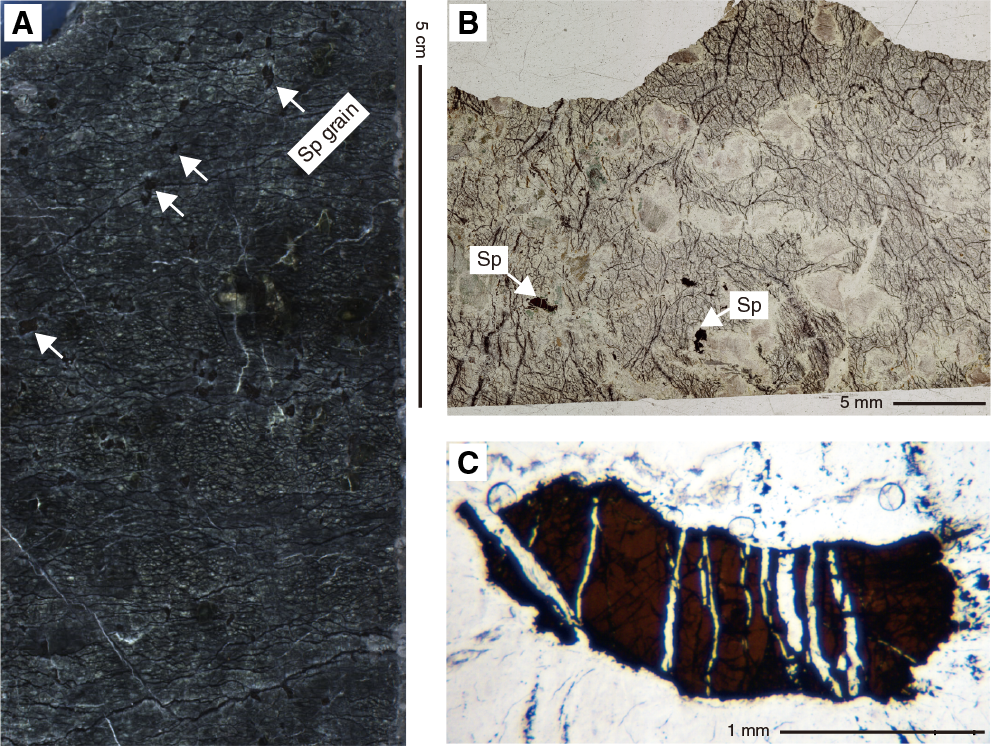
Figure F17. Serpentinized harzburgite with chromian spinel grain.
Alteration
The uppermost sections of Hole M0069A consist of sediment to 6.88 mbsf. Below this depth is small interval (5R-1, 12–20 cm) of metasomatized harzburgite, metadolerites with intervals of talc-amphibole-chlorite–rich sections, and entirely serpentinized harzburgites and dunites (Figure F3). A polymict breccia interval (13.12–13.29 mbsf) marks the transition between the metadolerites and serpentinites. Overall, four types of alteration were observed: hydrothermal alteration of dolerites and locally gabbros (classified as “other”) to metadolerites and metagabbros, respectively; serpentinization; oxidation; and talc-amphibole-chlorite metasomatism (Figure F18). Hydrothermal alteration of dolerites and gabbros includes three intervals of talc-amphibole-chlorite–rich rocks (7.01–7.08, 10.4–10.53, and 11.67–13.32 mbsf). Serpentinization dominates the ultramafic portion and is associated with extensive oxidation. Dolerites and gabbros are generally only slightly to moderately altered, whereas talc-amphibole-chlorite metasomatism in the mafic intervals is complete. The ultramafic piece at the top of the metadolerites is pervasively and highly metasomatized (predominantly to talc). Harzburgites and dunites are completely serpentinized and slightly oxidized. The distribution of dolerite and gabbro alteration is variable. The alteration types classified as “other” are usually pervasive, with the exception of one localized and one patchy occurrence of talc-amphibole-chlorite metasomatism (Figure F19A).
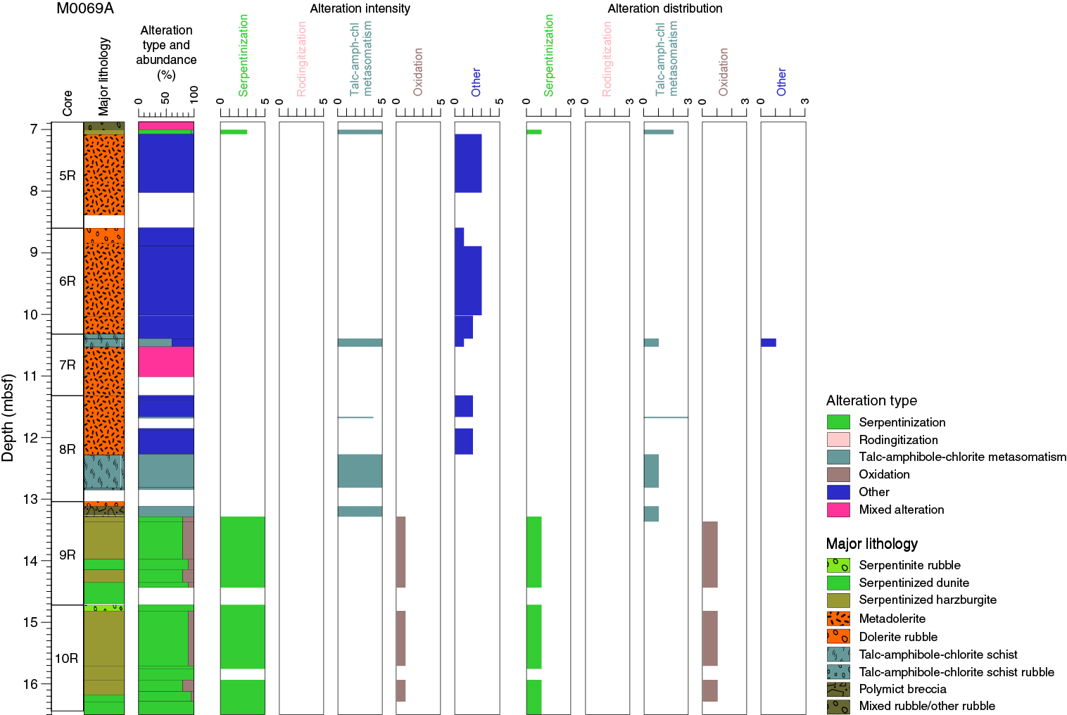
Figure F18. Alteration, Hole M0069A.
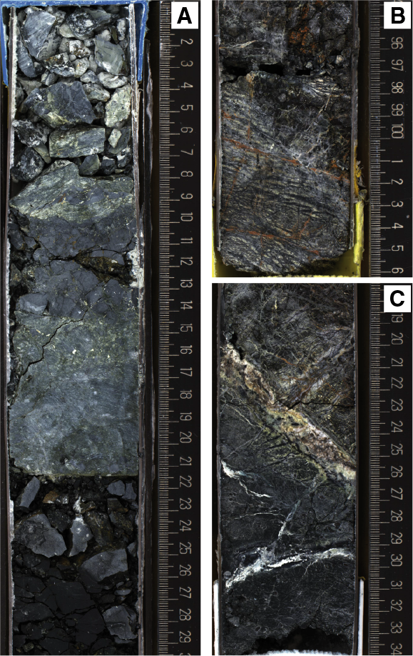
Figure F19. Amphibole-chlorite zone with large metadolerite clast, serpentinized dunite presenting a mesh to ribbon texture underlined by preferentially oriented magnetite concentrations along microfractures, and serpentinized dunite crosscut by multiple carbonate veins bordered by significant oxidation.
Hydrothermal alteration of dolerites and gabbros (classified as “other”)
Dolerites in the upper sections of Site M0069 cores have all undergone hydrothermal alteration. The dominant background alteration color is pale gray, and alteration halos and patches are pale brown to green. Throughout Sections 357-M0069A-5R-1 through 6R-2, irregular pale brown-green alteration patches are abundant and represent more than half the cut surface (Figure F20). In Sections 7R-1 to 8R-1, 93 cm, dolerite has pale gray background alteration. The abundance of brown halos dramatically decreases, and, where present, they are restricted to around veins or fractures. In thin section, the background alteration is dominated by chlorite and amphibole replacing plagioclase and clinopyroxene, respectively. Plagioclase is extensively replaced with ≈15% primary plagioclase remaining; however, clinopyroxene is totally replaced by amphibole. In thin section, alteration patches are dominated by chlorite and amphibole, as suggested by XRD analyses.
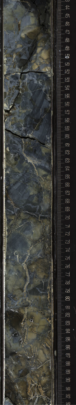
Figure F20. Alteration of pale, irregular, patchy alteration observed in metadolerites. Yellow-brown patches are chlorite rich and cut by epidote veins.
Serpentinization
Serpentinization is the dominant alteration type at the base of Hole M0069A in Sections 9R-1, 9R-2, and 10R-1. These sections comprise serpentinized harzburgite and dunite. Serpentinization is pervasive, and no primary minerals are preserved other than Cr-rich spinel. In hand samples, a well-recognizable mesh-to-ribbon texture was observed, reflected by networks defined by concentrations of magnetite along the mesh rims or parallel bands of magnetite, respectively (Figure F19B). Locally intense recrystallization of serpentine occurs along purple-black corridors. Serpentinized harzburgites are clearly distinguished from dunites based on the presence and abundance of bastites. In thin section, the serpentine-magnetite mesh texture to local ribbon texture is well preserved. Bastites mostly consist of chlorite and amphibole with local talc rims. Chlorite is also locally present as bands within the mesh texture and around spinel.
Oxidation
In Hole M0069A, oxidation is mostly restricted to the ultramafic units. Although metadolerites may be slightly oxidized, such alteration was not evident macroscopically. In serpentinites, it develops pervasively and more intensely along veins and fractures (Figure F19C), locally producing a halo that borders the veins. In addition, a few carbonate veins comprise an orange vein-core, suggesting the presence of iron hydroxides. The degree of oxidation ranges from slight to high and decreases with increasing depth. In the lowermost drill core, oxidation is almost entirely absent.
Talc-amphibole-chlorite metasomatism
Talc-amphibole-chlorite metasomatism is present in one interval in Hole M0069A (5R-1, 12–20 cm) where a serpentinized harzburgite is pervasively and very highly metasomatized to mostly talc. In addition, talc-amphibole-chlorite–rich zones are present in Sections 8R-1 and 9R-1 and are associated with localized horizons of intense deformation.
Veins and crosscutting relationships
Both metadolerites and serpentinites are highly veined. In dolerite, veins are yellow-brown and composed of epidote as determined by optical microscopy and XRD. They are typically localized within specific intervals and have a fine-grained yellow-brown halo composed of chlorite and epidote (Figure F20). In serpentinite, carbonate veins and serpentine veins are present. Local recrystallization of serpentine occurs, producing dark purple fine-grained bands that are cut by later carbonate veins. Carbonate veins are as wide as 8 mm and range from fine vein networks to planar veins. They range in vein structure from uniform to banded to composite with abundant Fe oxide–rich cores. In interval 10R-2, 20–27 cm, a 1.4 cm wide polycrystalline vein cuts the serpentinite. The vein mostly consists of carbonate with traces of chlorite and serpentine. Locally, the vein also contains remnants of magnetite-vein fragments.
Overprinting relationships and alteration history
Initial interpretation suggests that dolerites possibly intruded talc-amphibole-chlorite schists, overprinting the mineralogy and texture of the previous fault rocks but also producing a slightly brecciated contact between the mafic and ultramafic rocks. Complete serpentinization of the ultramafic rocks and high degrees of oxidation suggest that these serpentinites were exposed to extensive fluid circulation with late formation of carbonate veins. In contrast, the overlying metadolerites show patchy and localized alteration and lower degrees of oxidation.
Overview of mineralogy from XRD data
Samples for XRD analysis were taken from three different holes at each of the three central sites (Figure F10). The most commonly identified phases were secondary minerals, namely serpentine (mainly lizardite and [clino-]chrysotile), talc, amphibole, and chlorite. Chlorite is the dominant phase in Hole M0069A samples, sometimes occurring in proportions >90%. Chlorite is also dominant in many Hole M0072B samples, whereas Hole M0076B is dominated by talc and serpentine, where they are the most frequent and abundant (Table T2). In Holes M0072B and M0069A, significant amounts of talc were only detected in intervals 357-M0072B-7R-1, 74–90 cm, and 357-M0069A-5R-1, 18–19 cm. Amphibole was also frequently detected and occurs in significant proportions in Hole M0072B. Essentially no primary phases were detected in any of the samples analyzed. Carbonate occurs as a minor phase in some samples and is a major component of two shallow samples, one from Hole M0069A and one from Hole M0076B. Other minor phases detected include spinel, magnetite, hydrogarnet, clay, zeolites, Mn/Fe oxides, and hydroxides.
Table T2. X-ray diffraction results, Holes M0069A, M0072B, and M0076B. Download table in .csv format.
Structure
Structural features divide Hole M0069A into distinct structural intervals. The upper structural interval (0–6.5 mbsf; Sections 1R-1 through 4R-1) is composed of unlithified calcareous sediment (sand/ooze) with foraminifers and shows no internal structure. A single basaltic clast is found in Section 1R-1 at 0.85 mbsf.
The lowermost 10 m of core exhibits three distinct structural units hosting several shear zones bounding intervals of dolerite and serpentinized dunite (Figure F21).
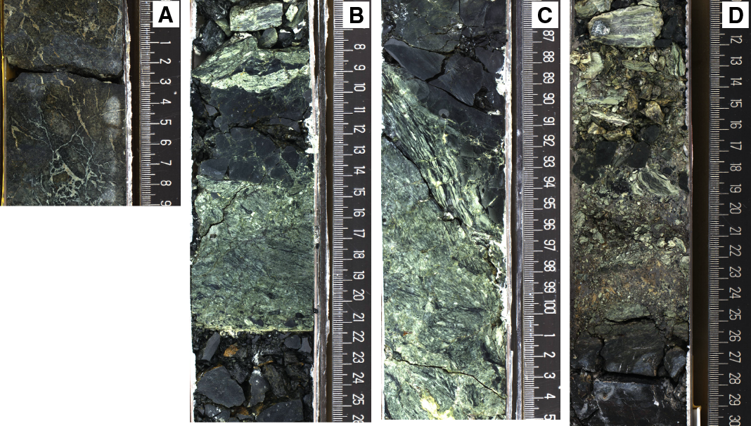
Figure F21. Deformation and dolerite intrusion, Hole M0069A.
Structural Unit A
Structural Unit A is rubble (interval 5R-1, 0–20 cm). Clasts include serpentinized harzburgite (>5 cm) and smaller clasts of various compositions. Some clasts show weak foliation and may correspond to a shear zone at the top of the core. Below this rubble interval, the core is relatively coherent and comprises structural Units B and C.
Structural Unit B
Structural Unit B is a fault zone including deformed and altered doleritic intervals (interval 5R-1, 20 cm, to 9R-1, 26 cm; ≈6.9–13.3 mbsf). This structural unit includes highly schistose, coherent shear zones (interval 8R-1, 88–150 cm) with both consolidated and unconsolidated matrix material (interval 6R-1, 0–40 cm).
Structurally continuous intervals of dolerite are bound by shear zones or faults and show various types of alteration and deformation intensity. Dolerite often has pervasive epidote veining (interval 5R-1, 39–50 cm) of variable intensity but is always associated with moderate to intense cataclasis (Figure F21). Typically, coherent metadolerite intervals (30 and 130 cm thick) are bound above and below by intervals of breccia that may or may not include talc-tremolite-chlorite schist. Locally, subhorizontal foliation was observed; late thin faults and fractures cut the preexisting zone of cataclasis and veining. Cataclastically deformed dolerite is cohesive, likely cemented by secondary minerals. Breccias and schistose zones sometimes include clasts of dolerite from >10 cm to submillimetric in size. Importantly, this unit contains an intrusive contact between dolerite and fault rocks, showing that dolerite intrusion was synkinematic.
Core 6R contains fine-grained breccia with angular clasts in an unconsolidated matrix (interval 6R-1, 20–30 cm) (Figure F22). This breccia interval lies above a relatively undeformed but shattered (likely drilling induced) metadolerite. A second breccia interval is observed at the bottom of this structural unit in Core 7R, also showing a subhorizontal contact with fine-grained metadolerite but lacking epidote veins (likely a chilled margin). In Section 8R-1, dolerite exhibits a chilled margin against a steeply dipping amphibole-chlorite shear zone with a structural thickness of 2 cm (Figure F21). The chilled margin is irregular and locally disrupted by minor faulting, but the relationship is clear in hand specimen. Below the shear zone, coarse consolidated breccia is composed of rotated fault schist clasts, up to 5 cm in size, of variable intensity. These breccia clasts themselves host metadolerite clasts, showing a protracted history of intrusion and deformation of various styles. Below this ≈30 cm thick breccia interval lies a 5 cm thick zone of intense cataclasis (clast size = 1–5 mm) bound below by a sharp planar fault dipping 35°. Beneath this fault lies another interval of coarser breccia with a dark matrix, possibly intrusive doleritic material. This breccia is 12–15 cm thick and bounded by a sharp fault dipping at 15° above unconsolidated fragments of fault rock. This interval continues through Core 9R, where unconsolidated fragments overlie a 3 cm probable gouge zone, which in turn overlies schistose serpentinite with a subhorizontal but irregular contact. The schistose serpentinite marks the top of structural Unit C, which is otherwise unaffected by high strain zones.

Figure F22. Cataclasis of a chlorite-rich interval and no consistent foliation.
Structural Unit C
Structural Unit C is the deepest structural interval in Hole M0069A and is characterized by intensely serpentinized harzburgite (Sections 9R-1 through 10R-3) recovered in long, structurally coherent sections hosting intense fracture systems. It also includes a level of heavily fractured oxidized (black) serpentinized peridotite (interval 10R-1, 0–50 cm), similar to those observed in structural Unit C in Hole M0076B (Figure F9).
Basement structural Units A–C are likely in situ, as indicated by the subhorizontal schistosity and contacts associated with the shear and fault zones.
Bulk rock geochemistry
Bulk carbon analyses
As discussed in Bulk rock geochemistry in the Eastern sites chapter (Früh-Green et al., 2017a), the total carbon (TC), total inorganic carbon (TIC), and total organic carbon (TOC) contents of shipboard samples from all Expedition 357 sites were measured together during the Onshore Science Party and are reported in one table (see Table T3 in the Eastern sites chapter [Früh-Green et al., 2017a]). These results should be considered maximum concentrations and viewed with caution because samples were taken from existing thin section billet (TSB) residues.
Whole-rock major and trace elements
Whole-rock major elements and trace elements from central Sites M0069, M0072, and M0076 were run in batch with samples from all sites and are reported in common tables (measured major and trace elements are in Table T4, and normalized major elements are in Table T5, both in the Eastern sites chapter [Früh-Green et al., 2017a]).
Site M0069
Four samples from Hole M0069A were analyzed: two from Section 5R-1, and two from the deeper Core 10R (see Tables T4 and T5 in the Eastern sites chapter [Früh-Green et al., 2017a]). Lithologically, Core 5R samples are metadolerites (5R-1, 25.5–32 and 110–113 cm), and Core 10R samples include a serpentinized harzburgite (10R-1, 80–87 cm) and a serpentinized dunite (10R-3, 0–2.5 cm). The major element geochemical distinction between the two sections directly reflect lithologic differences, and geochemical characteristics of each lithologic group represented here are generally consistent with other sites.
The metadolerite samples show pronounced depletion in SiO2 with corresponding enrichment in Al2O3 and Fe2O3 relative to other rocks analyzed, which reflects the presence of chlorite as the major alteration mineral. The enrichment of metadolerites in P2O5 suggests a minor phosphate phase is likely present (e.g., apatite). Compared to the metadolerites in Core 5R, the serpentinized samples in Core 10R have lower TiO2, an order of magnitude lower Al2O3, significantly higher MgO, and lower Na2O. Ni and Cr concentrations are also significantly high in Core 10R serpentinite samples, with Cr of ≈3 wt% in the serpentinized dunite (Sample 10R-3, 0–2.5 cm), reflecting the presence of relict chromite. This sample also shows higher concentrations of Cu, Zn, and Co compared to other samples from the central sites. The Mg# of the samples from each core also differs as expected for the different lithologies and is consistent with samples at other sites: Mg# is 34 and 44 in the Core 5R metadolerites and 75 and 78 in the Core 10R serpentinized peridotites.
Depending on the core, Site M0069 samples vary in their trace element compositions, and among the central sites, they show the widest range of variations (between 0.1 to 10 times chondrite for the rare earth elements [REEs], except for Sample 10R-3, 0–2.5 cm (Figure F23). Notably, Core 10R samples have very strong positive Pb and Sr anomalies, whereas Core 5R samples have negative Pb and Sr anomalies (Figure F24). Furthermore, Core 5R metadolerites have Y concentrations 10 times higher than the deeper serpentinite samples of Core 10R, and Cr is significantly lower. Ni and Zr concentrations are also 10 times lower in the metadolerites, whereas Li, Sm, and Nd are enriched and U is depleted by a factor of about 0.01.
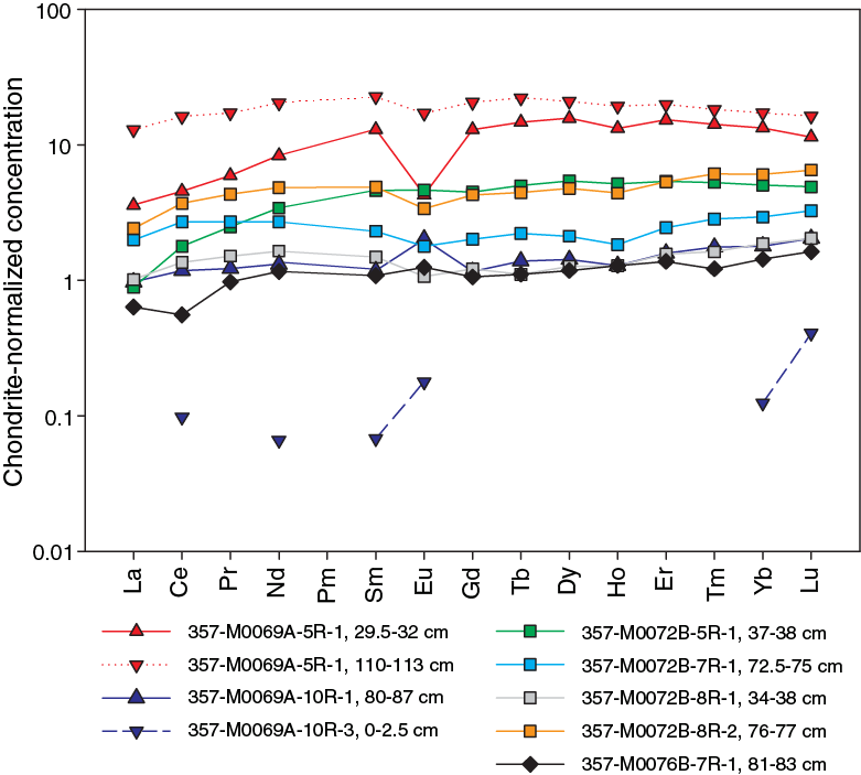
Figure F23. Chondrite-normalized REE plot, Holes M0069A and M0072B.
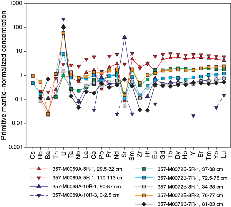
Figure F24. Primitive mantle–normalized extended trace element plot, Sites M0069, M0072, and M0076.
Site M0072
Site M0072 was drilled into the northern portion of the carbonate cap above the Lost City hydrothermal field. Whole-rock major element concentrations range widely in the four samples analyzed from Hole M0072B. SiO2 compositions vary from 38.6 to 50.6 wt% and reflect varying degrees of metasomatic talc-amphibole-chlorite overprinting (impregnated) serpentinized harzburgites. Similar variations were observed in other major oxide concentrations: Al2O3 varies from 0.03 to 0.14 wt%, TiO2 from 0.03 to 0.14 wt%, Fe2O3 from 3.4 to 9.9 wt%, MnO from 0.06 to 0.13 wt%, MgO from 26.1 to 37.6 wt%, CaO from 0.45 to 7.66 wt%, and Na2O from 0.09 to 0.35 wt% (see Figure F22 and Table T4, both in the Eastern sites chapter [Früh-Green et al., 2017a]). No samples contained measurable K2O, and P2O5 is low, ranging from 0 to 0.02 wt%. These samples lie in a relatively narrow Mg# range from 76 to 87, differing only slightly from the average of serpentinized harzburgite samples. Trace element systematics between these samples are very similar, with slight differences in overall enrichment and in particular enrichment in U (Figure F24). REE-normalized patterns are generally flat and vary between 1 to 5 times chondrite (Figure F23). On extended trace element diagrams, Site M0072 samples tend to have positive U and negative Nb anomalies (Figure F24).
The sample with the highest SiO2 (50.6 wt%), TiO2, Al2O3, and CaO and the lowest Fe2O3 and MgO is a talc-amphibolite-chlorite schist (Sample 5R-1, 37–38 cm) that has lower concentrations of lithophile elements (and also shows greater LREE depletion) than the three other Site M0072 samples but also displays a strong positive U anomaly (Figure F24) and exhibits generally very similar trace element systematics to the (impregnated) serpentinized harzburgites. Only Sample 8R-1, 76–77 cm (with lower Fe2O3 and higher CaO than the other Site M0072 serpentinized peridotites), lacks this characteristic enrichment in U. Ni ranges from 1252 to 3687 ppm at this site (see Figure F19 in the Eastern sites chapter [Früh-Green et al., 2017a]).
Site M0076
Site M0076 is the closest site to the Lost City hydrothermal vent field. One sample of serpentinized harzburgite (Sample 357-M0086A-7R-10, 81–83 cm) was analyzed for major and trace element composition. The Mg# of 80 for this sample is one of the highest of the shipboard suite of samples (see Table T4 in the Eastern sites chapter [Früh-Green et al., 2017a]). Like most serpentinite samples, the sample contains elevated Ni and Cr (2810 and 2420 ppm, respectively). It has small positive Pb and Sr anomalies, is enriched in Ba, and has a very strong positive U anomaly. It also has relatively low high field strength element (HFSE) abundances (Zr = 0.38 ppm; Hf = 0.1 ppm) and a very flat chondrite-normalized REE pattern with a small negative Ce anomaly (Figure F23).
Fluid chemistry
Inorganic and organic fluid chemistry
Cations and anions
As reported in detail in Fluid chemistry in the Eastern sites chapter (Früh-Green et al., 2017a), salinities, major elements, trace elements, and anions measured in fluid samples during the expedition had concentrations comparable to bottom seawater (see Tables T6, T7, T8, and T9 in the Eastern sites chapter [Früh-Green et al., 2017a]). There was no detectable sulfide or ammonia (see Tables T6 and T10 in the Eastern sites chapter [Früh-Green et al., 2017a]).
pH, alkalinity, and dissolved inorganic carbon stable carbon isotopic composition
As reported in detail in Fluid chemistry in the Eastern sites chapter (Früh-Green et al., 2017a), the alkalinities and pH of fluid samples were similar to background seawater at all sites (see Table T11 in the Eastern sites chapter [Früh-Green et al., 2017a]), with the exception of pore water from carbonate sands from one of the central site locations (see Figure F25 in the Eastern sites chapter [Früh-Green et al., 2017a]).
Volatile chemistry
As reported in detail in Fluid chemistry in the Eastern sites chapter (Früh-Green et al., 2017a), methane concentrations ranged from below detection limit to 48 µM, and hydrogen concentrations varied from trace levels to 323 µM (see Table T12 in the Eastern sites chapter [Früh-Green et al., 2017a]). Hot spots of hydrogen were observed over Sites M0068–M0072, and hot spots of methane were observed over Sites M0070–M0072 (see Figure F26 in the Eastern sites chapter [Früh-Green et al., 2017a]).
Microbiology
Samples collected
Following the procedure described in detail in Microbiology in the Expedition 357 methods chapter (Früh-Green et al., 2017b), whole-round core (WRC) samples were transferred to the cold room after they were photographed.
At Site M0069, five WRC samples (Sections 357-M0069A-4R-1, 5R-1, 7R-1, 9R-2, and 10R-1) were collected for microbiological studies (Table T3; see MBIOWRC in Supplementary material). These samples were divided into five unflamed frozen samples, three flamed frozen samples, four enrichment samples, two exterior perfluormethylcyclohexane (PFC) samples, two interior PFC samples, three exterior cell count samples, two interior cell count samples, and two single-cell analysis samples. Additional exterior cell count samples were taken at the top and bottom of Section 2R-1 and at the top of and adjacent to the microbiology whole-round sample from Section 5R-1.
Table T3. Whole-round cores collected for microbiological analysis, Sites M0069, M0072, and M0076. Download table in .csv format.
At Site M0072, seven WRC samples were collected for microbiological studies: two from Hole M0072A (Sections 1R-1 and 2R-1) and five from Hole M0072B (Sections 1R-1, 3R-1, 5R-1, 7R-1, and 8R-3) (Table T3; see MBIOWRC in Supplementary material). These samples were divided into seven unflamed frozen samples, five flamed frozen samples, five enrichment samples, six exterior PFC samples, four interior PFC samples, six gas analysis samples, five exterior cell count samples, four interior cell count samples, and four single-cell genomics analysis samples.
At Site M0076, five WRC samples (Sections 357-M0076B-3R-1, 5R-1, 7R-1, 9R-1, and 10R-1) were collected for microbiological studies (Table T3; see MBIOWRC in Supplementary material). These samples were divided into five unflamed frozen samples, four flamed frozen samples, four enrichment samples, seven exterior PFC samples, four interior PFC samples, four gas analyses samples, four exterior cell count samples, four interior cell count samples, and four single-cell analysis samples. Additional exterior cell count samples were taken at the top of Sections 3R-1, 5R-1, 7R-1, and 9R-1 and adjacent to microbiology whole-round samples from Sections 3R-1 and 5R-1.
Samples sent to Kochi Core Center (Japan) were immediately frozen at –80°C and then shipped under temperature-controlled conditions with constant temperature logging. There, WRC exteriors were cut away with a band saw system equipped in a clean booth and used for PFC tracer check (exterior), concentration and isotopic composition of TIC/TOC, vein analysis, in situ organic carbon and Fe mineral analysis, and trapped-gas analysis. The interior portions of the frozen samples were subjected to shore-based nucleic acid analyses and interior PFC, organic, and lipid analyses.
Liner fluid from the core barrels was collected from many cores from each site and was split for PFC, cell count, and organic acid analyses (Table T4).
Table T4. Core liner fluid samples for microbiological analyses, Sites M0069, M0072, and M0076. Download table in .csv format.
Contamination assessment with PFC tracer
Samples of liner fluid, sensor package Niskin bottles, and exterior and interior pieces of WRCs were collected to assess contamination by quantifying the concentration of PFC tracer added during drilling operations (see Microbiology in the Expedition 357 methods chapter [Früh-Green et al., 2017b]). Laboratory atmosphere blanks are also reported in Table T15 in the Eastern sites chapter [Früh-Green et al., 2017a] to define lower detection limits; these values varied throughout the expedition because of buildup of volatilized tracer in the shipboard laboratory. PFC concentrations for samples are reported in picograms PFC per cubic centimeter of sample, and laboratory blanks are reported as picograms PFC per milliliter air.
PFC delivery during drilling operations in all central site holes (M0069A, M0072A, M0072B, M0076A, and M0076B) was weak based on very low concentrations (<100 pg PFC/mL of sample) of tracer in the sensor package and liner fluid samples (see Table T15 in the Eastern sites chapter [Früh-Green et al., 2017a]). Exterior and interior WRC samples had comparably low levels of tracer.
Cell abundance determination
Cell abundance was determined shipboard by direct counting with an epifluorescence microscope (see Microbiology in the Expedition 357 methods chapter [Früh-Green et al., 2017b]). For shipboard analysis of select rock samples, flame-sterilized interior cell count samples were crushed into millimeter-sized grains, and then 3 cm3 was taken for fixation. Minimum quantification limits of the cell counting methods were determined by analysis of procedural negative controls and determined to be 48 cells/cm3.
In select samples from central Sites M0069 and M0072, cell abundance was very low, except in shallow (<1 mbsf) samples (Table T5). In the uppermost sediment sample of Hole M0069A (0.3 mbsf), cell density was ≈1 × 10⁵ cells/cm3. In the uppermost sample of Hole M0072A (0.3 mbsf), cell density was ≈1.1 × 10⁶ cells/cm3. Cell abundance was relatively high (7.3 × 10³ cells/cm3) for rock samples from 0.3 mbsf in this hole. At both sites, cell abundance decreased rapidly with depth. Below 7.0 mbsf in Hole M0069A, cell abundance did not exceed 4 × 10² cells/cm3. In Hole M0072B, cell abundance was around the limit of detection of 102 cells/cm3 below 0.5 mbsf. Cell abundance was not determined shipboard for Site M0076 samples because of time limitations; these samples will be measured in a shore-based laboratory.
Table T5. Microbial cell abundance counted on flame-sterilized interior piece of rock samples, Sites M0069 and M0072. Download table in .csv format.
Enrichment and incubation experiments
The growth and activity of microbial communities was studied in rock samples obtained during the expedition using a variety of culture-based approaches. Flame-sterilized pieces of rock material were ground to fine particles under anoxic conditions and distributed into the various incubation vessels (Table T3; see Microbiology in the Expedition 357 methods chapter [Früh-Green et al., 2017b]).
Samples were used in the following ways:
- To study the assimilation of stable isotope–labeled carbon and nitrogen compounds (Sections 357-M0069A-4R-1 and 5R-1, 357-M0072B-5R-1, and 357-M0076B-9R-1);
- To study the growth of microorganisms at elevated hydrostatic pressures (Sections 357-M0069A-4R-1 and 9R-2, 357-M0072B-7R-1, and 357-M0076B-3R-1);
- To evaluate the presence of hydrogenotrophic and/or methanogenic microorganisms, as well as heterotrophic microorganisms, under alkaline, anoxic conditions (Sections 357-M0069A-4R-1 and 9R-2, 357-M0072B-7R-1, and 357-M0076B-3R-1);
- To study the growth of microorganisms under sulfate-reducing conditions (Sections 357-M0069A-4R-1 and 9R-2, 357-M0072B-1R-1 and 7R-1, and M0076B-7R-1 and 3R-1); and
- To study the activities of microorganisms and extracellular enzymes (Sections 357-M0072B-3R-1 and M0076B-5R-1).
Water samples for microbiological analysis
Water from sensor package Niskin bottles and CTD rosette Niskin bottles was sampled for measurements of PFC, cell counts, and nucleic acids from Sites M0069, M0072, and M0076 (Tables T6, T7) and for many chemical measurements (see Water sampling and sensor package data in the Expedition 357 methods chapter [Früh-Green et al., 2017b]). Water samples from the CTD rosette were also obtained from two locations near Site M0072: Hole M0072X (over the Atlantis Fracture Zone) and Hole M0072Z (near Marker H of the Lost City hydrothermal field). Select water samples were used to quantify cell abundance in fluid samples (Table T8). Cell abundance had little variation with depth, ranging from 3.2 × 10⁴ cells/mL (sampled at 11.3 mbsl) to 7.8 × 10⁴ cells/mL (sampled at 293.3 mbsl).
Table T6. Water samples collected from sensor package Niskin bottles for microbiological analysis, Sites M0069, M0072, and M0076. Download table in .csv format.
Table T7. Water samples collected from CTD Rosette Niskin bottles for microbiological analyses, Sites M0069 and M0072. Download table in .csv format.
Table T8. Microbial cell abundance counted on water samples, Site M0069. Download table in .csv format.
Sensor package data
Mapping drill data onto the sensor plots for all sites was done graphically, and for records of approximately 1000 min, the potential errors are on the order of ±5 min.
Hole M0069A
The sensors started recording in Hole M0069A at 2107 h (UTC – 2 h) on 6 November 2015, and data are recorded in two files (Figure F25; Table T9). Overall, Hole M0069A exhibited no CH4 anomalies with a background maximum of 0.4 nM. Background values for pH were 8.8, and pH generally increased with depth, with steeper increases during drilling of the upper six cores. Water temperature varied from 9.10°C to 9.95°C, with no clear trends in variation associated with drilling conditions.

Figure F25. Sensor data, Hole M0069A.
Table T9. Sensor signal time log, Hole M0069A. Download table in .csv format.
Oxidation-reduction potential (ORP) signals during drilling were variable (Figure F25A). The ORP signal started dropping prior to the beginning of Core 1R, implying that fluids more reducing than seawater were emanating from this site. This first ORP excursion had two minima at 2216 and 2251 h. The first minimum occurred at about the time Core 1R was finished (penetration depth = 1720 mm), and the second happened during the switch from Core 1R to Core 2R. This excursion toward lower ORP values did not return to near-background values of about 340 mV until 0231 h, after the end of Core 2R at 3440 mm, at which time another ORP minimum started. Drilling of Core 2R stopped at 2346 h to add a new drill rod and restarted at 0013 h; however, the ORP signal does not seem to have been impacted in a significant way during this period.
The next major ORP minimum started at 0231 h between Cores 2R and 3R when the flush pump was not connected to the drill string. It reached a minimum at 0323 h, just prior to the beginning of Core 3R, and returned to background values at 0450 h. The implication is that the ORP signal reached a minimum during the period of nonflushing and was then diluted by the restart of flushing, resulting in the signal returning to near–bottom water values. Unfortunately, a gap in the RD2 drill data from 0414 to 0634 h means we are unable to definitively tie drilling activities to this ORP minimum or the next minimum at 0525 h. This latter minimum, however, occurred entirely during the period between the end of Core 3R (5160 mm) and the start of Core 4R when most likely the hole was not being flushed and formation fluid was seeping out of the hole with less dilution from bottom seawater.
The next ORP minimum started at 0640 h, was lowest at 0646 h just prior to the beginning of Core 4R, and approached background values at 0840 h, just after the start of Core 5R (6880 mm) when a new minimum began. This minimum lasted about 2.5 h and occurred entirely within the time of drilling Core 5R. At 0938 h, drilling was stopped to add a drill rod. Drilling recommenced at 0950 h, corresponding to the minimum ORP value. The ORP value steadily declined throughout the remaining time that Core 5R was being drilled, ending at 8600 mm.
The second sensor data file (Figure F25B) for this hole shows that two different mechanisms can result in ORP minima. Drilling of Core 8R started at 1759 h (11,320 mm). The first major ORP minimum started at 1743 h, reached a minimum at 1840 h, and rebounded to near-background values entirely within Core 8R. This particular core was straight drilling the entire time with no stops for adding a new drill rod; therefore, the hole was being flushed with bottom water the entire time. The flush rate started at 15 L/min, increased to 20 L/min at 1818 h, and increased again at 1849 h to 20 L/min, where it stayed for the remainder of the core, which ended at 1921 h (13,040 mm). Thus, this negative ORP excursion was the result of penetration into a more reducing horizon within the hole. Although variable flush rates might have influenced the shape of the peak, the strong negative excursion does not correlate with periods of flushing or no flushing, which appears to be the case with the next ORP minimum. The next ORP minimum started at 0017 h and was lowest at 0100 h, almost entirely within Core 10R, which started at 2322 h (14,720 mm). In this case, however, drilling stopped at 0010 h (15,234 mm) to add a drill rod and started again at 0102 h. Decreasing ORP values occurred during a period with no flushing, and once flushing resumed, ORP values immediately started to increase. In this case, it seems the lack of flushing produced the ORP excursion by allowing the more reducing formation fluids to be pumped past the sensors, and then the signal was diluted when flushing resumed. Core 10R ended at 0249 h (16,440 mm). It seems likely this same mechanism produced the ORP minimum centered at 0448 h, although a data gap between 0250 and 0440 h makes this conjecture less reliable than others. This excursion took place during the period when Core 11R was unsuccessfully attempted. The beginning of the excursion likely started during a period of no flushing because the drill never proceeded beyond 16,440 mm where Core 10R ended, so no new reducing horizons were encountered. Drilling of Core 11R started at 0440 h with a flush rate of 20 L/min that was maintained until drilling ceased at 0530 h. Flushing continued at 20 L/min until 0545 h when it was increased to 50 L/min for 5 min. Again, this anomaly appears to have started during a period of no flushing and was diluted away by flushing the hole. There are no drill data for the last ORP minimum at 0612 h.
Hole M0072A
Hole M0072A is a short two-core hole with no CH4 anomalies and only two negative ORP excursions (Figure F26; Table T10). CH4 steadily increased from about 0.2 nM at the start of drilling until the end of Core 1R, where it stabilized at 1.5 nM for the duration of drilling. The pH values increased downhole from 7.8 to 7.9. The first ORP excursion started at 1238 h, 1475 mm into Core 1R. The ORP minimum was at 1247 h (1627 mm), about 4 min before the completion of Core 1R (penetration depth = 1720 mm). The drill started turning at 1332 h and stopped at 1339 h. It is uncertain what occurred during this time, as the drill logs indicate that Core 2R started at 1418 h. The second ORP excursion started at 1339 h, reached a minimum at 1349 h prior to the start of Core 2R, and returned to background values at 1438 h at the end of Core 2R (2225 mm). There are no drill data from 1335 to 1414 h, so we can only speculate that this ORP minimum is the result of a lack of flushing while core barrels were being changed.
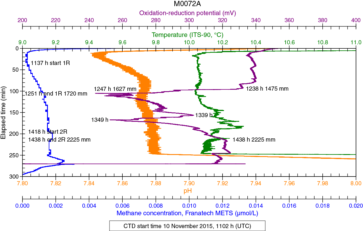
Figure F26. Sensor data, Hole M0072A.
Table T10. Sensor signal time log, Hole M0072A. Download table in .csv format.
Hole M0072B
The sensors started recording in Hole M0072B at 1652 h on 10 November 2015 (Table T11), with the data plotted in three files. In the first 300 min of sensor data (Figure F27A), CH4 background values ranged from 0.2 to 1.0 nM and there was a small CH4 peak (1.5 nM) centered at 1744 h (1461 mm) while drilling Core 1R. The most significant event during this period was the 11 nM CH4 signal centered at 2025 h while drilling Core 2R. This CH4 increase was accompanied by a negative excursion in ORP, which is indicative of more reducing fluids being flushed from the hole. The pH value gradually increased throughout this period, suggesting that formation fluids were being influenced by serpentinization.
Table T11. Sensor signal time log, Hole M0072B. Download table in .csv format.
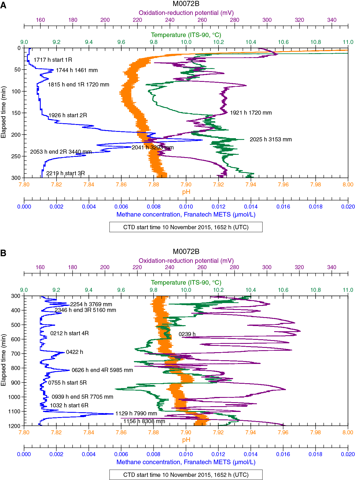
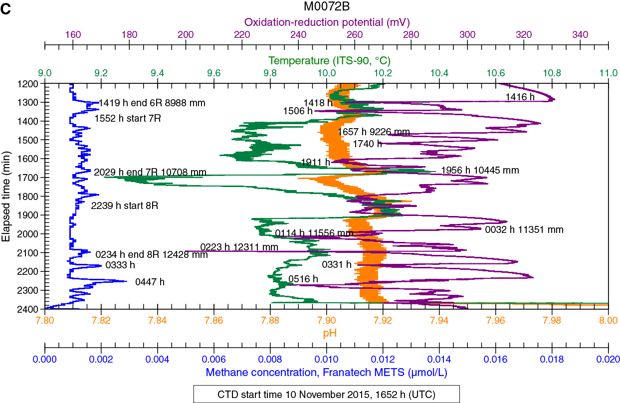
Figure F27. Sensor data, Hole M0072B.
In the next 900 min of the sensor data (Figure F27B), CH4 background values were near 1 nM and there were several small CH4 peaks, all accompanied by negative ORP signals. The small CH4 peak at 2254 h occurred prior to stopping drilling during Core 3R to add a drill rod and thus was not induced by this process. While drilling Core 4, the core barrel became stuck in the BHA, which necessitated that a new BHA be deployed. Additionally, the hole was reamed to 5160 mm and then open-hole drilled to 5985 mm. The CH4 peak at 0422 h occurred during this process, and the CH4 peak at 0626 h happened at the end of this process, when the hole would not have been flushed. There were also several ORP minima associated with Core 4R operations. The largest of the CH4 peaks (5.5 nM) occurred at 1129 h while drilling Core 6R (7990 mm) just after a new drill rod was added between 1103 and 1113 h. The pH value continued to slowly increase downhole during this period and exhibited a significant increase associated with the 1119 h CH4 peak. This peak was followed by the lowest ORP voltage (210 mV) seen during this period.
The final 1200 min of drilling at this hole (Figure F27C) produced a few small CH4 signals and numerous sharp variations in ORP. The ORP minimum at 1657 h occurred while Core 7R was being drilled, and the one at 1740 h was coincident with stopping of drilling to add a new drill rod at 9705 mm. The next ORP minimum at 1911 h (10,362 mm) also occurred while drilling Core 7R with relatively uniform rotation speed and seawater flush rate. Drilling Core 8R stopped at 0050 h to add a drill rod and resumed at 0112 h; therefore the ORP excursion that started at 0032 h and reached a minimum at 0114 h began during a period when the hole was not being flushed and ended as drilling and flushing resumed. The ORP minimum at 0223 h happened during normal drilling a few minutes prior to completion of Core 8R. The small CH4 peaks at 0333 and 0447 h and the ORP minima at 0331 and 0516 h all happened during the attempt to start Core 9R, which had to be abandoned because of loss of communication with the drill.
Hole M0076A
Hole M0076A is a shallow, one-core hole with two very small ORP minima (Figure F28; Table T12), although the ORP signal throughout was more negative than many other sites where the background value was near 340 mV. The first small minimum started simultaneously with drilling at 1455 h and peaked at 1516 h, 492 mm within the core. The ORP value then increased slightly to 1650 mm at 1516 h, when it again decreased until the minimum at 1523 h (1720 mm) when drilling ceased. The flush rate was constant at 20 L/min throughout the drilling of this core, so it appears that two separate horizons of more reducing fluid were encountered. There were no CH4 peaks, and background values were 0.5 to 0.7 nM. After a hydraulic leak was discovered, drilling ceased, and the drill lifted off the bottom at 1537 h.
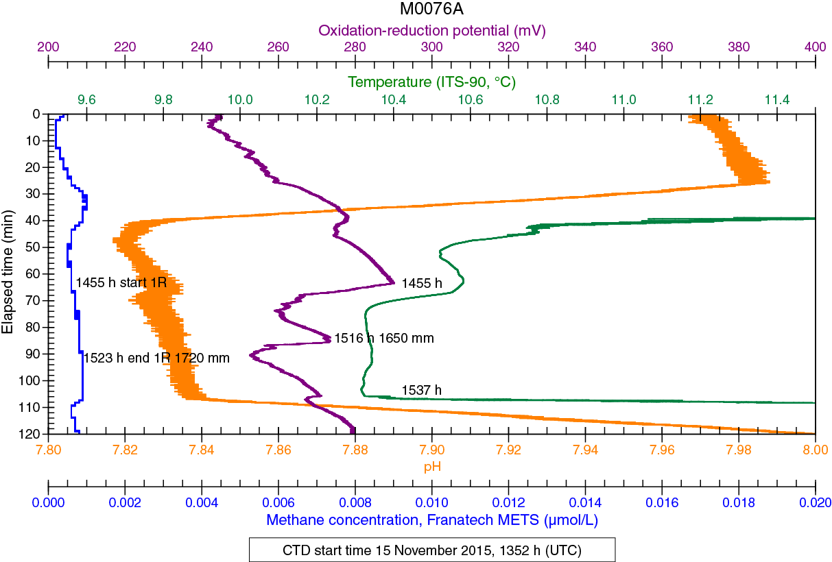
Figure F28. Sensor data, Hole M0076A.
Table T12. Sensor signal time log, Hole M0076A. Download table in .csv format.
Hole M0076B
The sensors started recording in Hole M0076B at 1739 h on 15 November 2015. Data for this hole are broken into three separate sections as a result of the need to recycle power to the RD2 drill that necessitated a restart of the CTD software each time (Figure F29). All the times and bit depths for relevant events are listed in Table T13.

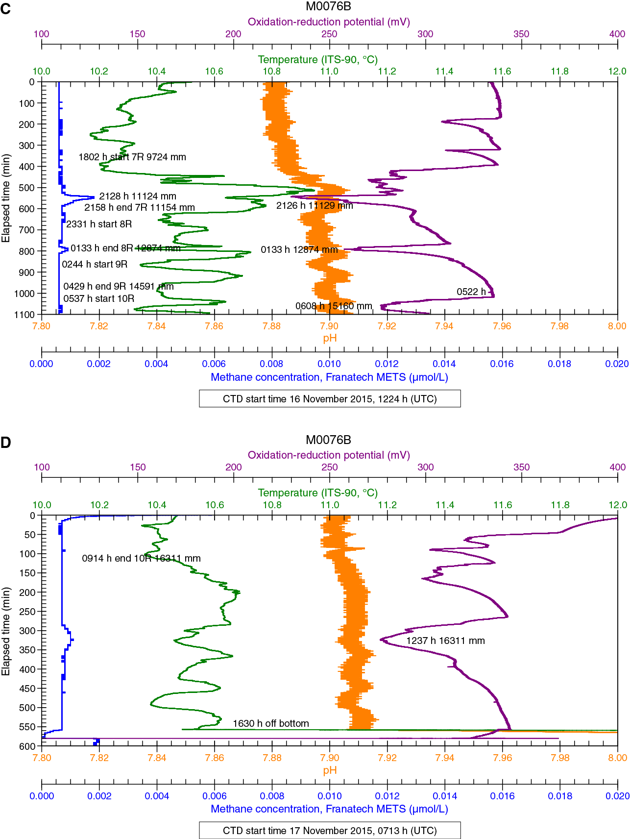
Figure F29. Sensor data, Hole M0076B.
Table T13. Sensor signal time log, Hole M0076B. Download table in .csv format.
The touchdown of the drill at 1926 h resulted in a small but significant jump in pH from 7.84 to 7.86, indicating that the sediments likely had a slightly higher pH than bottom seawater (Figure F29A, F29B). The CH4 background value was about 0.5 nM, and an increase in CH4 concentration began at about 2009 h, almost 30 min before drilling began, indicating that landing the drill likely displaced a shallow CH4 reservoir. The CH4 concentration reached a maximum value of 13.2 nM at 2100 h (1119 mm) about 13 min after drilling commenced for Core 1R. The CH4 peak reached background concentration at the start of Core 2R about 2 h and 20 min after it was started. This CH4 peak coincided with a significant drop in ORP, indicating that fluids more reducing than seawater were being flushed from the hole. A slight increase in temperature was also coincident with the CH4 and ORP excursions. After the initial disturbance centered at 2100 h, the next several hours of drilling were relatively uneventful with the exception of the event at 0446 h (Figure F29B), which included a negative ORP excursion, a temperature decrease, and a very small (1.3 nM) CH4 peak. This event took place well after the addition of a drill rod (0318–0339 h; 3934 mm) during the Core 3R run. Other than this small peak, CH4 concentrations remained around 0.5 nM.
From 1224 h on 16 November to 0639 h on 17 November, there was relatively little variation in sensor signals (Figure F29C). The most significant events were an ORP minimum at 2126 h and a small CH4 peak at 2128 h (1.7 nM) on November 16. The time difference between the ORP minimum and the CH4 peak is likely related to the time delay associated with diffusion across the METS membrane (see Water sampling and sensor package data in the Expedition 357 methods chapter [Früh-Green et al., 2017b]). The completion of Core 8R at 0133 h on November 17 corresponded with a coincident drop in ORP and a small CH4 maximum. The ORP excursion that reached a minimum at 0608 h while drilling Core 10R started after completion of Core 9R and well before Core 10R was started.
Cycling of the power on the RD2 drill caused a 31 min interruption in data after Core 10R started (Table T13), and it appears that a transient in methane concentration and ORP signal occurred during this period, as seen in the drop in methane concentration and ORP signal at the start of the third period of data (Figure F29D). At the end of the previous data set, methane concentration was 0.6 nM, whereas methane concentrations began at 5.9 nM (data taken from CTD file) at the start of the final data set. A drill rod was added while drilling Core 10R between 0631 and 0706 h at a depth of 15,239 mm. This new CTD file opened at 0713 h with the drill bit at 15,330 mm. After this excursion, CH4 remained about 0.6 nM for the rest of the deployment. The only other interesting feature during this period is the ORP excursion centered at 1237 h during attempts to drill an additional core. Coring ended with Core 10R at 0914 h (16,311 mm).
Borehole plugs
One successful attempt was made after RD2 drilling operations to install a borehole plug in Hole M0072B. For further details on borehole plugs, see Borehole plugs in the Expedition 357 methods chapter (Früh-Green et al., 2017b).
After tripping out the drill string in Hole M0072B, a three-unit borehole plug system was inserted into the open hole (Figure F30). The borehole plug consisted of a 2.17 m length of titanium tube with a ball-valve assembly at the upper end, an additional titanium rod in the center, and a packer element below. The entire length of the assembly was 5.12 m, with a stop ring on the upper titanium pipe set 1.02 m from the top of the assembly. Penetration reached 12.43 mbsf. The system penetrated to the target depth of 4.1 mbsf with the packer element set below 3.0 mbsf. The liftoff of the drill rig from the system stick up went well, and the top of the plug system likely sits about 1.02 m above the seafloor.

Figure F30. Borehole plug emplacement, Hole M0072B.
Because of difficult drilling conditions, coring equipment was left in two other central holes. In Hole M0069A, difficulty with handling operations resulted in the loss of the entire BHA and drill string in the hole. The entire string of eight drill rods plus the BHA totaled 16.8 m. This string was left behind in a 16.44 m hole, so it is possible that 0.44 m of pipe sticks out from the seafloor at this location (Figure F31). Similarly, difficult drilling conditions resulted in the loss of seven drill rods and a BHA in Hole M0076B. This 15 m length of equipment is likely beyond reach in the 16.3 m borehole (Figure F32).

Figure F31. Equipment left behind in borehole, Hole M0069A.
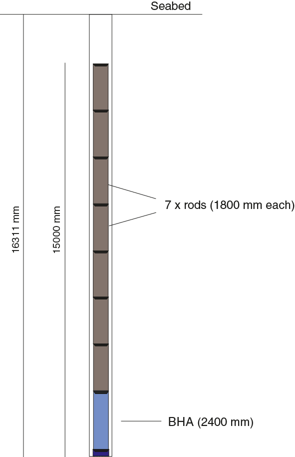
Figure F32. Equipment left behind in borehole, Hole M0076B.
Physical properties
Site M0076
At Site M0076, two holes were cored with a total recovery of ≈12 m. The deeper hole (M0076B), which was cored to a total depth of 16.3 mbsf, had significantly better recovery (71%) than the shallower Hole M0076A (1.72 mbsf; ≈23% recovery). Physical properties measurements were acquired from all cores, including measurements on four samples from Hole M0076B.
Density and porosity
Gamma density (GD) for Hole M0076A varies between 1.43 and 2.52 g/cm3 and has a mean of 2.00 g/cm3 (Figure F33). Hole M0076B cores have gamma densities with a similar range but slightly higher values between 1.74 and 2.83 g/cm3 and a mean density of 2.34 g/cm3 (Figure F34). The overall mean density for this site is 2.34 g/cm3 (Table T14). This range is likely indicative of the fractured nature of the rock in this hole, with lower densities a function of poor core quality associated with more fragmented intervals. Density does not vary significantly with depth.
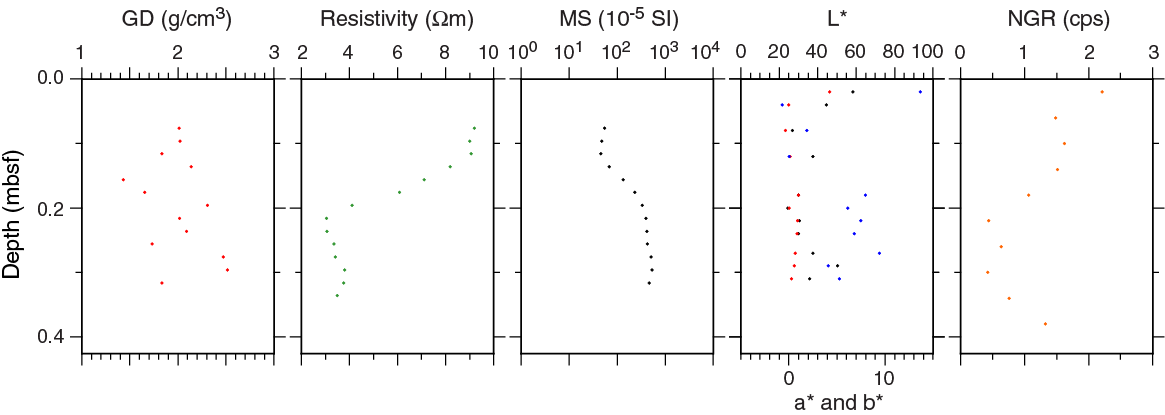
Figure F33. Physical properties, Hole M0076A.

Figure F34. Physical properties, Hole M0076B.
Table T14. Physical properties, Sites M0076, M0069, and M0072. Download table in .csv format.
Four different serpentinite samples were taken from Hole M0076B for moisture and density (MAD) and triaxial P-wave velocity measurements (see below) at 5.96, 7.38, 9.19, and 11.60 mbsf (Figure F34; Table T15). These samples include two serpentinized harzburgites, one serpentinized dunite, and one serpentinized peridotite. Their average grain density is 2.60 ± 0.03 g/cm3. Their porosity varies more significantly between 3.1% and 8.9%. No Hole M0076A samples were analyzed.
Table T15. Grain density, porosity, and P-wave velocity for discrete samples, Sites M0076, M0069, and M0072. Download table in .csv format.
Bulk densities from MAD analyses are comparable to the corresponding gamma density measurement (Figure F34). Preferential sampling in more coherent intervals means that the MAD data set has overall higher mean densities than the whole-core data.
P-wave velocity
Sample 357-M0076B-4R-1, 80.0–82.0 cm, measured under wet conditions, has an x-direction velocity of 5.60 km/s (Figure F34, Table T15). The x-direction is horizontal in real space. The second horizontal direction, the y-direction, has a higher P-wave velocity (6.35 km/s). P-wave velocity measured along the z-direction (vertical) is 6.29 km/s. Mean P-wave velocity for this sample is 6.08 km/s. Sample 5R-1, 65.0–67.0 cm, also measured under wet conditions, has an x-direction velocity of 4.12 km/s. The y-direction for this sample has a higher P-wave velocity (4.63 km/s). P-wave velocity measured along the z-direction is 4.64 km/s. Mean P-wave velocity for this sample is 4.46 km/s. Sample 6R-1, 121.0–123.5 cm, was measured twice under dry conditions, resulting in x-direction velocities of 4.96 and 5.72 km/s, one y-direction velocity of 6.10 km/s, and vertical z-direction velocities of 6.46 and 6.05 km/s. The mean of all measurements is 5.86 km/s. Sample 8R-1, 44.5–47.0 cm, could only be measured in the x- (4.20 km/s) and z-directions (5.99 km/s) because the sample showed numerous fissures parallel to the y-direction. The mean P-wave velocity for this sample is 5.09 km/s.
Electrical resistivity
Electrical resistivity in Hole M0076A varies from 3.1 to 9.2 Ωm (Figure F33); the range in resistivity is greater in Hole M0076B (from 0.2 to 17.8 Ωm), and the mean is lower (2.8 Ωm) (Figure F34). Two major peaks in electrical resistivity occur in Hole M0076B at 3.7 and 5.2 mbsf. Both of these resistivity highs coincide with intervals of rubble (see Lithology, alteration, and structure). Data are more likely a function of poor core quality, rather than representative of the resistivity of the samples involved. Deeper in this hole, below 12.2 mbsf, cores have very low electrical resistivity, varying between 0.4 and 1.6 Ωm.
Magnetic susceptibility
In Hole M0076A, magnetic susceptibility (MS) is moderately high and ranges between 45 × 10–5 and 528 × 10–5 SI (Figure F33). In Hole M0076B, magnetic susceptibility is typically high with a mean value of 1283 × 10–5 SI and ranges from 22 × 10–5 to 5477 × 10–5 SI (Figure F34). Overall, magnetic susceptibility increases with depth. In both holes, magnetic susceptibility is anticorrelated with electrical resistivity.
Natural gamma radiation
Natural gamma radiation (NGR) measurements on Site M0076 cores are consistently very low, a reflection of the lithologies encountered (Figures F33, F34). There is no net change in NGR with depth, although there is clearly variability along the profile. In Hole M0076B, NGR increases overall to a maximum at ≈6.5 mbsf and decreases again with depth (Figure F34). Other maxima are noted at ≈5.1, 5.6, 7.1, 8.0, 11.1, and 12.0 mbsf. Because of the uncalibrated nature of the NGR counts per second, absolute values are not presented here.
Color reflectance
Color reflectance measurements were taken on all Site M0076 cores (Figures F33, F34; Table T14). Lightness (L*) in Hole M0076A varies from 24.45% to 58.26% with a mean value of 36.88%. a* and b* mean values are 0.75 and 5.64, respectively. a* values are relatively constant, ranging from –0.36 to 4.25, but b* values are highly scattered (between –0.71 and 13.69). L* in Hole M0076B varies between 19.37% and 58.85% with a mean value of 36.30%, which is comparable to that of the shallower Hole M0076A. a* is less variable than other color reflectance parameters, varying between –6.45 and 2.29 with a mean of –0.66. b* varies from –2.26 to 14.05 and has a mean of 2.17.
Site M0069
One hole was cored at Site M0069. Hole M0069A is the deepest hole (≈16.4 m) and the hole with the highest recovery (75%) across all sites drilled during Expedition 357.
Density and porosity
In Hole M0069A, gamma density ranges from 1.49 to 2.76 g/cm3 (Table T14; Figure F35), corresponding to the density of water-saturated sediments and altered mafic/ultramafic rocks, respectively. The mean gamma density is 2.29 g/cm3. A clear change in density occurs at 6.9 mbsf, coincident with the boundary between these two units. Above 6.9 mbsf, density varies between 1.65 and 2.00 g/cm3 and overall exhibits less scatter than is found deeper in the hole. Below 6.9 mbsf, gamma density varies between 1.49 and 2.75 g/cm3, with high variability observed over short distances. This variability is the effect of drilling-induced fractures, which are observed especially at the top of individual cores.
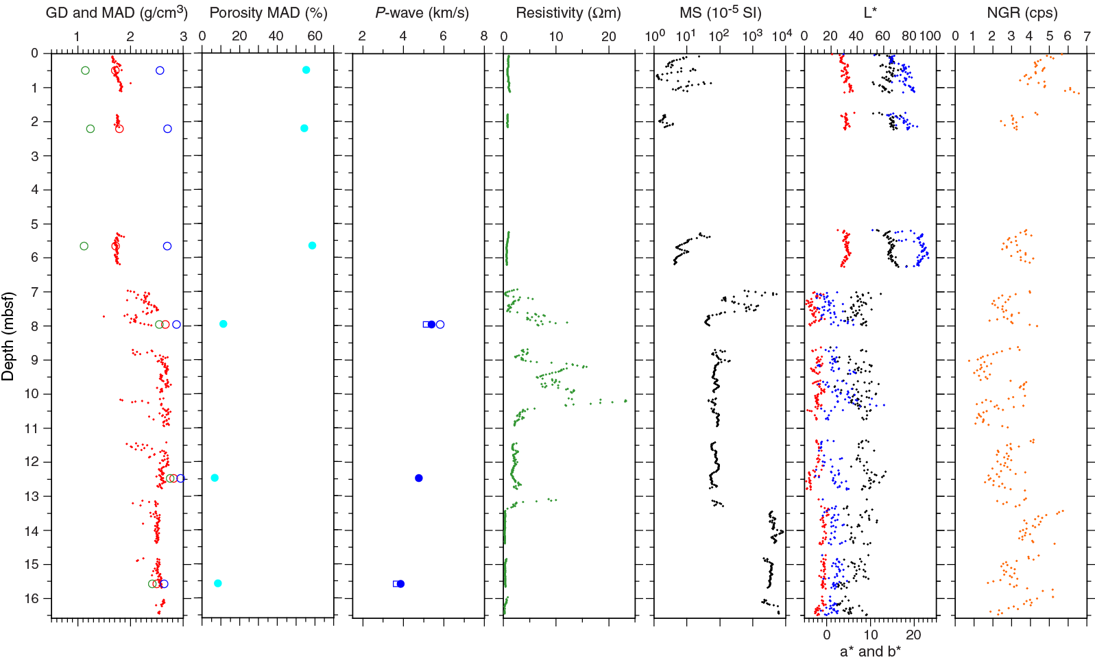
Figure F35. Physical properties, Hole M0069A.
Density and porosity were calculated for Site M0069 discrete samples (Figure F35; Table T15). Three sediment samples were taken at 0.49, 2.21, and 5.65 mbsf in the upper portion of Hole M0069A (above 6.9 mbsf). Their grain density is 2.65 ± 0.08 g/cm3, and their porosity is 56.1% ± 2.2%. There are no systematic changes in these parameters with depth. The spread in the three density parameters (grain, bulk, and dry) is significant compared to measurements on the rock minicores. This is to be expected because of the much larger sediment porosities. The metadolerite sample from 7.95 mbsf has a grain density of 2.87 g/cm3 and a porosity of 11.4%. The grain density and porosity of the talc-amphibole-chlorite schist sample (12.47 mbsf) are 2.95 g/cm3 and 6.8%, respectively, and those of the serpentinized harzburgite sample (15.57 mbsf) are 2.64 g/cm3 and 8.5%, respectively. The schist and metadolerite samples have higher bulk density than the equivalent gamma density measurement. These higher values are a function of preferential sampling of more coherent material for the discrete measurements.
P-wave velocity
Three discrete hard rock samples were obtained from Site M0069 cores (Figure F35; Table T15). The metadolerite sample (357-M0069A-5R-1, 107.0–109.0 cm) has an x-direction (horizontal) P-wave velocity of 5.81 km/s. The y-direction (horizontal) has a lower P-wave velocity (5.39 km/s). P-wave velocity measured along the z-direction (vertical) is 5.11 km/s. The mean P-wave velocity for metadolerite is 5.44 km/s. P-wave velocity of talc-amphibole-chlorite schist (Sample 8R-1, 114.5–117.0 cm) could only be reliably measured in the y-direction (horizontal): 4.75 km/s. The serpentinized harzburgite sample (10R-1, 85.0–87.0 cm) permitted reliable measurement in the y- and z-directions with P-wave velocities of 3.86 and 3.65 km/s, respectively, and an average of 3.76 km/s. This value is very low for serpentinized harzburgite, which can be tentatively explained by the multitude of healed hairline cracks in the cylindrical sample.
Electrical resistivity
Electrical resistivity in Hole M0069A is very low, ranging from 0.6 to 1.2 Ωm above 6.9 mbsf (Figure F35; Table T14), and principally reflects the resistivity of the seawater pore water. Resistivity is controlled by the porosity of these cores. This low electrical resistivity, in tandem with the low density, is indicative of water-saturated sediment in the upper part of this hole. Between 7.0 and 13.5 mbsf, resistivity increases with much greater scatter, varying between 0.3 and 23.3 Ωm. Below 13.5 mbsf, electrical resistivity decreases again to around 2 Ωm. This decrease is likely due to highly fractured, water-saturated core in which resistivity is porosity controlled.
Magnetic susceptibility
In Hole M0069A, magnetic susceptibility ranges from 1 × 10⁻⁵ to 8363 × 10–5 SI (mean = 1041 × 10–5) with a trend similar to that of gamma density (Table T14; Figure F35). Electrical resistivity in the sediment interval also seems to follow the trend of magnetic susceptibility. Between 7.0 and 13.5 mbsf, magnetic susceptibility first increases to 5268 × 10–5 SI (7.1 mbsf) and then decreases to a mean of 109 × 10–5 SI between 8.5 and 13.5 mbsf. The deepest part of Hole M0069A (below 13.5 mbsf) exhibits the highest magnetic susceptibility values, between 1952 × 10–5 and 8363 × 10–5 SI, indicating higher contents of magnetic minerals.
Natural gamma radiation
Similar to Site M0076, Site M0069 cores have consistently low NGR with no overall change in intensity with depth (Figure F35). Between ≈5 and 14 mbsf, values are slightly lower on average, and the underlying material and overlying sediments have slightly higher values. There is no clear distinction in this parameter between unconsolidated sediment and basement material, which is expected because the sediments are principally calcareous (see Lithology, alteration, and structure) and the heterogeneous lithologies of the basement have very low natural radioactivity.
Color reflectance
In Hole M0069A, L* varies between 19.50% and 77.43% with a mean value of 49.40% (Table T14; Figure F35). Mean values of a* and b* are 0.35 and 7.91, respectively. There are clear differences between shallow sediment cores (above 6.9 mbsf; above and including Core 5R) and deeper hard rock cores. For shallower cores, a* and b* are both positive, indicating chromaticity in the red and yellow parts of the spectrum, respectively. The deeper basement material is characterized by predominantly negative a* (green) and values of b* close to zero, indicating dominantly greenish gray colors. L* is significantly higher in sediment cores, indicating much lighter core material compared to the darker (lower L*) underlying cores. Scattering of the parameters is more pronounced in the deeper cores. These observations are consistent with the homogeneous sediment structure in the shallower cores and the highly heterogeneous mafic and ultramafic intervals in the deeper part of Hole M0069A.
Site M0072
Two holes were drilled at Site M0072, recovering a total of ≈13.8 m of material. Hole M0072B, the deeper (11.6 mbsf) of the two holes, had higher recovery (52%) than the shallower (2.2 mbsf) Hole M0072A, which had 39% recovery.
Density and porosity
In Hole M0072A, density varies between 1.51 and 2.63 g/cm3 with a mean of 2.01 g/cm3 (Figure F36). This large variation is a consequence of the highly fractured nature of the rocks in this hole. In Hole M0072B, gamma density ranges from 1.61 to 2.77 g/cm3 with a mean of 2.35 g/cm3 (Figure F37). In the uppermost 4 m of this hole, the mean density is 2.13 g/cm3. For the deeper cores, a slight net decrease in density is observed, with a mean value of 2.44 g/cm3. Larger density variations are observed at the tops of cores and are likely a function of drilling-induced fractures. A serpentinized harzburgite sampled from material recovered from Hole M0072B (11.02 mbsf) has a grain density of 2.58 g/cm3 and a porosity of 4.3% (Table T15).
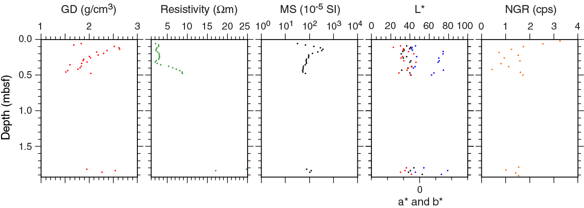
Figure F36. Physical properties, Hole M0072A.
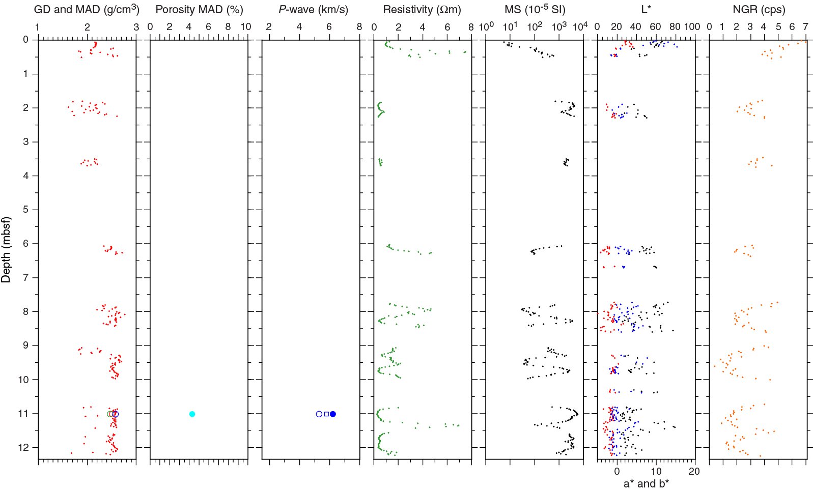
Figure F37. Physical properties, Hole M0072B.
P-wave velocity
One discrete serpentinized harzburgite sample (357-M0072B-8R-1, 31.0–33.0 cm) from Site M0072 was analyzed (Figure F37; Table T15). It has an x-direction (horizontal) P-wave velocity of 5.29 km/s. The second horizontal direction, the y-direction, has a higher P-wave velocity of 6.20 km/s. P-wave velocity measured along the z-direction (vertical) is 5.79 km/s. The mean P-wave velocity for the serpentinite is 5.76 km/s.
Electrical resistivity
Electrical resistivity ranges from 2.0 to 24.8 Ωm in Hole M0072A (mean = 5.4 Ωm) (Figure F36). In Hole M0072B, resistivity does not exhibit two distinct populations with depth as the gamma density does (Figure F37). In general, electrical resistivity is low to moderate (Table T14). In the first core, it reaches the highest values encountered in the hole (7.5 Ωm at ≈0.3 mbsf). Between 2.5 and 5.0 mbsf, resistivity is low with a mean value of 0.5 Ωm. Below 6.0 mbsf, fluctuating high and low electrical resistivity was observed, with values ranging from 0.3 to 6.9 Ωm and a mean of 1.6 Ωm.
Magnetic susceptibility
In Hole M0072A, magnetic susceptibility is low to moderate, from 31 × 10–5 to 360 × 10–5 SI, with a mean of 113 × 10–5 SI (Figure F36). In Hole M0072B, aside from the first core, magnetic susceptibility appears clearly anticorrelated with electrical resistivity (Figure F37). Overall, magnetic susceptibility varies between 6 × 10⁻⁵ and 5814 × 10–5 SI and is high, with the exception of the first core, with a mean value of 1632 × 10–5 SI.
Natural gamma radiation
At Site M0072, NGR is low, similar to the two other sites in the central area (Figures F36, F37; Table T14). The downhole profile observed in Hole M0072B suggests a very subtle net decrease in the intensity of NGR with depth.
Color reflectance
Color reflectance measurements were taken on the split surfaces of the archive halves of all Site M0072 cores. Hole M0072A cores have low L* variation between 31.03% and 52.62% with a mean value of 38.55% (Table T14; Figure F36). a* (mean = –0.87) and b* (mean = 0.53) are close to zero, clearly indicating a gray color, and relatively consistent with depth, ranging from –1.63 to –0.23 (a*) and from –0.51 to 1.75 (b*). In Hole M0072B, L* varies between 23.52% and 79.00%, and the mean value is 44.34% (Table T14; Figure F37). a* ranges from –5.44 to 4.01 (mean = –1.46), and b* ranges from –2.10 to 15.35 (mean = 1.77). It is mostly deeper cores that demonstrate these large variations in the color space dimensions. Above 2.5 mbsf, the scatter in L*, a*, and b* is lower than it is in the deeper part of the hole.
Summary
More than 30 m of core was recovered across the central sites during Expedition 357. Physical properties measurements were taken on all recovered material, including 11 samples utilized for MAD analyses and triaxial P-wave measurements. The central sites are characterized by moderate to high magnetic susceptibilities and excursions in resistivity that are far less common in the other areas studied during Expedition 357. These two parameters are typically anticorrelated, which is particularly evident at Sites M0076 and M0072 (Figures F34, F37). Any systematic relationship between magnetic susceptibility and resistivity is less well defined at Site M0069.
The sediment interval that caps Hole M0069A has distinct physical properties responses, as expected (Figure F33). There is a clear demarcation in all physical properties parameters at the sediment/rock interface at ≈6.9 mbsf. Three principal units in Hole M0069A are defined by physical properties parameters: the calcareous sediment cover (above ≈6.9 mbsf), an interval dominated by metadolerite (≈6.9–13.5 mbsf), and a unit of serpentinized harzburgite with dunitic intervals (≈13.5 mbsf and below) (see Lithology, alteration, and structure). Such units at the other central sites are less easy to define purely on the basis of the petrophysical measurements acquired.
A crossplot of density and porosity from the 11 MAD samples indicates some clear populations in the density-porosity space that can be attributed to lithology. The serpentinized lithologies (referred to as serpentinites in Figure F38) and calcareous sediments have lower densities than metadolerite and schist. The porosity of the sediments is very high compared to that of the hard rock samples.
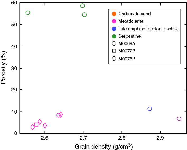
Figure F38. Grain density and porosity data from MAD analyses, Holes M0069A, M0072B, and M0076B.
Downhole logging
A 15 m interval of Hole M0076B was logged through-pipe utilizing the OAG tool (see Downhole logging in the Expedition 357 methods chapter [Früh-Green et al., 2017b]) over a period of 1 h. Because the drill pipe became irrevocably stuck, it was not possible to recover the drill string to the RD2, and therefore open-hole logging operations in this hole were not possible. However, deployment of the OAG tool through the stuck drill string allowed acquisition of a through-pipe total gamma ray measurement.
Operations
Downhole logging operations in Hole M0076B commenced at 1250 h local time on 17 November 2015. Challenging hole conditions resulted in the drill string becoming stuck, and the hole was terminated at 16.31 mbsf. Attempts to free the pipe ceased with a final bit depth for logging of 15.37 mbsf (Figure F39). Instead of open-hole logging operations, the OAG tool was deployed to acquire through-pipe total gamma ray data.

Figure F39. Geometry of logging from the RD2, Hole M0076B.
The OAG tool was retrieved from its magazine and connected to the winch cable with an overshot. The tool was then initialized, data acquisition for the winch depth encoder was started, and the tool was deployed via cable to the bottom of the drill string with the gamma measurement point reaching a maximum depth of 15.08 mbsf. An initial uplog was undertaken at a speed of ≈180 m/h. This uplog was followed by a repeat pass from the bottom of the drill string, after which the OAG tool was disengaged from the winch cable and returned to its magazine, ending logging operations at 1347 h.
Data processing and quality assessment
The seafloor is commonly used as the primary depth reference for downhole logging. However, as at all sites drilled during this expedition, very low gamma counts of the formations penetrated mean that confidently discerning the seafloor from the gamma logs is impossible. With the stable drilling platform (RD2) sitting on the seafloor, issues such as heave and tides commonly associated with logging operations in an offshore environment were not relevant, so the depth reference used for Hole M0076B was simply the depth encoder of the winch cable. The repeat pass of the OAG tool was used as the reference log, and the log from the initial pass was matched to this reference based on identification of common features to ensure consistency across the data sets.
The geometry of logging from a seabed drill is such that tool centralization is very effective, which is ideal for optimizing data quality.
With no open-hole measurements, it is difficult to comment on hole condition beyond any information reported by the drillers. The profile of a borehole affects the quality of any measurements acquired, whether they are taken in open hole or through-pipe. It is therefore difficult to comment on the impact of borehole condition on the data acquired and categorically say whether any changes in the gamma ray profile are due to the formation or the borehole diameter.
Undertaking two full passes of the borehole with the logging tool ensures that repeatability can be assessed, which provides a useful measure of data quality.
Logging stratigraphy
Extremely low levels of NGR through the formations penetrated by Hole M0076B means that dividing the profile into discrete logging units is not appropriate. The entire logged interval is therefore designated logging Unit 1.
Logging Unit 1 (0–15 mbsf) is characterized by very low gamma radiation ranging from 0 to 11 counts/s with a mean of 3.4 counts/s (Figure F40). There is no net change in gamma ray with depth; however, there are some notable features in the profile. The most significant peak is at 1.61 mbsf (11 counts/s). An interval of moderate gamma ray is evident from 3.3 to 6.1 mbsf, and two discrete zones of moderate gamma values center on 10.4 and 11.4 mbsf.
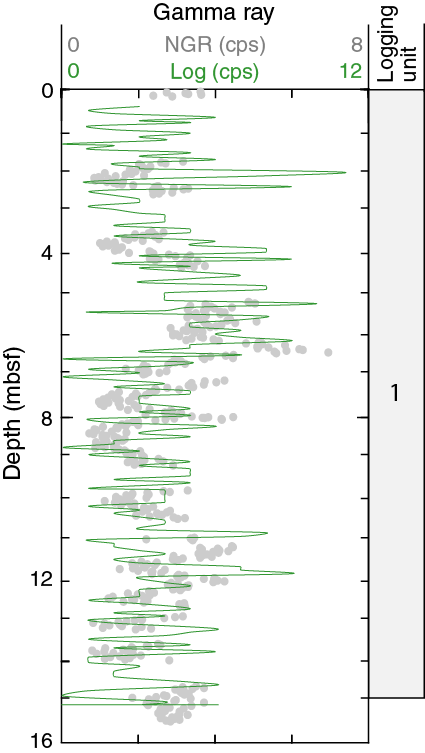
Figure F40. Total gamma ray downhole logging through pipe and core data, Hole M0076B.
Core-log correlations
NGR measurements were also acquired on the core material recovered from Hole M0076B (see Physical properties). These measurements are based on the same principle as that which the gamma sensor of the OAG tool is based (see Downhole logging and Physical properties, both in the Expedition 357 methods chapter [Früh-Green et al., 2017b]). However, a combination of the volume of material being measured, the lateral and vertical heterogeneity of the geology, and core recovery makes it complicated to reconcile the two data sets. That said, there do seem to be certain similarities in the downhole profiles of the core and logging gamma ray data (Figure F40), although depth matching the core data set to the downhole logs would likely improve this comparison.
Paleomagnetism
To achieve the main paleomagnetic objectives, magnetic susceptibility measurements (κ) and rudimentary analyses of natural remanent magnetization (NRM) were made on discrete specimens of known volume and mass (see Paleomagnetism in the Expedition 357 methods chapter [Früh-Green et al., 2017b]). Discrete samples were collected from Holes M0069A (three samples), M0072B (one sample), and M0076B (two samples). The magnetic susceptibility measured in these samples ranges from 0.00065 to 0.03706 SI units (Table T16). The lowest susceptibility values are found in a metadolerite and a talc-amphibole-chlorite schist from the shallower sections of Hole M0069A; the highest value corresponds to serpentinized harzburgite.
Table T16. Magnetic susceptibility and NRM inclinations of discrete samples, Sites M0069, M0072, and M0076. Download table in .csv format.
The NRM direction and intensity of these discrete samples were measured using the 2G-Enterprises SRM 755–4000 magnetometer. Results indicate that an alternating field (AF) of 5–20 mT is sufficient to remove a weak viscous remanent magnetization (VRM) for all samples from the central sites. There were two different responses to this sequential AF demagnetization (Figures F41, F42). Some samples lost 50% of their NRM intensity at alternating fields less than 40 to 50 mT (i.e., Samples 357-M0069A-10R-1, 82 cm, and 357-M0076B-8R-1, 87.5 cm, and 6R-1, 123.5 cm). Other samples (i.e., Samples 357-M0069A-8R-1, 112 cm, and 357-M0072B-8R-1, 28 cm) showed demagnetization typified by a paleomagnetic vector that is smoothly demagnetized up to the maximum alternating field demagnetization level of 100 mT, with a vector that does not trend toward the origin of the orthogonal projection. This magnetic behavior indicates that a characteristic remanent magnetization (ChRM) cannot be isolated, and it is therefore not possible to determine the inclination.
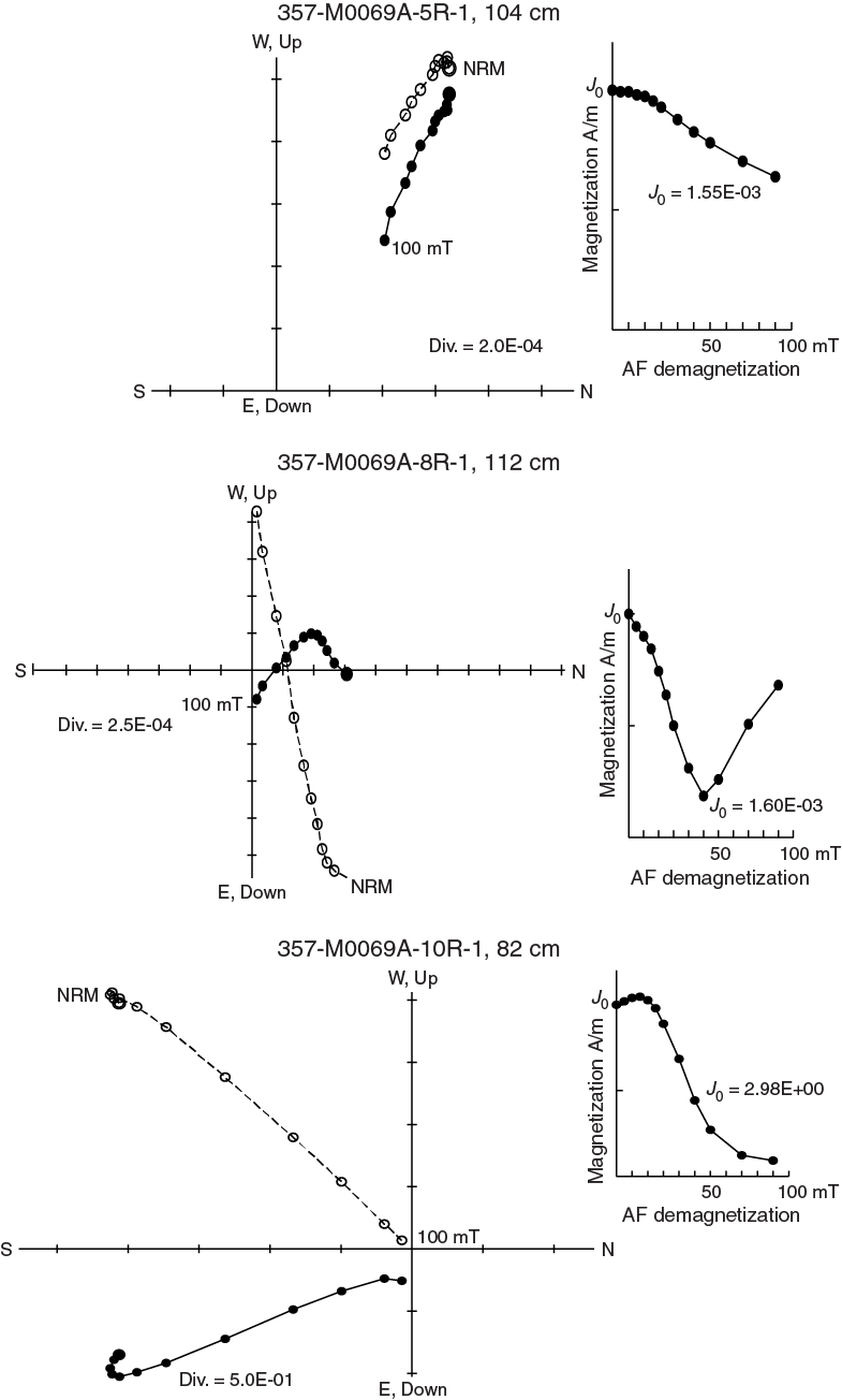
Figure F41. Typical AF progressive demagnetization for three samples, Hole M0069A.
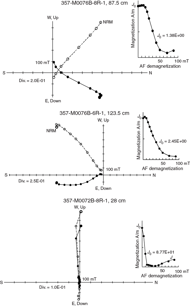
Figure F42. Typical AF progressive demagnetization, Sites M0072 and M0076.
The paleomagnetic stability of the first category of samples was suitable for alternating field demagnetization, and it is possible to isolate a ChRM. Sections 357-M0069A-5R-1 and 10R-1 are associated with inclinations that approach the geocentric axial dipole (GAD) prediction of –49° for these sites (Table T16). The sample from Section 357-M0072B-8R-1 is characterized by an inclination value about 8.6° higher with respect to the GAD value. For Section 357-M0076B-6R-1, inclination is –49.1°, which is in agreement with the expected GAD value, and Section 8R-1 is characterized by an inclination of –40.8°, which is about 8.2° lower than the predicted value of the GAD model. Except for Section 357-M0069A-8R-1, where the inclination could not be determined, the other inclination values could plausibly be used for relative dating purposes.
References
Blackman, D.K., Karson, J.A., Kelley, D.S., Cann, J.R., Früh-Green, G.L., Gee, J.S., Hurst, S.D., John, B.E., Morgan, J., Nooner, S.L., Ross, D.K., Schroeder, T.J., and Williams, E.A., 2002. Geology of the Atlantis Massif (Mid-Atlantic Ridge, 30°N): implications for the evolution of an ultramafic oceanic core complex. Marine Geophysical Research, 23(5–6):443–469. http://dx.doi.org/10.1023/B:MARI.0000018232.14085.75
Früh-Green, G.L., Orcutt, B.N., Green, S.L., Cotterill, C., Morgan, S., Akizawa, N., Bayrakci, G., Behrmann, J.-H., Boschi, C., Brazelton, W.J., Cannat, M., Dunkel, K.G., Escartin, J., Harris, M., Herrero-Bervera, E., Hesse, K., John, B.E., Lang, S.Q., Lilley, M.D., Liu, H.-Q., Mayhew, L.E., McCaig, A.M., Menez, B., Morono, Y., Quéméneur, M., Rouméjon, S., Sandaruwan Ratnayake, A., Schrenk, M.O., Schwarzenbach, E.M., Twing, K.I., Weis, D., Whattam, S.A., Williams, M., and Zhao, R., 2017a. Eastern sites. In Früh-Green, G.L., Orcutt, B.N., Green, S.L., Cotterill, C., and the Expedition 357 Scientists, Atlantis Massif Serpentinization and Life. Proceedings of the International Ocean Discovery Program, 357: College Station, TX (International Ocean Discovery Program). http://dx.doi.org/10.14379/iodp.proc.357.103.2017
Früh-Green, G.L., Orcutt, B.N., Green, S.L., Cotterill, C., Morgan, S., Akizawa, N., Bayrakci, G., Behrmann, J.-H., Boschi, C., Brazelton, W.J., Cannat, M., Dunkel, K.G., Escartin, J., Harris, M., Herrero-Bervera, E., Hesse, K., John, B.E., Lang, S.Q., Lilley, M.D., Liu, H.-Q., Mayhew, L.E., McCaig, A.M., Menez, B., Morono, Y., Quéméneur, M., Rouméjon, S., Sandaruwan Ratnayake, A., Schrenk, M.O., Schwarzenbach, E.M., Twing, K.I., Weis, D., Whattam, S.A., Williams, M., and Zhao, R., 2017b. Expedition 357 methods. In Früh-Green, G.L., Orcutt, B.N., Green, S.L., Cotterill, C., and the Expedition 357 Scientists, Atlantis Massif Serpentinization and Life. Proceedings of the International Ocean Discovery Program, 357: College Station, TX (International Ocean Discovery Program). http://dx.doi.org/10.14379/iodp.proc.357.102.2017
Früh-Green, G.L., Orcutt, B.N., Green, S.L., Cotterill, C., Morgan, S., Akizawa, N., Bayrakci, G., Behrmann, J.-H., Boschi, C., Brazelton, W.J., Cannat, M., Dunkel, K.G., Escartin, J., Harris, M., Herrero-Bervera, E., Hesse, K., John, B.E., Lang, S.Q., Lilley, M.D., Liu, H.-Q., Mayhew, L.E., McCaig, A.M., Menez, B., Morono, Y., Quéméneur, M., Rouméjon, S., Sandaruwan Ratnayake, A., Schrenk, M.O., Schwarzenbach, E.M., Twing, K.I., Weis, D., Whattam, S.A., Williams, M., and Zhao, R., 2017c. Expedition 357 summary. In Früh-Green, G.L., Orcutt, B.N., Green, S.L., Cotterill, C., and the Expedition 357 Scientists, Atlantis Massif Serpentinization and Life. Proceedings of the International Ocean Discovery Program, 357: College Station, TX (International Ocean Discovery Program). http://dx.doi.org/10.14379/iodp.proc.357.101.2017
McDonough, W.F., and Sun, S.-S., 1995. The composition of the Earth. Chemical Geology, 120(3–4):223–253. http://dx.doi.org/10.1016/0009-2541(94)00140-4
Sun, S.-S., and McDonough, W.F., 1989. Chemical and isotopic systematics of oceanic basalts: implications for mantle composition and processes. In Saunders, A.D., and Norry, M.J. (Eds.), Magmatism in the Ocean Basins. Geological Society Special Publication, 42:313–345. http://dx.doi.org/10.1144/GSL.SP.1989.042.01.19
1 Früh-Green, G.L., Orcutt, B.N., Green, S.L., Cotterill, C., Morgan, S., Akizawa, N., Bayrakci, G., Behrmann, J.-H., Boschi, C., Brazelton, W.J., Cannat, M., Dunkel, K.G., Escartin, J., Harris, M., Herrero-Bervera, E., Hesse, K., John, B.E., Lang, S.Q., Lilley, M.D., Liu, H.-Q., Mayhew, L.E., McCaig, A.M., Menez, B., Morono, Y., Quéméneur, M., Rouméjon, S., Sandaruwan Ratnayake, A., Schrenk, M.O., Schwarzenbach, E.M., Twing, K.I., Weis, D., Whattam, S.A., Williams, M., and Zhao, R., 2017. Central sites. In Früh-Green, G.L., Orcutt, B.N., Green, S.L., Cotterill, C., and the Expedition 357 Scientists, Atlantis Massif Serpentinization and Life. Proceedings of the International Ocean Discovery Program, 357: College Station, TX (International Ocean Discovery Program). http://dx.doi.org/10.14379/iodp.proc.357.104.2017
- F1. DSL120 sonar imagery and 50 m resolution multibeam bathymetry, Sites M0069, M0072 and M0076.
- F2. Location of Holes M0072A, M0072B, M0076A, M0076B, and M0069A.
- F3. Lithologic summary for central holes.
- F4. Aphyric vesicle-poor basalt. Coarse clinopyroxene partially includes tabular plagioclase grains.
- F5. Alteration, Hole M0076B.
- F6. Intensely oxidized and serpentinized dunite pieces, carbonate and serpentine veined harzburgite, and subvertical veins cutting serpentinized peridotite.
- F7. Metasomatic alteration of a possibly originally magmatic vein that subvertically crosscuts serpentinized harzburgite.
- F8. Amphibole- and talc-bearing shear zone.
- F9. High-intensity cataclastic deformation in dolerite, steeply dipping composite amphibole and chlorite (± talc) vein cutting serpentinized porphyroclastic harzburgite, and moderately dipping carbonate vein with oxidation cutting pyroxene-poor serpentinized dunite.
- F10. Mineral phases identified by bulk powder XRD analysis, Holes M0076B, M0072B, and M0069A.
- F11. Alteration, Hole M0072B.
- F12. Complex shear zone showing a transition from static alteration to strain localization in alternating talc-, amphibole-, and chlorite-rich shear zones.
- F13. Magmatic intrusion into a fully serpentinized harzburgite. Late metasomatic alteration at the boundary of the mafic/ultramafic rocks produced a white and green talc-amphibole-chlorite assemblage that crosscuts the previous texture.
- F14. Serpentinite partially metasomatized to chlorite-amphibole-talc.
- F15. Fine-grained breccia in contact with a schistose talc-amphibole shear zone hosting brittlely deformed clasts of metadolerite.
- F16. Serpentinized peridotite.
- F17. Serpentinized harzburgite with chromian spinel grain.
- F18. Alteration, Hole M0069A.
- F19. Amphibole-chlorite zone with large metadolerite clast, serpentinized dunite presenting a mesh to ribbon texture underlined by preferentially oriented magnetite concentrations along microfractures, and serpentinized dunite crosscut by multiple carbonate veins bordered by significant oxidation.
- F20. Alteration of pale, irregular, patchy alteration observed in metadolerites. Yellow-brown patches are chlorite rich and cut by epidote veins.
- F21. Deformation and dolerite intrusion, Hole M0069A.
- F22. Cataclasis of a chlorite-rich interval and no consistent foliation.
- F23. Chondrite-normalized REE plot, Holes M0069A and M0072B.
- F24. Primitive mantle–normalized extended trace element plot, Sites M0069, M0072, and M0076.
- F25. Sensor data, Hole M0069A.
- F26. Sensor data, Hole M0072A.
- F27. Sensor data, Hole M0072B.
- F28. Sensor data, Hole M0076A.
- F29. Sensor data, Hole M0076B.
- F30. Borehole plug emplacement, Hole M0072B.
- F31. Equipment left behind in borehole, Hole M0069A.
- F32. Equipment left behind in borehole, Hole M0076B.
- F33. Physical properties, Hole M0076A.
- F34. Physical properties, Hole M0076B.
- F35. Physical properties, Hole M0069A.
- F36. Physical properties, Hole M0072A.
- F37. Physical properties, Hole M0072B.
- F38. Grain density and porosity data from MAD analyses, Holes M0069A, M0072B, and M0076B.
- F39. Geometry of logging from the RD2, Hole M0076B.
- F40. Total gamma ray downhole logging through pipe and core data, Hole M0076B.
- F41. Typical AF progressive demagnetization for three samples, Hole M0069A.
- F42. Typical AF progressive demagnetization, Sites M0072 and M0076.
- T1. Central sites hole summary.
- T2. X-ray diffraction results, Holes M0069A, M0072B, and M0076B.
- T3. Whole-round cores collected for microbiological analysis, Sites M0069, M0072, and M0076.
- T4. Core liner fluid samples for microbiological analyses, Sites M0069, M0072, and M0076.
- T5. Microbial cell abundance counted on flame-sterilized interior piece of rock samples, Sites M0069 and M0072.
- T6. Water samples collected from sensor package Niskin bottles for microbiological analysis, Sites M0069, M0072, and M0076.
- T7. Water samples collected from CTD Rosette Niskin bottles for microbiological analyses, Sites M0069 and M0072.
- T8. Microbial cell abundance counted on water samples, Site M0069.
- T9. Sensor signal time log, Hole M0069A.
- T10. Sensor signal time log, Hole M0072A.
- T11. Sensor signal time log, Hole M0072B.
- T12. Sensor signal time log, Hole M0076A.
- T13. Sensor signal time log, Hole M0076B.
- T14. Physical properties, Sites M0076, M0069, and M0072.
- T15. Grain density, porosity, and P-wave velocity for discrete samples, Sites M0076, M0069, and M0072.
- T16. Magnetic susceptibility and NRM inclinations of discrete samples, Sites M0069, M0072, and M0076.