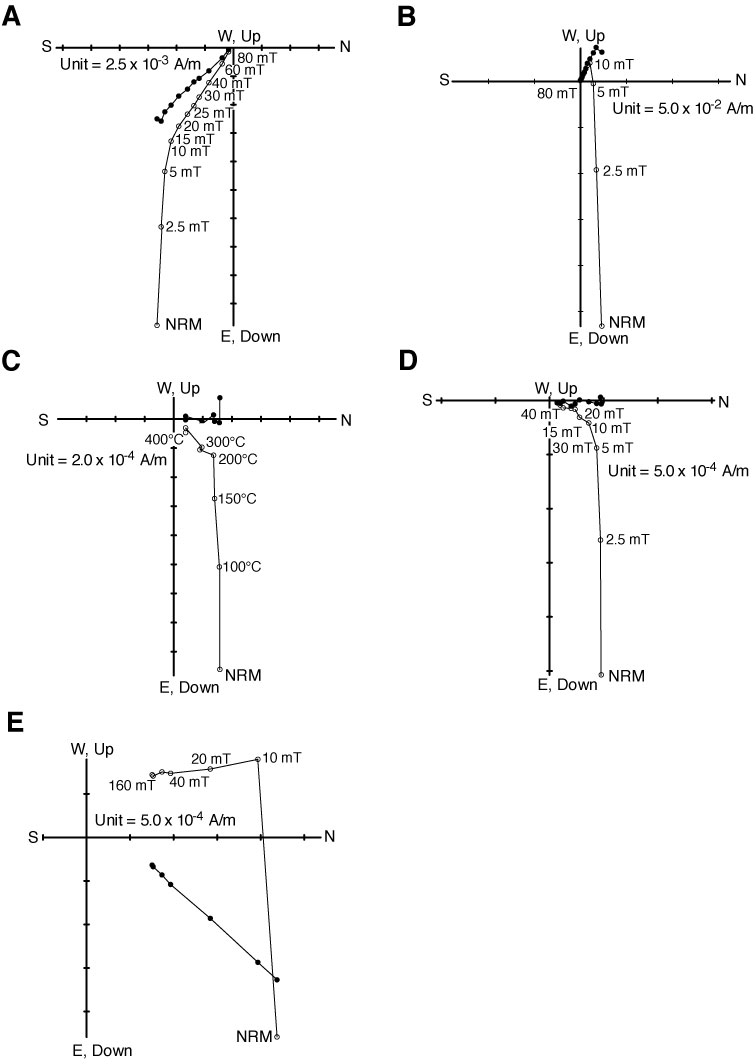
Figure F37. Representative vector endpoint diagrams of magnetization directions through stepwise AF demagnetization or thermal demagnetization. A. Sample 322-C0011B-4R-1, 72–74 cm, and (B) Sample 322-C0011B-7R-1, 118–120 cm, showing isolation of stable normal and reversed ChRM component that is decaying toward the origin of the vector plot after removal of a vertical downward component of DIRM after AF demagnetization at 10 mT. C. Sample 322-C0011B-15R-4, 96–98 cm, shows demagnetization behavior through thermal demagnetization compared with AF demagnetization on (D) Sample 322-C0011B-15R-4, 99–101 cm, which was taken 3 cm below. E. Sample 322-C0011B-49R-7, 74–76 cm, indicating the presence of higher coercivity component, which cannot be completely demagnetized by AF at 160 mT. Open and solid circles = projection of magnetization vector endpoints onto vertical and horizontal planes, respectively. NRM = natural remanent magnetization.
Previous | Close | Next | Top of page