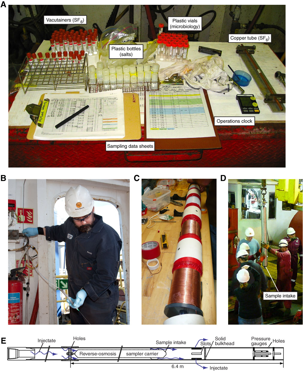
Figure F8. Photographs and drawing of tracer injectate sampling systems. A. Table on rig floor set up with sampling containers and related supplies. Samples were collected to determine concentrations of various tracers added throughout the injection experiment. SF6 samples were collected in preevacuated glass vacutainers and precut lengths of ¼ inch copper tube (crimped during sampling). Microbiology samples were collected in sterile plastic vials. Salt samples were collected in acid-washed HDPE screw-top bottles. Synchronized operations clocks placed on the rig floor, in the mud room (where SF6 was injected), and in the driller’s shack helped to co-register pumping, tracer addition, and sampling events. B. Technician R. Gjesvold collects a rig floor sample using valve plumbed to standpipe adjacent to rig plumbing. C. Preparation of reverse-osmosis (RO) sampler deployed at end of stinger, where fluids exit the drill pipe and enter the formation. Sampler includes RO pumps (at top of image), and two coils each of PTFE and copper tubing (both 1.2 mm ID). D. RO sampler being deployed into carrier at end of stinger on rig floor, prior to reentry of Hole U1362B and start of injection experiment. E. Configuration of pipe positioned at end of stinger (Fig. F2) used to carry the RO sampler and pressure gauges. Slots in the pipe permitted injectate to exit the stinger and enter the formation, and holes into a separate chamber at the base of the pipe allowed downhole pressure gauges to determine borehole fluid pressure.
Previous | Close | Next | Top of page