Früh-Green, G.L., Orcutt, B.N., Green, S.L., Cotterill, C., and the Expedition 357 Scientists
Proceedings of the International Ocean Discovery Program Volume 357
publications.iodp.org
doi:10.14379/iodp.proc.357.105.2017

Western sites1
G.L. Früh-Green, B.N. Orcutt, S.L. Green, C. Cotterill, S. Morgan, N. Akizawa, G. Bayrakci, J.-H. Behrmann, C. Boschi, W.J. Brazelton, M. Cannat, K.G. Dunkel, J. Escartin, M. Harris, E. Herrero-Bervera, K. Hesse, B.E. John, S.Q. Lang, M.D. Lilley, H.-Q. Liu, L.E. Mayhew, A.M. McCaig, B. Menez, Y. Morono, M. Quéméneur, S. Rouméjon, A. Sandaruwan Ratnayake, M.O. Schrenk, E.M. Schwarzenbach, K.I. Twing, D. Weis, S.A. Whattam, M. Williams, and R. Zhao2
Keywords: International Ocean Discovery Program, IODP, RRS James Cook, Expedition 357, Site M0071, Site M0073, seabed drills, RD2, MeBo, Atlantis Massif, Atlantis Fracture Zone, Mid-Atlantic Ridge, Lost City hydrothermal field, serpentinization, detachment faulting, oceanic core complex, hydrogen, methane, deep biosphere, carbon cycling, carbon sequestration, contamination tracer testing
MS 357-105: Published 4 February 2017
Operations
During Expedition 357, coring was attempted at two sites in the western area of Atlantis Massif: Sites M0071 and M0073 (Figure F1; Table T1). However, material was only recovered from Site M0071. Multibeam echo sounder data acquired on this survey, combined with preexisting data sets, were evaluated prior to each site to guide the drill teams with regard to anticipated seabed conditions and slope.
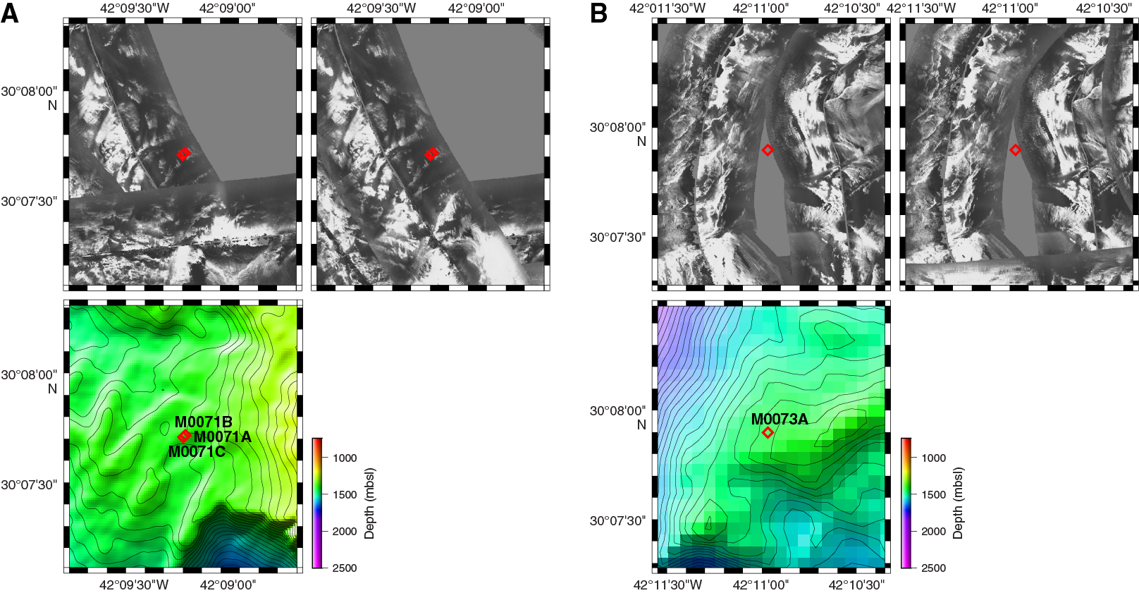
Figure F1. DSL120 sonar imagery and 50 m resolution multibeam bathymetry, Sites M0071 and M0073.
Table T1. Western sites hole summary. Download table in .csv format.
Site M0071
Cores were recovered from three holes at Site M0071 (proposed Site AM-04A), with an average site recovery of 40.78%. The mean water depth for the three sites was 1386.93 m with no tidal range. The total time spent on station was 4.45 days.
Hole M0071A
At 1000 h on 9 November 2015, following discussion with the Co-Chief Scientist on shift, the vessel departed Site M0070 and transited to Site M0071, arriving on station under dynamic positioning (DP) by 1125 h.
At 1400 h, a conductivity, temperature, and depth (CTD) cast was begun. At 1446 h, the CTD was 2.2 m off the bottom, and the first three Niskin bottles were fired. Two further Niskin bottles were fired on the way up, with a final one fired near the surface (see Table T5 in the Expedition 357 summary chapter [Früh-Green et al., 2017c]). The CTD was recovered on deck by 1525 h.
The Meeresboden-Bohrgerät 70 (MeBo) drill was deployed at 1700 h following a delay due to a hydraulic oil leak and landed on the seafloor at 1924 h after a mid–water column systems check. Due to a 19° slope, it was necessary to reposition. The drill lifted off the seafloor, and the vessel moved ahead 10 m. At 2017 h, the MeBo was again on the seafloor, and coring started at 2050 h on 9 November. Two core runs were completed at 0140 and 0230 h on 10 November. However, on recovering the barrel from core Run 2, the overshot wire snapped and the hole had to be aborted; see Borehole plugs for details about the equipment left in the borehole. The MeBo was recovered on deck by 0531 h following a technical issue with the winch slowing recovery, and repairs were started. The British Geological Survey RockDrill2 (RD2) was prepared for deployment. The vessel departed the station at 0532 h.
In summary, two coring attempts were made in Hole M0071A to a maximum depth of 5.22 m with 54.60% recovery.
Hole M0071B
The vessel arrived on station and settled into DP mode at 0952 h on 18 November 2015. Following completion of predive checks, the RD2 was deployed at 1117 h. However, a sensor failure on the tool arm during a mid–water column systems check required the drill to be recovered, and it landed on deck at 1310 h. Because repairs were still ongoing with the MeBo, the vessel stayed on station until the RD2 could be relaunched at this site.
The RD2 was deployed again at 1530 h and landed on the seafloor at 1634 h. After repositioning once because of the slope angle caused by landing on cobbles/boulders, coring commenced at 1720 h. At 2025 h, the tracer pump for the perfluoromethylcyclohexane (PFC) tracer injection was turned off. The power supply was shared with one of the cameras, and interference was increasing and the cameras were dropping out. At 2027 h, when unlatching the core barrel from Run 1, the barrel was dropped; the slope angle caused the barrel to swing away from the tool arm and fall against the rig. The barrel was recovered and stowed safely by 2147 h. The second core run was completed by 0011 h on 19 November, but latching and unlatching core barrels were still problematic because of the angle of the rig. It was therefore decided to deploy core Barrel 3, ream out and lift the bottom-hole assembly (BHA) out of the hole, level the rig, and then ream back into the base of the hole before recommencing coring. This process was completed by 0254 h. At 0709 h, the RD2 began suffering hydraulic problems, with a small leak and intermittent control issues. The Niskin bottles were fired. However, due to a blocked gate valve, it was not possible to conduct downhole logging.
The top plug section of the borehole plug was connected to the packer section and inserted into the borehole; however, the stop ring ended up 150 mm above the breakout table. The “J” connector was disconnected from the top plug at 1014 h, and the RD2 was lifted off the seafloor at 1030 h. However, the stop ring caught on the breakout table as the RD2 came off the seafloor, pulling the plug out of the borehole. Details of the borehole plug installation can be found in Borehole plugs. The RD2 was recovered to deck by 1156 h in increasingly rough weather. One leg could not be retracted because of hydraulic problems, so one of the Launch and Recovery System (LARS) base plates was removed to set the drill level on the vessel. Coring operations were put on “waiting on weather” status, and the vessel left the site at 1226 h on 19 November to begin running multibeam surveys.
In summary, three coring attempts were made in Hole M0071B to a maximum depth of 4.30 m with 53.60% recovery.
Hole M0071C
The vessel arrived on station at 1515 h on 25 November 2015 having completed operations in Hole M0068B. MeBo deployment began at 1529 h, and the drill was on the seafloor in a stable position at 1723 h. Coring operations commenced at 1802 h with a slight pause in operations between 1808 and 1810 h because the BHA looked bent. The first core run was completed at 2015 h. At 2115 h, a full reboot of the MeBo was performed, causing disruption to the sensor package data stream. This stream was restarted at 2128 h. Coring continued throughout 26 November with core Runs 2–5 recovered at 0425, 1047, 1620, and 2105 h. However, an issue developed with the sensor logger because of the systems reboot performed on 25 November. The package lost connection to external power until 0400 h on 27 November, coinciding with core Run 2. Following this run, the sensor logger remained stable.
Core Run 6 was completed on 27 November at 0800 h after difficult drilling conditions and very slow penetration. Core Barrel 7 was deployed and reaming back to the base of the hole commenced, but progress remained very slow. At 1140 h, it was decided to trip the drill rods and change to a new BHA. On recovery (1315 h), it was discovered that Barrel 7 was not latched into the BHA. A new BHA with a G4 bit was deployed at 1330 h. Core Run 8 effectively reamed back down to the base of the hole, where there were problems with hole stability and high torque, and the barrel was recovered at 1915 h. Core Barrel 9 was deployed at 1937 h, and reaming continued from 9.67 meters below seafloor (mbsf) to the base of the original hole at 11.77 mbsf (core Run 6). Core Run 9 then continued to 12.15 mbsf before recovery was attempted at 2225 h. However, the barrel was initially stuck in the BHA, only becoming free at 2345 h after numerous attempts to recover it with the overshot.
At 2355 h on 27 November, it was decided to abandon the hole and begin logging operations and installation of a borehole plug because of concerns regarding hole stability and slow progress. As described in Downhole logging, two through-pipe runs were completed with the spectral gamma ray (SGR) sonde by 0151 h, and the dual induction tool (DIL) was then picked up from the magazine. However, the top drive suffered a hydraulic failure, and the upper chuck would not open. This failure prevented deployment of the DIL and recovery of the drill rods and BHA. The equipment left behind in the borehole is described in Borehole plugs. At 0340 h on November 28, the MeBo was lifted off the seafloor, on deck and secure by 0525 h. After removal of the Niskin bottles, the vessel departed from the site at 0536 h on transit toward Site M0075.
In summary, nine coring attempts were made in Hole M0071C to a maximum depth of 12.15 m with 36.54% recovery.
Site M0073
Coring was attempted at one hole at Site M0073 (proposed Site AM-05A); however, there was no recovery. The water depth was 1430.20 m with no tidal range. The total time spent on station was 0.44 days.
Hole M0073A
The vessel first arrived on Site M0073 at 1640 h on 12 November 2015 to conduct a CTD deployment in advance of coring. Drilling operations were on standby due to weather. The CTD was deployed at 1647 h. At 1731 h, the CTD was 1.5 m off the bottom, and the first three Niskin bottles were fired. Two more Niskin bottles were fired on the way up, with a final one firing near the surface (see Table T5 in the Expedition 357 summary chapter [Früh-Green et al., 2017c]). The CTD was recovered on deck at 1812 h. The vessel then left the site to continue a multibeam echo sounder survey covering the western side of the Atlantis Massif complex.
The vessel returned to Hole M0073A at 2242 h on 14 November from Hole M0070B. The MeBo was prepared for deployment while repairs were ongoing with the RD2 due to a communications failure (this turned out to be a software issue requiring a reboot of the electronic control module).
The water sampling system was fitted back into the MeBo, and it was deployed at 0220 h on 15 November and landed on the seafloor at 0413 h. The seafloor was strewn with cobbles/boulders, causing leveling issues for the MeBo rig due to high slope angles upon landing. The MeBo was repositioned three times before finally settling on site at 0455 h and beginning coring operations. There were some concerns regarding the stability of the graphical unit interface (GUI) on the MeBo controlling system, potentially affected by feedback from the high slope angles.
At 0615 h, the MeBo team discovered that the base plate was damaged, causing the port side leg to bend in and preventing the top drive from passing at the end of core Run 1. Coring operations were aborted, and the MeBo was recovered on deck by 0909 h. Repairs to the RD2 were ongoing, with the ram for the headshift requiring replacement following the discovery of a bent top pin preventing full extension. This process was expected to take until midday, and it was decided to transit to Site M0076, with the vessel departing Site M0073 at 0909 h on 15 November.
In summary, one coring attempt was made in Hole M0073A to a maximum depth of 2.20 m with no recovery.
Lithology, alteration, and structure
Coring was attempted at two sites on the western edge of the southern ridge of the Atlantis Massif (see Operations)—Sites M0071 and M0073—but core was only recovered at Site M0071. Site M0071 is located west of the Lost City hydrothermal field and includes three holes (Figure F2). Hole M0071A was drilled to 5.22 mbsf and recovered 2.85 m of core (54.6% recovery); Hole M0071B was drilled to 4.31 mbsf and recovered 2.31 m (53.6% recovery); and Hole M0071C was drilled to 12.15 mbsf and recovered 4.44 m (30.3% recovery) (Figure F3). There is no lithostratigraphic correlation between these holes, and based on the recovered material described below, it is likely that all three holes drilled blocks of rubble.

Figure F2. Location of Holes M0071A–M0071C.
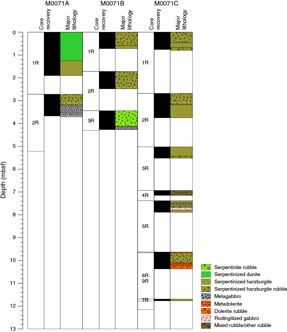
Figure F3. Core recovery and lithology, Site M0071.
The three holes have common lithologic characteristics: the dominant hard rock lithologies are serpentinized harzburgite (with an interval of serpentinized dunite in Hole M0071A) and gabbroic rocks (with intervals of metadolerite in Hole M0071C). These lithologies are undeformed to little deformed. There are several intervals of fragmented rock in grayish green mud (Holes M0071B and M0071C), but these intervals do not show foliation. Serpentinization and oxidation are the main types of alteration present at Site M0071. In some sections (e.g., 357-M0071C-1R-1), localized talc-amphibole-chlorite metasomatism occurs in serpentinized harzburgites.
Section 357-M0071A-1R-1 contains long coherent pieces of oxidized serpentinized dunite with carbonate veins. The upper 4 cm of the core is locally greenish and probably contains metagabbroic material. The core catcher contains a piece of green fully serpentinized harzburgite. Section 1R-2 is also oxidized serpentinized dunite with carbonate veins grading into green serpentinized harzburgite that is brecciated and cemented by carbonate between 25 and 45 cm. Serpentinized dunite is brecciated in the upper 1 cm of the core. Between 97 and 102 cm is an interval of undeformed metagabbro. Core 2R contains green serpentinized harzburgite rubble down to a coherent piece of gabbro from 48 cm to the bottom of the core. Similar gabbro pieces were recovered in the core catcher (3.58–3.71 mbsf).
Three cores were drilled at Hole M0071B, and they recovered rubble of serpentinized harzburgite with gabbroic veins (Section 1R-CC and interval 2R-1, 22–26 cm), one pyroxenite vein (interval 3R-1, 60–65 cm), and one longer gabbroic piece (interval 3R-1, 70–83 cm, to the bottom of the core; 4.27 mbsf).
Nine cores were drilled at Hole M0071C, recovering loose rubble of serpentinized harzburgite and gabbro (Sections 1R–5R) and metadolerite. Some fragments of serpentinized harzburgite are >10 cm long and display thin anastomosing white serpentine veins (Core 1R) or arrays of longer green serpentine veins (Core 2R). Metadolerite is found in Core 6R and below, including a long piece in Core 6R that contains several sheared amphibole- and chlorite-bearing intervals.
Rock types and igneous petrology
Cores recovered at Site M0071 consist principally of serpentinized harzburgites and serpentinized dunites with intervals of metagabbro and evidence for metagabbroic infiltration into ultramafic rocks. Rubble sections are common throughout, and ultramafic lithologies stratigraphically overlie a drilled interval of metadolerite. Overall, the site appears to have drilled through a large ultramafic-dominated boulder on the surface of Atlantis Massif. The igneous petrology of Holes M0071A–M0071C is summarized on a core-by-core basis below (see VCDs in Core descriptions).
Hole M0071A
Section 357-M0071A-1R-1 is a single unit of chromian spinel–bearing (up to 3 mm; present as trails, e.g., at 9, 19, and 26 cm), mesh-textured serpentinized dunite. A completely altered metagabbroic vein occurs between 0 and 5 cm. Section 1R-2 is made up of two units of ultramafic lithologies. Unit 1 is serpentinized dunite, and Unit 2 is serpentinized harzburgite. Unit 1 contains disseminated trails of chromian spinel (grains to 2 mm). At the bottom of Unit 1, between 60 and 67 cm, the modal percentage of orthopyroxene/bastite gradually increases. The upper part of Unit 2 was brecciated in situ, with angular fragments of serpentinized harzburgite set in a carbonate matrix. The upper contact of Unit 2 is within the bastite-rich base of Unit 1. Bastite within the serpentinized harzburgite is ≈3 mm in size and has a modal abundance of 20%–30%. Unit 2, 97–102 cm, is defined by medium-grained clinopyroxene-rich gabbro with patchy domains of clinopyroxene-troctolite. The core catcher also consists of serpentinized harzburgite with ≈6 mm bastite grains that make up 25%–30% of the mode.
The serpentinized dunite in this core contains irregular-shaped chromian spinels that form a train (spinel grains up to 1 mm; interval 1R-1, 9–11.5 cm). The spinel grains are typically strongly altered to oxides (possibly ferrite chromite), although primary oxides are locally preserved in the center of some coarse-grained spinels. In the following section, serpentinized harzburgite displays high degrees of serpentinization and contains up to 25% bastites modally (up to 4 mm; interval 1R-2, 88–92 cm). Irregular-shaped chromian spinel grains are spatially associated with bastites.
Core 2R consists of serpentinized harzburgite rubble (Unit 1) and metagabbro (Unit 2). Bastites in the serpentinized harzburgite are ≈6 mm in diameter (20% modal abundance). The metagabbro is medium grained, containing clinopyroxenes ≈6 mm in diameter (and up to 10 mm poikilitic clinopyroxene), and strong chloritization was observed in thin section (Sample 2R-1, 64–67 cm). The core catcher also contains metagabbro, with coarse-grained (up to 12 mm) pyroxene-rich domains similar to the gabbroic intervals in Core 1R. Irregular leucocratic domains may be products of later, more evolved melts.
Hole M0071B
Core 357-M0071B-1R consists of a single unit of rubble dominated by angular pieces of mesh-textured serpentinized harzburgite (up to 6 cm) and lesser talc-amphibole fragments. Bastite within the serpentinized harzburgite is up to 3 mm in diameter. The core catcher contains mesh-textured serpentinized harzburgite with gabbroic veins. Extensive alteration of serpentinized harzburgite is also confirmed by thin section observation (Sample 1R-2, 88–92 cm). Orthopyroxenes are altered to bastite (≈20% modal abundance), which is spatially associated with chromian spinel (Figure F4). Chromian spinels are vermicular, which strongly indicates magma/mantle interaction, with incongruent melting of orthopyroxene and precipitation of chromian spinel and olivine, similar to many mantle-dominated sequences at slow-spreading ridges.

Figure F4. Serpentinized harzburgite with vermicular chromian spinel.
Core 2R contains a single unit of highly fractured serpentinized harzburgite. The intervals of locally leucocratic metagabbro (22–30 and 35–45 cm) are highly fragmented and highly altered. The core catcher consists of rubble of up to 4 cm fragments of mesh-textured serpentinized harzburgite.
Core 3R contains serpentinized peridotite rubble (Unit 1) and metagabbro (Unit 2). The first fragment of Unit 1 at 20–22 cm is serpentinized dunite with ≈2 mm long bastites with up to 10% modal abundance. Interval 3R-1, 58–63 cm, contains a layer of pyroxenite (orthopyroxene to 10 mm; clinopyroxene to 8 mm). Interval 3R-1, 69–83 cm, consists of an intensively altered metagabbro with relict pyroxenes of the order of 5 mm. In the following unit, metagabbro is extensively altered to chlorite, amphibole, and secondary plagioclase similar to that above (pyroxenes with grain sizes of ≈5–7 mm). Interval 3R-1, 80–83 cm, contains rubble of metagabbro and serpentinized harzburgite.
Hole M0071C
Core 357-M0071C-1R includes two units. Unit 1 is composed of rubble of serpentinized harzburgite and metagabbro. The smaller rubble fragments of serpentinized harzburgite contain 10%–20% modal bastite (up to ≈6 mm in diameter). Unit 2 comprises two large fragments of serpentinized harzburgite, whereas the core catcher consists of rubble of ribbon-textured serpentinized harzburgite similar to that found in Core 1R.
Core 2R contains angular to subrounded fragments of serpentinized harzburgite (Unit 1) and a coherent piece of serpentinized harzburgite with weak porphyroclastic fabric (Unit 2). The core catcher contains similar material consisting of serpentinized harzburgite with a moderate porphyroclastic fabric. The serpentinized harzburgite exhibits an oxidized serpentine mesh texture and contains elongate bastites up to 5 mm long.
Core 3R consists of angular to rounded fragments of serpentinized harzburgite (Unit 1; bastites are 6–10 mm in diameter with ≈25% modal abundance) and subangular to subrounded rubble of serpentinized harzburgite with very weak porphyroclastic fabric (Unit 2).
Core 4R has a bimodal assemblage of subangular fragments (up to 4 cm in size) of metagabbro and serpentinized harzburgite.
Five units of various mafic and ultramafic rocks were identified in Core 5R. Unit 1 is composed of fragments of serpentinized harzburgite (bastites to 4 mm), and Unit 2 consists of highly altered metagabbro. Units 3 and 4 comprise serpentinized harzburgite and rubble of serpentinized harzburgite, respectively, and Unit 5 consists of rodingitized gabbro. The core catcher is composed of serpentinized harzburgite.
Two units of metadolerite and metadolerite rubble were recovered in Core 6R. Within the upper unit, fine- to medium-grained metadolerite contains plagioclase laths. Clinopyroxene is commonly replaced by amphibole. Subhedral plagioclase phenocrysts up to 5 mm in diameter have a modal abundance of ≈3%, with clinopyroxene phenocrysts up to 4 mm at a modal abundance of ≈1%. The lower unit contains angular fragments of metadolerite.
Cores 7R and 8R did not recover any material other than the core catcher (Section 7R-CC), which consists of a single 6 cm fragment of serpentinized harzburgite with bastites up to 8 mm in diameter.
Core 9R recovered rubble of serpentinized harzburgite with subordinate clasts of metagabbro (Unit 1) and a large fragment of metadolerite (Unit 2).
Alteration
Site M0071 includes three holes (Holes M0071A–M0071C) with no lithostratigraphic correlations. The rocks recovered are not considered to be in situ and were all interpreted as rubble clasts with local areas of carbonate matrix (unconsolidated or cemented). This interpretation prevents any general interpretation of the alteration evolution at this site. The main lithologies in the three holes are serpentinized dunite and harzburgite with minor gabbro and metadolerite. Serpentinization and oxidation are the main types of alteration present at Site M0071 (Figures F5, F6). In some sections (e.g., 357-M0071C-1R-1), localized talc-amphibole-chlorite metasomatism occurs in the serpentinized harzburgites.
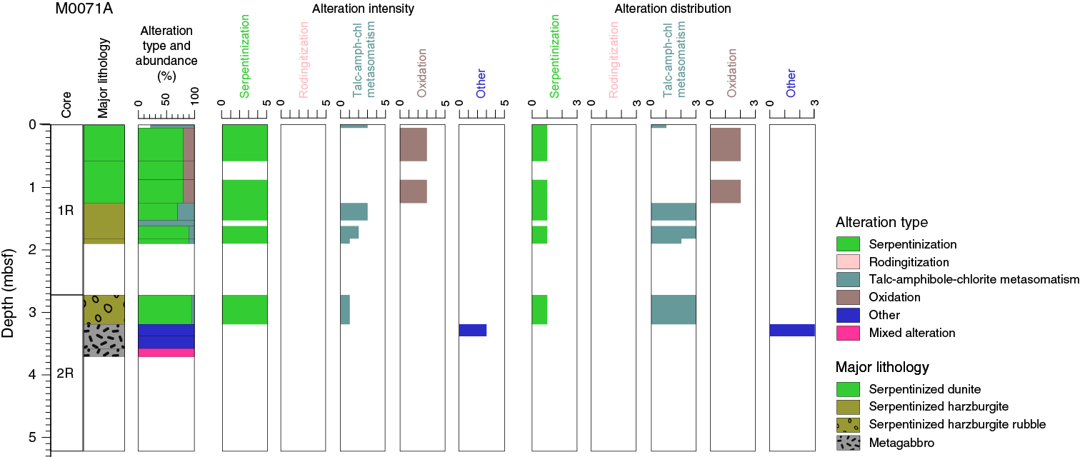
Figure F5. Alteration, Hole M0071A.
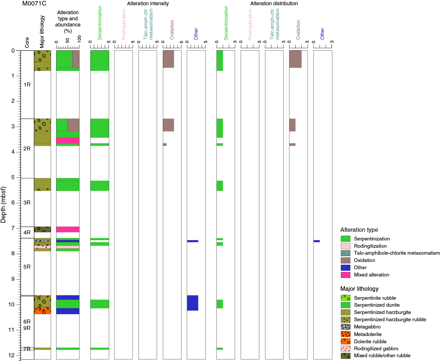
Figure F6. Alteration, Hole M0071C.
Serpentinization
Serpentinization of dunite and harzburgite leads to a variety of colors ranging from pale to dark green with some pale green to brown areas associated with areas of oxidation (Figure F7). Mesh- and ribbon-shaped textures after olivine and bastite after orthopyroxene are commonly observed in the recovered clasts at macroscopic and microscopic scales (e.g., Sample 357-M0071C-2R-1, 74–76 cm) (Figure F8). XRD analyses confirm the predominance of serpentine minerals (including antigorite; Sample 357-M0071B-1R-1, 14–15 cm) in association with magnetite and minor talc, chlorite, or carbonates (e.g., Samples 357-M0071C-1R-1, 44–46 cm, and 2R-1, 74–76 cm, and 357-M0071A-1R-1, 9–11 cm) (Table T2). The intensity of serpentinization ranges from very high (with some relict orthopyroxene locally) to complete and pervasive.

Figure F7. Fully serpentinized dunite with serpentine mesh texture overprinted by carbonate veins with associated oxidation halos.
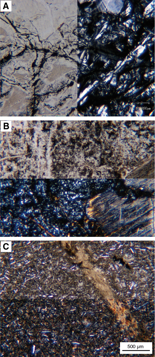
Figure F8. Mineralogical assemblages within rubble pieces, Site M0071.
Table T2. X-ray diffraction results, Site M0071. Download table in .csv format.
Talc-amphibole-chlorite metasomatism
Talc-amphibole-chlorite metasomatism produces pale green to white colors and occurs as localized alteration in very few intervals. An example of metasomatic overprint of bastite to talc is present in interval 357-M0071C-1R-1, 45–70 cm. This style of alteration may also be present in other rubble intervals. Similarly, pieces representing mafic/ultramafic contacts are randomly dispersed throughout Site M0071 within rubble intervals. These pieces are variably metasomatized with different talc-amphibole-chlorite mineral assemblages depending on the protolith (e.g., Sample 357-M0071A-2R-1, 64–67 cm) (Figure F8). One example (Sample 1R-1, 0–3 cm) shows a mafic intrusion in serpentinized dunite that is altered to talc, amphibole, and chlorite.
Oxidation
Localized to pervasive late oxidation is observed at Site M0071 and produces reddish colors. Localized oxidation occurs mainly in Hole M0071A (serpentinized dunite in Sections 1R-1 and 1R-2) in association with carbonate veins and forms millimeter- to centimeter-sized halos around the veins (Figure F7). Pervasive oxidation affects some serpentinized fragments, mostly in Hole M0071C.
Other
Hydrothermal alteration of gabbro and dolerite produces a pale gray color with black alteration halos dominated by chlorite. XRD data and thin section observations confirm partial replacement of plagioclase by chlorite in such intervals (e.g., Sample 357-M0071C-6R-1, 55–57 cm) (Figure F8; Table T2).
Veins and crosscutting relationships
Hydrothermal veins are present throughout Site M0071 and are generally white with orange or green colors. Hole M0071A is dominated by 0.5–4 mm veins of carbonate, foraminiferous carbonate sediment, and iron oxyhydroxides that have millimeter to centimeter pale brown halos (e.g., Section 1R-1) (Figure F7). Green chlorite veins are also present in Hole M0071A. In interval 357-M0071C-9R-1, 33–43 cm, metadolerite hosts a crosscutting vein relationship between clay veins crosscut by chlorite-pyrite veins. The alteration halos associated with these veins are multilayered gray halos with a total width of 3–5 mm.
Overprinting relationships and alteration history
Site M0071 has mixed alteration types with a prevalence of serpentinization. However, the lack of coherent core samples and the high frequency of rubble intervals preclude interpretation of the alteration history of this part of the massif.
Overview of mineralogy from XRD data
Samples for XRD analysis were taken from the three holes drilled at western Site M0071 (Figure F9; Table T2). The most dominant phase in all three holes is serpentine (mainly lizardite with some clinochrysotile and once chrysotile and antigorite). Serpentine comprises >50% of the minerals identified in seven of the nine samples analyzed. Chlorite was a significant phase in three of the samples. Talc and amphibole were detected sporadically. Plagioclase, the only primary phase detected, was a significant component of only a single sample from Hole M0071C. Carbonate also occurs in a single sample from Hole M0071A. Minor phases include magnetite and Cr-bearing oxides.
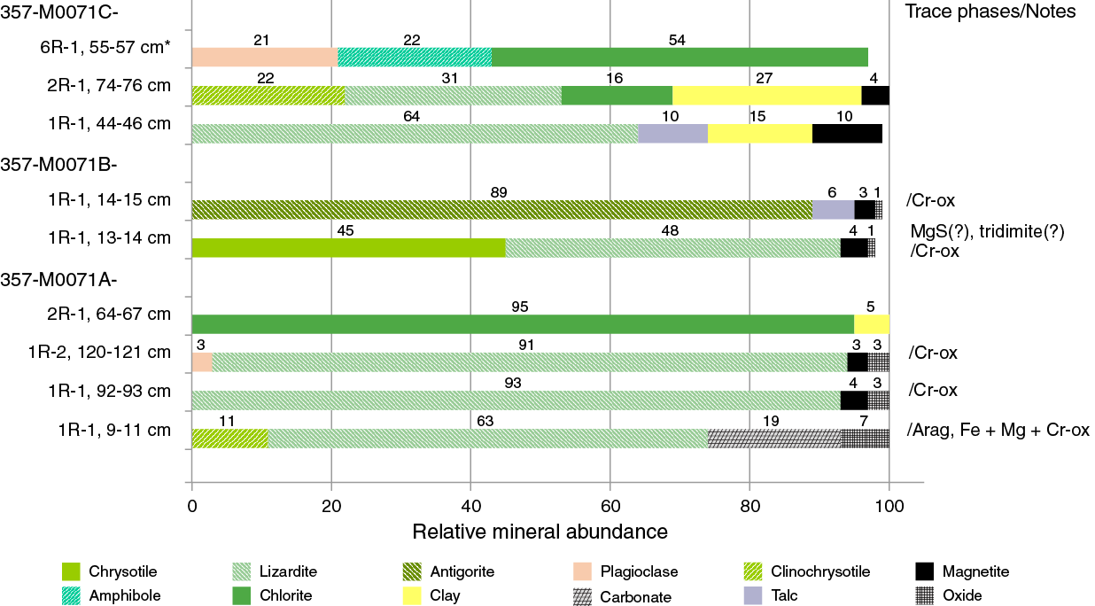
Figure F9. Mineral phases identified by bulk powder XRD analysis, Site M0071.
Structure
Site M0071 is at the western limit of the striated surface in an area with irregular, short (a few hundred meters), low-relief (<10 m) hills oriented oblique (≈45°) to the spreading direction (Figure F2). The three holes drilled at this site are all at the summit of one of these small ridges and are composed of both loose rubble and clasts with a carbonate matrix (both unconsolidated and cemented) that are not considered to be in situ.
Hole M0071A includes an upper interval dominated by large blocks (>20 cm across in Sections 1R-1 and 1R-2) of distinctive oxidized serpentinized dunite with carbonate veins underlain by breccia composed of angular serpentinized peridotite clasts in a carbonate-cemented matrix (to Section 1R-2, 86 cm). A lower structural interval is composed of loose rubble. Clasts are primarily serpentinized peridotite and minor gabbro at the bottom of Section 2R-1. Both structural intervals are not considered in situ.
Hole M0071B consists of a single structural unit composed of breccia with both loose clasts and intervals with a greenish matrix that locally contain carbonate (interval 1R-1, 32–42 cm). Clasts include one gabbro and serpentinized harzburgite cut by gabbroic veins. This single structural unit is likely not in situ.
Hole M0071C also consists of a single structural unit composed primarily of loose clasts of variable size (from >10 cm to <1 mm). An interval of breccia with a greenish matrix is present at interval 1R-1, 30–45 cm.
Bulk rock geochemistry
Bulk carbon analyses
As reported in detail in Bulk rock geochemistry in the Eastern sites chapter (Früh-Green et al., 2017a), the total carbon (TC), total inorganic carbon (TIC), and total organic carbon (TOC) contents of shipboard samples from these sites were measured during the Onshore Science Party and are reported in one table (see Table T3 in the Eastern sites chapter [Früh-Green et al., 2017a]). However, these results should be viewed with caution because samples were taken from existing thin section billet residues.
Whole-rock major and trace elements
Whole-rock major elements and trace elements from western Site M0071 were run together with samples from the other sites and are reported in common tables (measured major and trace elements are in Table T4, and normalized major elements are in Table T5, both in the Eastern sites chapter [Früh-Green et al., 2017a]).
Site M0071
Site M0071 was drilled on the western side of the southern ridge of Atlantis Massif. The site comprises rocks that are considered not in situ but result from mass wasting, as described elsewhere (see Lithology, alteration, and structure). Three serpentinites were analyzed, one of which was macroscopically characterized as serpentinized dunite. The other two are serpentinized harzburgites. The major element compositions of all three serpentinite samples are geochemically similar, but they vary in Ni, Cr, V, and Co, as well as many other trace elements (see Table T4 in the Eastern sites chapter [Früh-Green et al., 2017a]). In particular, Ni concentrations in Sample 357-M0071A-1R-2, 120–121 cm, are the highest measured in all samples and reach nearly 1.5 wt% (see Figure F19 in the Eastern sites chapter [Früh-Green et al., 2017a]), with a correspondingly high Cr content of about 2.2 wt%, reflecting a high modal abundance of chromite. This sample also has pronounced enrichments in V (340 ppm), Co (622 ppm), W (7.62 ppm), and U (5.05 ppm). Trace element compositions of Site M0071 serpentinite samples are relatively depleted, reflecting the ultramafic protolith, and with the exception of low high field strength element (HFSE) abundances and variable fluid mobile element signatures have primitive mantle (PM)–normalized ranges between 0.1 and 1 (Figure F10). In particular, these samples exhibit very strong positive U and Pb anomalies in addition to a potentially pronounced negative Ce anomaly (Ce appears to be near or at the limit of quantification). Site M0071 serpentinite samples are notably depleted in HFSE, including Th (below detection).
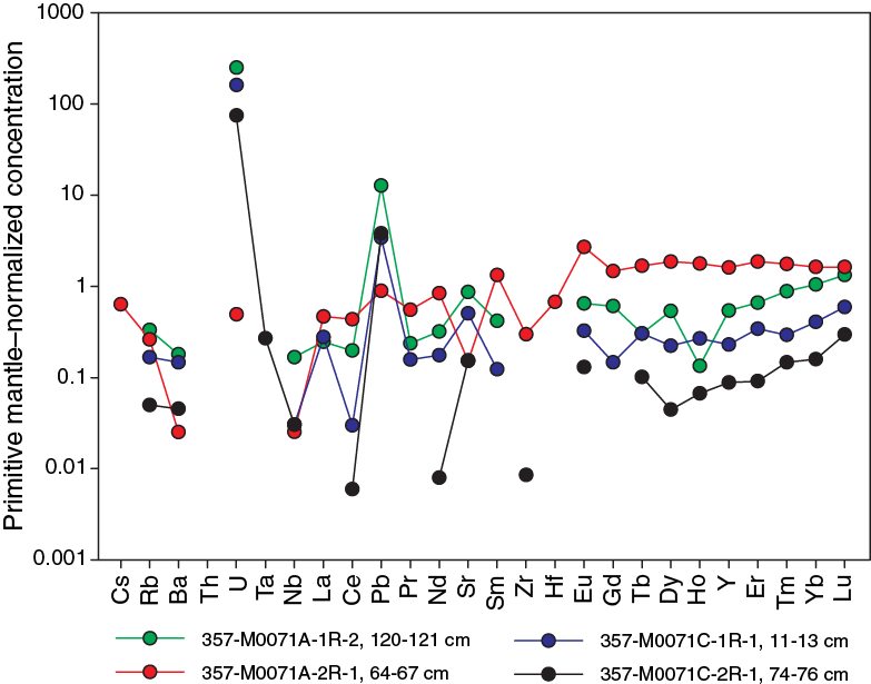
Figure F10. PM–normalized extended trace element plot, Site M0071.
The serpentinized harzburgite sample (357-M0071C-2R-1, 74–76 cm) is more depleted in light rare earth elements (REEs) than all but one other sample from the central sites (Sample 357-M0069A-10R-3, 0–2.5 cm) (Figure F11). In addition, the strongly chloritized metagabbro Sample 357-M0071A-2R-1, 64–67 cm, has the lowest SiO2 (26.21 wt%) and the highest Al2O3 (21.04 wt%) and Fe2O3 (32.07 wt%) concentrations and a low MgO concentration of 14.19 wt%, which is distinct from most of the other sites and suggests strong element mobility and mass transfer during greenschist-facies alteration. Site M0071 samples have a Mg# of 78 and 79, except the one sample of metagabbro/chloritized gabbro (Sample 2R-1, 64–67 cm), which has a particularly low Mg# of 26, which reflects the fact that this sample likely contains high abundances of chlorite and likely iron oxides. Site M0071 samples also contain the highest Li concentrations (up to 22.74 ppm) and some of the highest Pb concentrations (0.13–1.91 ppm; Site M0071 average is 0.78 ppm, whereas the average of the other samples is 0.15 ppm) and Zn concentrations (64.3–395 ppm; Site M0071 average is 277.1 ppm, compared to the average of the other samples, which is 56.1 ppm) (see Table T4 in the Eastern sites chapter [Früh-Green et al., 2017a]).
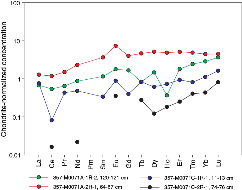
Figure F11. Chondrite-normalized REE plot, Site M0071.
Fluid chemistry
Inorganic and organic fluid chemistry
Cations and anions
As reported in detail in Fluid chemistry in the Eastern sites chapter (Früh-Green et al., 2017a), salinities, major elements, trace elements, and anions measured in fluid samples during the expedition have concentrations comparable to bottom seawater (see Tables T6, T7, T8, and T9 in the Eastern sites chapter [Früh-Green et al., 2017a]). There was no detectable sulfide or ammonia (see Tables T6 and T10 in the Eastern sites chapter [Früh-Green et al., 2017a]).
pH, alkalinity, and dissolved inorganic carbon stable carbon isotopic composition
As reported in detail in Fluid chemistry in the Eastern sites chapter (Früh-Green et al., 2017a), the alkalinity and pH of fluid samples were similar to background seawater at all sites (see Table T11 in the Eastern sites chapter [Früh-Green et al., 2017a]), with the exception of interstitial fluids from carbonate sands from one of the central site locations (see Figure F25 in the Eastern sites chapter [Früh-Green et al., 2017a]).
Volatile chemistry
As reported in detail in Fluid chemistry in the Eastern sites chapter (Früh-Green et al., 2017a), methane concentrations ranged from below the detection limit to 48 µM, and hydrogen concentrations varied from trace levels to 323 µM (see Table T12 in the Eastern sites chapter [Früh-Green et al., 2017a]). Hot spots of hydrogen were observed over Sites M0068–M0072, and hot spots of methane were observed over Sites M0070–M0072 (see Figure F26 in the Eastern sites chapter [Früh-Green et al., 2017a]).
Microbiology
Samples collected
Following the procedure described in detail in Microbiology in the Expedition 357 methods chapter (Früh-Green et al., 2017b), whole-round core (WRC) samples were transferred to the cold room after they were photographed.
At Site M0071, nine WRC samples were collected for microbiological studies: two from Hole M0071A (Sections 1R-2 and 2R-1), two from Hole M0071B (Sections 2R-1 and 3R-1), and five from Hole M0071C (Sections 2R-1, 3R-1, 5R-2, 6R-1, and 9R-1) (Table T3; see MBIOWRC in Supplementary material). We took a few centimeter-sized rock pieces and flame sterilized them for interior PFC tracer, cell count, and single-cell samples. Additional rock pieces from Section 357-M0071B-5R-1 were collected for PFC tracer check, cell count, and gas analyses. These samples were divided into nine unflamed frozen samples, seven enrichment samples, seven exterior PFC samples, five interior PFC samples, eight gas analysis samples, eight exterior cell count samples, six interior cell count samples, and five single-cell analysis samples. Additional exterior cell count samples were taken from the tops of Sections 357-M0071B-2R-1, 3R-1, 5R-1, and 8R-1 and adjacent to the microbiology whole-round sample from Section 3R-1.
Table T3. Whole-round cores collected for microbiological analysis, Site M0071. Download table in .csv format.
Samples sent to Kochi Core Center (Japan) were immediately frozen at –80°C and then shipped under temperature-controlled conditions with constant temperature logging. There, WRC exteriors were cut away with a band saw system equipped in a clean booth and used for PFC tracer check (exterior), concentration and isotopic composition of TIC/TOC, vein analysis, in situ organic carbon and Fe mineral analysis, and trapped-gas analysis. The interior portions of the frozen samples were subjected to shore-based nucleic acid analyses and interior PFC, amino acid, and lipid analyses.
Liner fluid from the core barrels was collected from many cores from each site and was split for PFC, cell count, and organic acid analyses (Table T4).
Table T4. Core liner fluid samples for microbiological analyses, Site M0071. Download table in .csv format.
Contamination assessment with PFC tracer
Samples of liner fluid, sensor package Niskin bottles, and exterior and interior pieces of WRCs were collected to assess contamination by quantifying the concentration of PFC tracer added during drilling operations (see Microbiology in the Expedition 357 methods chapter [Früh-Green et al., 2017b]). Laboratory atmosphere blanks are also reported in Table T15 in the Eastern sites chapter (Früh-Green et al., 2017a) to define lower detection limits; these values varied throughout the expedition because of buildup of volatilized tracer in the shipboard laboratory. PFC concentrations for samples are reported in picograms PFC per cubic centimeter of sample, and laboratory blanks are reported as picograms PFC per milliliter air.
PFC delivery failed during drilling operations in Holes M0071A and M0071B based on very low or undetectable PFC tracer in all samples. PFC delivery was successful during drilling operations in Hole M0071C, but there were high PFC concentrations (103–105 pg PFC/cm3 sample) in the sensor package Niskin bottle and liner fluid samples (see Table T15 in the Eastern sites chapter [Früh-Green et al., 2017a]). Although exterior pieces of the WRC samples had high levels of tracer, the interior pieces after flame sterilization of the exterior had undetectable tracer concentrations.
Cell abundance determination
Cell abundance was not determined shipboard for Site M0071 samples because of time limitations; these samples will be measured in a shore-based laboratory.
Enrichment and incubation experiments
The growth and activity of microbial communities was studied in rock samples obtained during the expedition using a variety of culture-based approaches. Flame-sterilized pieces of rock material were ground to fine particles under anoxic conditions and distributed into the various incubation vessels (Table T3; see Microbiology in the Expedition 357 methods chapter [Früh-Green et al., 2017b]).
Samples were used in the following ways:
- To study the growth of microorganisms under sulfate-reducing conditions (Sections 357-M0071B-3R-1 and 357-M0071C-2R-1 and 5R-2);
- To study the growth of microorganisms at elevated hydrostatic pressures (Section 357-M0071C-5R-2);
- To evaluate the presence of hydrogenotrophic and/or methanogenic microorganisms, as well as heterotrophic microorganisms, under alkaline, anoxic conditions (Section 357-M0071C-5R-2); and
- To study the assimilation of stable isotope–labeled carbon and nitrogen compounds (Section 357-M0071C-6R-1).
Water samples for microbiological analysis
Water from sensor package Niskin bottles and CTD rosette Niskin bottles was sampled for measurements of PFC, cell counts, and microbial community structure from the various coring locations at Site M0071 (Tables T5, T6) and for many chemical measurements (see Water sampling and sensor package data in the Expedition 357 methods chapter [Früh-Green et al., 2017b]).
Table T5. Water samples collected from sensor package Niskin bottles for microbiological analysis, Site M0071. Download table in .csv format.
Table T6. Water samples collected from CTD rosette Niskin bottles for microbiological analysis, Site M0071. Download table in .csv format.
Sensor package data
Mapping drill data onto the sensor plots for all sites was done graphically, and for records of approximately 1000 min, the potential errors are on the order of ±5 min. Western Site M0071 was too deep for use of the pH/oxidation-reduction potential sensor, and drilling at Site M0073 was unsuccessful with no interesting sensor package signals.
Hole M0071A
A notable aspect of the sensor data in Hole M0071A was the high CH4 background values that dropped from 36 to 24 nM in the upper portion of the hole (Figure F12; Table T7). The only significant sensor signal excursion in this hole was a broad CH4 peak that started at 0328 h during Core 2R drilling and ended at 0545 h long after drilling finished at 0342 h and 5252 mm penetration depth. The peak value for this excursion was 77 nM, which is much higher than what was usually detected in the other holes. The seawater flush pump was turned off at the end of Core 2R, so the CH4 peak represented fluid issuing directly from the hole. The two negative oxygen excursions at the beginning and end of the data were caused by the water column oxygen minimum.
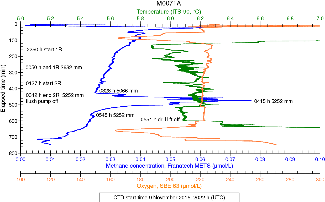
Figure F12. Sensor data, Hole M0071A.
Table T7. Sensor signal time log, Hole M0071A. Download table in .csv format.
Hole M0071B
No CH4 anomalies were associated with this hole (background values = about 0.7 nM), and only slight variations in oxygen and temperature were noted (Figure F13; Table T8).
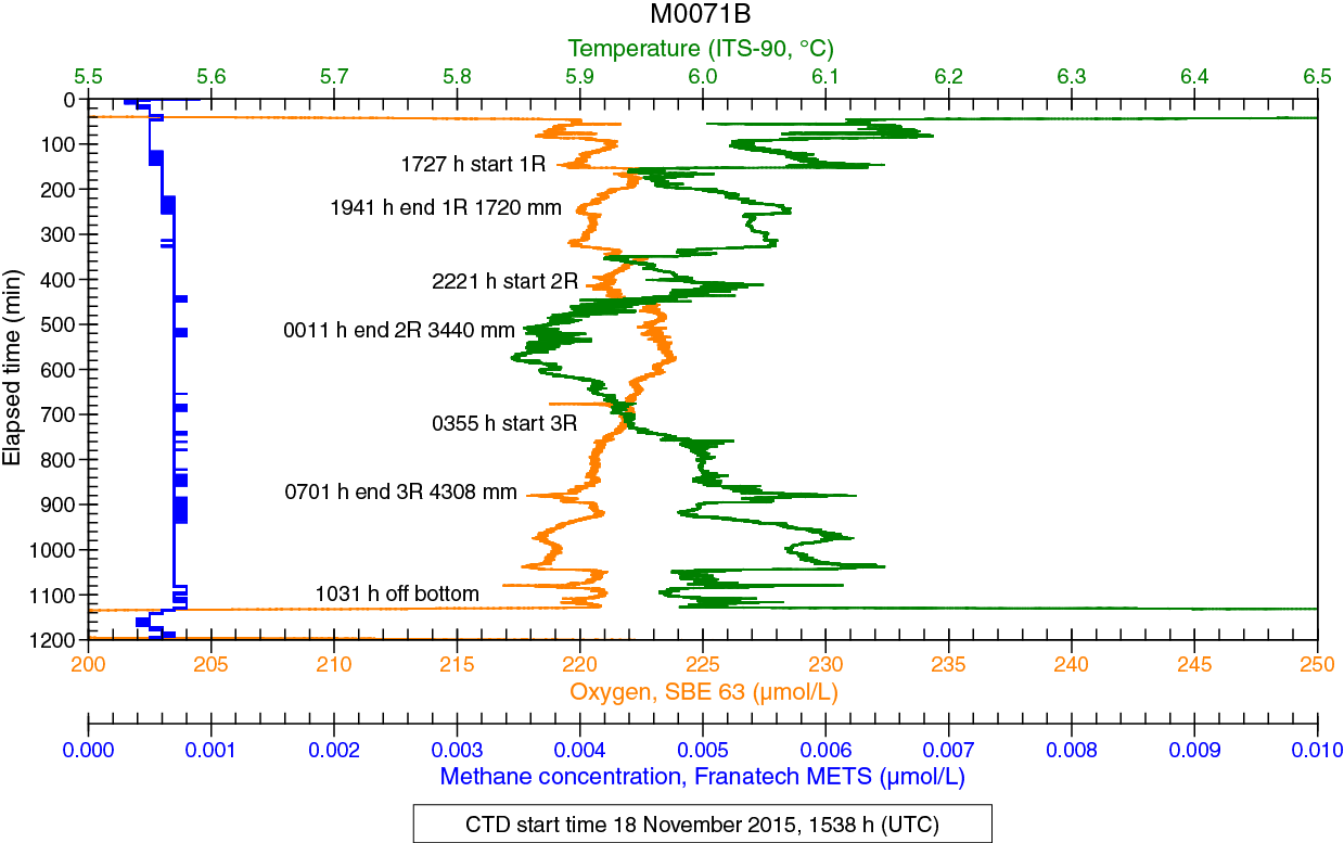
Figure F13. Sensor data, Hole M0071B.
Table T8. Sensor signal time log, Hole M0071B. Download table in .csv format.
Hole M0071C
Sensor data for Hole M0071C are divided into two separate files as the result of a power recycle (Table T9), and the oxygen sensor malfunctioned in this hole. In the first few hours of drilling (Figure F14A), the most significant signal was a sharp CH4 maximum centered at 2018 h (32.8 nM) during Core 1R drilling at 1621 mm penetration depth. Background values were high at this hole and slowly dropped from 24.5 nM at the start of Core 1R to 20.4 nM at the end of the data file. A small CH4 excursion (24.5 nM) at 2324 h occurred during the changeover from Core 1R to Core 2R. An off-scale temperature spike was the result of a data glitch that occurred only on the temperature channel. Cores 3R–9R (Figure F14B) had a large number of sharp CH4 spikes, with concentrations as high as 28.8 nM associated in nearly all cases with positive spikes in temperature. Most of these spikes occurred while drilling specific cores rather than during barrel changes. Drilling ended at 0014 h with Core 9R.
Table T9. Sensor signal time log, Hole M0071C. Download table in .csv format.
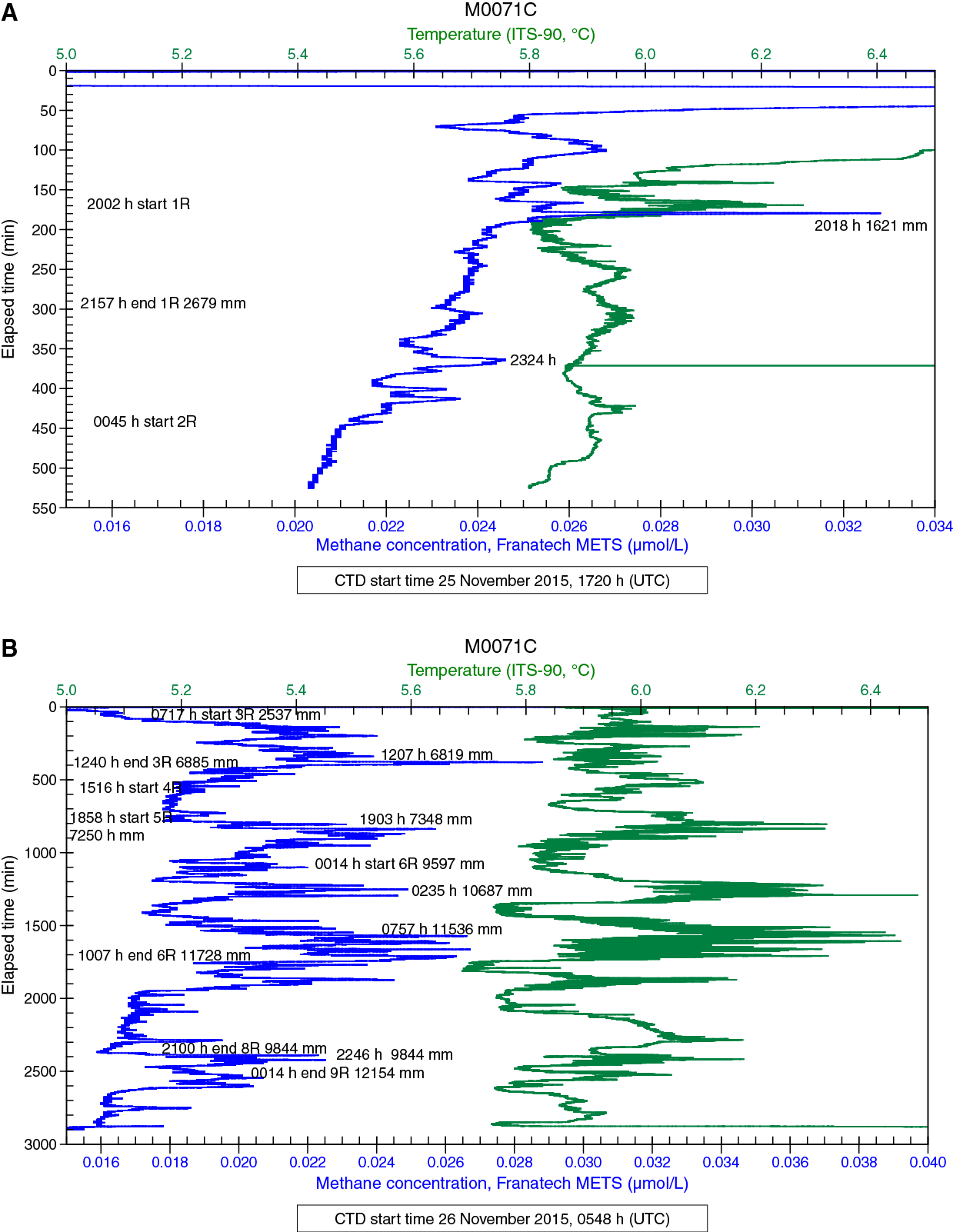
Figure F14. Sensor data, Hole M0071C.
Hole M0073A
Hole M0073A was shallow with no core recovery and no interesting sensor signals.
Borehole plugs
After RD2 drilling operations, one attempt was made to install a borehole plug in Hole M0071B. For further details on borehole plugs, see Borehole plugs in the Expedition 357 methods chapter (Früh-Green et al., 2017b).
In Hole M0071B, a short borehole plug system was inserted into the open hole (Figure F15). The borehole plug consisted of a 2.17 m length of titanium tube with a ball-valve assembly at the upper end connected to a packer element below. Penetration reached 4.3 mbsf. The entire borehole plug assembly was 3.27 m long, with the stop ring set 0.8 m below the top of the assembly. Downhole resistance prevented the stop ring on the borehole packer from insertion below the RD2 breakout table, with the upper section sticking up 1.32 m above the seafloor and the packer element set at 0.85 mbsf. A slight lifting of the system when the RD2 was pulled off of the seafloor occurred, but the packer unit is assumed to still be below the seafloor.
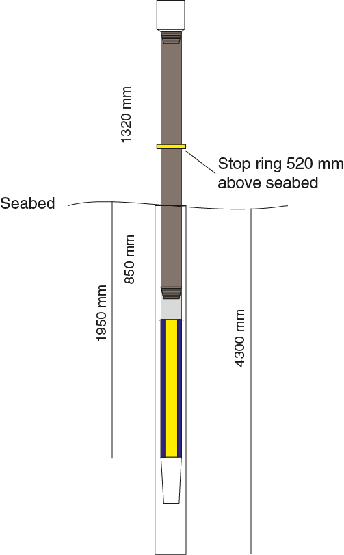
Figure F15. Borehole plug emplacement, Hole M0071B.
Coring equipment was also left in one other hole in the western section. Difficult drilling conditions resulted in the loss of three drill rods and a BHA in Hole M0071C. This 1.04 m length of equipment was stuck at the top of the 12.15 m borehole, so it is possible that 0.8 m of pipe sticks up above the seafloor (Figure F16).
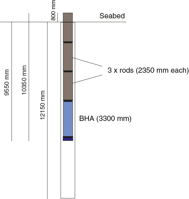
Figure F16. Equipment left behind in borehole, Hole M0071C.
Physical properties
Site M0071
Three holes were cored at Site M0071 with a combined recovery of 9.6 m: ≈55% in Hole M0071A (5.22 mbsf), ≈54% in Hole M0071B (4.31 mbsf), and ≈31% in Hole M0071C (14.26 mbsf).
Density and porosity
Gamma density (GD) measured on whole cores has a mean value of 2.27 g/cm3 and varies between 1.52 and 2.74 g/cm3 (Table T10). Significant scatter in the gamma density profiles in most of the cores across the site is due to the degree of fragmentation of the rocks (Figures F17, F18, F19). Four discrete samples were taken for moisture and density (MAD) measurements: two serpentinites from Holes M0071A (1.80 mbsf; serpentinized dunite) and M0071C (3.23 mbsf; serpentinized harzburgite), one metagabbro from the deepest part of Hole M0071A (3.30 mbsf), and one metadolerite from the base of Hole M0071C (9.77 mbsf) (Table T11). The serpentinites have grain densities of 2.56 g and 2.60 g/cm3 and porosities of 5.7% and 6.9%. The mafic rocks have higher grain densities and lower porosities: 2.72 g/cm3 and 2.9%, respectively, for the metagabbro and 2.88 g/cm3 and 1.8%, respectively, for the metadolerite.
Table T10. Physical properties, Site M0071. Download table in .csv format.
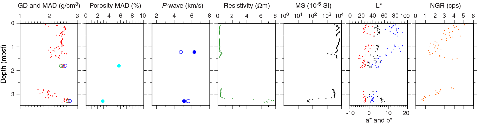
Figure F17. Physical properties, Hole M0071A.
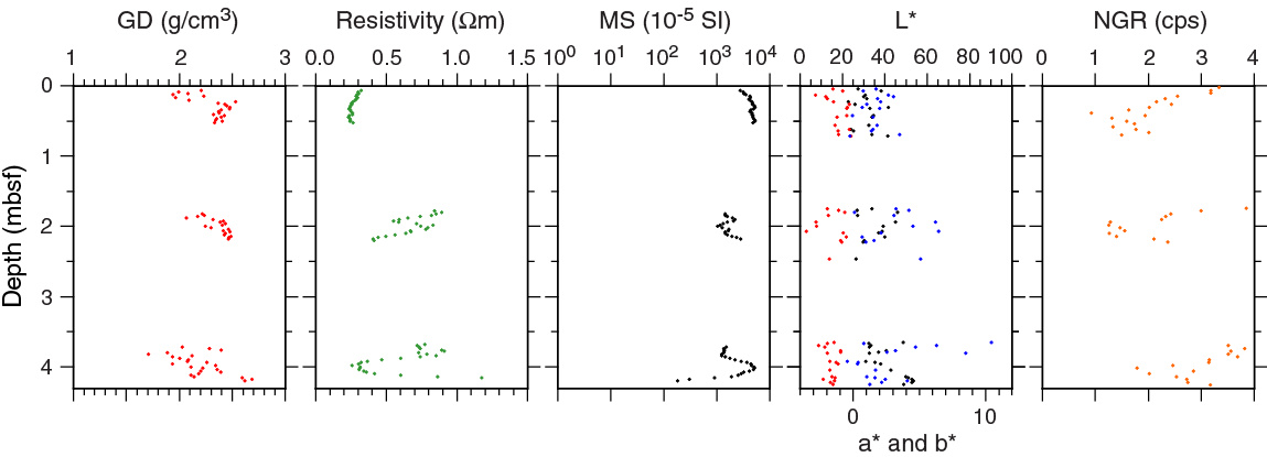
Figure F18. Physical properties, Hole M0071B.
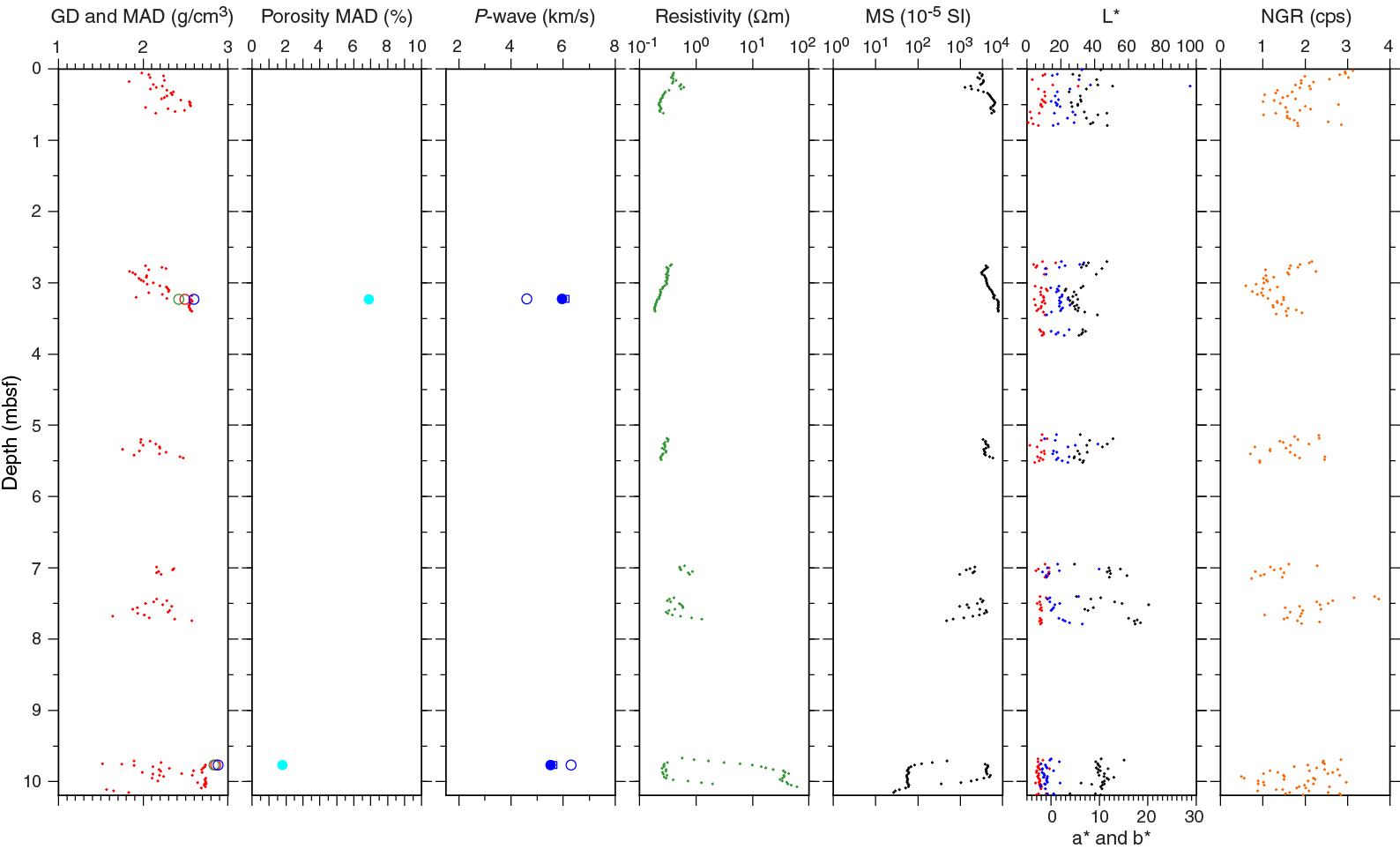
Figure F19. Physical properties, Hole M0071C.
Table T11. Grain density, porosity, and P-wave velocities for discrete samples, Site M0071. Download table in .csv format.
P-wave velocity
The four cylinder samples were also analyzed for triaxial P-wave velocity (Table T11). The serpentinized dunite (Sample 357-M0071A-1R-2, 122.0–124.0 cm) has an x-direction (horizontal) P-wave velocity of 4.75 km/s. The second horizontal direction, the y-direction, has a higher P-wave velocity (6.27 km/s). P-wave velocity measured along the z-direction (vertical) is 6.25 km/s. The mean P-wave velocity for this sample is 5.76 km/s. Sample 2R-1, 58.0–60.0 cm, a metagabbro, has an x-direction velocity of 5.60 km/s. The y-direction velocity is 5.10 km/s, and the z-direction velocity is 5.28 km/s. This sample has a mean velocity of 5.33 km/s. The serpentinized harzburgite sample (357-M0071C-2R-1, 54.5–57.5 cm) has an x-direction velocity of 4.60 km/s, a y-direction velocity of 5.95 km/s, and a z-direction velocity of 6.10 km/s. The mean is 5.55 km/s. The metadolerite sample (6R-1, 14.0–16.0 cm) has an x-direction velocity of 6.29 km/s, a y-direction velocity of 5.52 km/s, and a z-direction velocity of 5.62 km/s. The mean is 5.81 km/s.
Electrical resistivity
The mean electrical resistivity is 2.4 Ωm (Table T10). In most cores, resistivity is exceptionally low, with 88% of all measurements below 1 Ωm and 94% below 10 Ωm (Figures F17, F18, F19). Resistivity across Site M0071 ranges from 0.2 to 61.1 Ωm. At the base of Hole M0071A (3.3 mbsf), where the lithology changes from serpentinized lithologies to metagabbro, electrical resistivity reaches 7.7 Ωm.
Magnetic susceptibility
Magnetic susceptibility (MS) ranges between 27 × 10–5 and 8021 × 10–5 SI with a mean of 3591 × 10–5 SI (Table T10; Figures F17, F18, F19). The high magnetic susceptibility is likely due to the presence of magnetite-bearing serpentinized material. Similar to some of the other sites, magnetic susceptibility is systematically anticorrelated with electrical resistivity.
Natural gamma radiation
The natural gamma radiation (NGR) of all cores was measured on whole rounds. Because of the mineralogical makeup of the rocks sampled, NGR is systematically low across this site (Figures F17, F18, F19). Hole M0071A exhibits a subtle net decrease in NGR intensity with depth, whereas the two other holes show no overall change. Absolute values are not presented here because the units are uncalibrated. This data set is complemented by the corresponding gamma ray in situ measurements acquired in Hole M0071C (see Downhole logging).
Color reflectance
Lightness (L*) ranges from 26.47% to 59.84% with a mean of 45.01% (Table T10; Figures F17, F18, F19). Mean values of a* and b* are –1.89 (range = –5.32 to 2.94) and 7.35 (range = –1.56 to 17.40), respectively. The standard deviation of the dimensions is higher in the shallower two cores. In Hole M0071B, L* varies between 22.85% and 53.54% with a mean of 36.44%. Mean values of a* and b* are −1.44 (range = –3.52 to –0.18) and 2.54 (range = –0.45 to 10.44), respectively. The mean of L* in Hole M0071C is 39.26%, and it varies between 22.50% and 71.83%. a* ranges from –5.78 to 5.58 (mean = –2.13), and b* varies between –2.26 and 28.67 (mean = 1.46). This large range in b* is due to the measurement point at 0.24 mbsf with a b* value of 28.67, indicating the yellowish color of an oxidized rubble piece.
Summary
Physical properties from the ≈10 m of core recovered from the three holes drilled in the western area were acquired during the expedition, including analyses on four discrete samples. The western area is characterized by dominantly high magnetic susceptibility values and typically very low resistivity (Figures F17, F18, F19). Mean density values are skewed by poor core quality, returning lower than actual density values in certain intervals at this site.
Significant excursions in magnetic susceptibility and gamma density at the base of Holes M0071A and M0071C correspond to the presence of metagabbroic material (see Lithology, alteration, and structure). In these intervals, magnetic susceptibility drops off, suggesting a lower proportion of magnetic minerals where density increases, which is also consistent with the observed lithologic change (from lower density serpentinized lithologies to denser metagabbro). Metagabbro also exhibits more consistent color reflectance properties than the overlying lithologies.
The serpentinized dunite (see Lithology, alteration, and structure) at the top of Hole M0071A is distinct from all other lithologies reported at this site in that it has exceptionally high b*, reflecting the dominance of yellow chromaticity.
A crossplot of porosity and density from MAD analyses undertaken on four samples illustrates the differences in the physical properties of some of the lithologies encountered in the western area. The serpentinized samples (referred to as serpentinites in Figure F20) have similarly low grain densities and high porosities relative to the metagabbro and metadolerite samples. The metadolerite is the densest and least porous of all of the samples analyzed. The vertical P-wave velocities of the serpentinite samples are higher than those of the mafic rocks. One of the horizontal directions (y) is higher in the serpentinized samples as well; the other (x) is lower. Comparison of acoustic velocities in the x-, y-, and z-directions within individual samples suggests that the serpentinized samples may be more anisotropic than the two mafic samples.
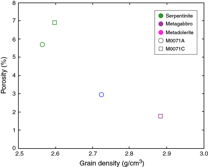
Figure F20. Grain density and porosity data from MAD analyses, Site M0071.
Downhole logging
A ≈11 m interval of Hole M0071C was logged through the drill string using the SGR sonde (see Downhole logging in the Expedition 357 methods chapter [Früh-Green et al., 2017b]) over a period of approximately 2 h. A technical failure with the MeBo following termination of the hole due to difficult drilling conditions dictated that open-hole logging operations with the DIL in this hole be aborted, and ultimately the hole was abandoned with the drill string left in the hole.
Operations
Downhole logging operations in Hole M0071C commenced at 0058 h local time on 28 November 2015 after coring was terminated because of difficult drilling conditions. The total depth of the hole was 12.1 mbsf. The logging plan was to first deploy the SGR through-pipe via the winch for acquisition of total gamma ray measurements, followed by open-hole logging with the DIL while the drill string was recovered to the MeBo.
The SGR was collected from its magazine and positioned over the drill string using the chuck. The chuck was then lowered until the SGR was in the drill string. At this point, the chuck was opened to allow the SGR to free fall to the bottom of the drill string. For through-pipe measurements it is necessary to undertake logging because the tool is recovered to the MeBo using a cable. An overshot connected to the winch cable was therefore deployed to retrieve the SGR from the bottom of the hole. An initial uplog of the hole was undertaken with the SGR at a speed of ≈180 m/h and a maximum logged depth of 11.1 mbsf (Figure F21). This uplog was followed by a repeat pass from the bottom of the drill string. The SGR was then removed from the drill string and returned to its magazine.

Figure F21. Geometry of logging from the MeBo, Hole M0071C.
In anticipation of undertaking open-hole logging operations, one length of drill pipe was removed from the drill string and the DIL was collected from its magazine. However, once in position for free falling the tool inside the drill string, the chuck was unable to release the tool. This failure in the drill meant that the attempt at open-hole logging had to be terminated, and the tool was subsequently replaced in its magazine. Logging operations were concluded at 0151 h on 28 November.
Data processing and quality assessment
Very low gamma counts from the formations penetrated in Hole M0071C, in combination with the attenuation of the gamma signal by the drill pipe, make it impossible to discern the seafloor from the gamma profile. Depth may also be referenced to the amount of cable payed out by the winch, but the MeBo’s winch is not equipped with a depth encoder, and an accurate record of spooled cable was consequently not available. The references utilized here for depth are therefore the bit depth and the height of the wellhead. Because the MeBo is a stable platform not affected by tides, currents, or ship’s heave while on the seafloor, these reference points are adequate for positioning the downhole logs in vertical space, assuming a constant winch haul rate. The repeat uplog of the SGR was used as the reference log to which the initial uplog was matched based on the identification of common features. This ensured consistency across the data sets, and the two sets provide a means of assessing the repeatability of the measurements.
Centralization of the SGR in the drill string is very effective and optimizes data quality. Hole condition affects the quality of downhole measurements, but because we made no open-hole measurements, it is impossible to comment on the profile of the borehole. Changes in the log with depth that are a consequence of borehole diameter rather than the formation itself therefore cannot be identified or quantified.
Logging stratigraphy
The logged interval in Hole M0071C is not divided into discrete logging units because the intensity of the natural gamma ray signal is consistently low and the character of the downhole profile is relatively constant.
Logging Unit 1 (0–11 mbsf) is characterized by very low gamma radiation ranging from 1.7 to 8.2 American Petroleum Institute gamma radiation units (gAPI) with a mean of 5.9 gAPI (Figure F22). There is a net increase in gamma ray downhole to the maximum intensity at ≈7.2 mbsf. Below this point, gamma ray decreases overall to the base of the hole. This drop in values is particularly evident from 10 mbsf to the base of the hole.

Figure F22. Total gamma ray downhole logging measurements through-pipe and core data, Hole M0071C.
Core-log correlations
A complementary NGR data set was acquired from the WRCs (see Physical properties). The principle of the two measurements is essentially the same (see Downhole logging and Physical properties, both in the Expedition 357 methods chapter [Früh-Green et al., 2017b]), but different sample volumes and the geological heterogeneity of Atlantis Massif make it difficult to compare these data sets. Core data are also difficult to integrate with the continuous downhole logging data because of limited core recovery in this hole. However, the decreasing trend in gamma ray at the base of the hole is present in both the core and log data sets (Figure F22).
Paleomagnetism
To achieve the main paleomagnetic objectives, magnetic susceptibility measurements (κ) and rudimentary analyses of natural remanent magnetization (NRM) were made on discrete specimens of known volume and mass (see Paleomagnetism in the Expedition 357 methods chapter [Früh-Green et al., 2017b]). A total of four discrete samples were collected from Holes M0071A (three samples) and M0071C (one sample). Samples were taken at irregular intervals, governed by lithology and coherency of core material. The magnetic susceptibility in these samples ranges from 0.00031 to 0.07780 SI units (Table T12). The samples with the lowest susceptibility values correspond to metagabbro (Sample 357-M0071A-2R-1, 54 cm) and metadolerite (Sample 357-M0071C-6R-1, 16.5 cm), and the highest value corresponds to serpentinized harzburgite (Sample 357-M0071A-1R-CC, 1.5 cm). These susceptibility results suggest that changes in magnetic mineralogy and/or magnetic grain size may be driving the κ results, but this requires further verification.
Table T12. Magnetic susceptibility and NRM inclinations of discrete samples, Site M0071. Download table in .csv format.
The NRM direction and intensity of the discrete samples were measured using the 2G-Enterprises SRM 755–4000 magnetometer (see Paleomagnetism in the Expedition 357 methods chapter [Früh-Green et al., 2017b]). Results indicate that an alternating field (AF) of 5–20 mT is sufficient to remove a weak viscous remanent magnetization (VRM) for all samples from the western sites. The responses to the sequential AF demagnetization displayed by the samples from Holes M0071A and M0071C showed similar trends with two main groups. Two samples lost 50% of their NRM intensity at alternating fields less than 10 to 15 mT (i.e., Samples 357-M0071A-1R-1, 21 cm, and 1R-CC, 1.5 cm) (Figure F23). The other samples lost 50% of the magnetization below 40 mT. All specimens yielded vector diagrams that smoothly demagnetize up to the maximum AF demagnetization level of 100 mT, with a vector that trends univectorially toward the origin of the orthogonal projection. This magnetic behavior indicates that a characteristic remanent magnetization (ChRM) was successfully isolated, and inclination values were determined.

Figure F23. Typical AF progressive demagnetization, Site M0071.
Inclination values from Hole M0071A are positive and range from 39° to 57.7°. The one sample from Hole M0071C is characterized by a negative inclination (–56.9°) (Table T12). These inclination values are not in agreement with the expected geocentric axial dipole inclination (–49°) for the location of the sampling site, which is consistent with the fact that drilling at Site M0071 appears to have gone through large rubble blocks. Thus, these samples cannot be used for relative dating purposes.
References
Blackman, D.K., Karson, J.A., Kelley, D.S., Cann, J.R., Früh-Green, G.L., Gee, J.S., Hurst, S.D., John, B.E., Morgan, J., Nooner, S.L., Ross, D.K., Schroeder, T.J., and Williams, E.A., 2002. Geology of the Atlantis Massif (Mid-Atlantic Ridge, 30°N): implications for the evolution of an ultramafic oceanic core complex. Marine Geophysical Research, 23(5–6):443–469. http://dx.doi.org/10.1023/B:MARI.0000018232.14085.75
Früh-Green, G.L., Orcutt, B.N., Green, S.L., Cotterill, C., Morgan, S., Akizawa, N., Bayrakci, G., Behrmann, J.-H., Boschi, C., Brazelton, W.J., Cannat, M., Dunkel, K.G., Escartin, J., Harris, M., Herrero-Bervera, E., Hesse, K., John, B.E., Lang, S.Q., Lilley, M.D., Liu, H.-Q., Mayhew, L.E., McCaig, A.M., Menez, B., Morono, Y., Quéméneur, M., Rouméjon, S., Sandaruwan Ratnayake, A., Schrenk, M.O., Schwarzenbach, E.M., Twing, K.I., Weis, D., Whattam, S.A., Williams, M., and Zhao, R., 2017a. Eastern sites. In Früh-Green, G.L., Orcutt, B.N., Green, S.L., Cotterill, C., and the Expedition 357 Scientists, Atlantis Massif Serpentinization and Life. Proceedings of the International Ocean Discovery Program, 357: College Station, TX (International Ocean Discovery Program). http://dx.doi.org/10.14379/iodp.proc.357.103.2017
Früh-Green, G.L., Orcutt, B.N., Green, S.L., Cotterill, C., Morgan, S., Akizawa, N., Bayrakci, G., Behrmann, J.-H., Boschi, C., Brazelton, W.J., Cannat, M., Dunkel, K.G., Escartin, J., Harris, M., Herrero-Bervera, E., Hesse, K., John, B.E., Lang, S.Q., Lilley, M.D., Liu, H.-Q., Mayhew, L.E., McCaig, A.M., Menez, B., Morono, Y., Quéméneur, M., Rouméjon, S., Sandaruwan Ratnayake, A., Schrenk, M.O., Schwarzenbach, E.M., Twing, K.I., Weis, D., Whattam, S.A., Williams, M., and Zhao, R., 2017b. Expedition 357 methods. In Früh-Green, G.L., Orcutt, B.N., Green, S.L., Cotterill, C., and the Expedition 357 Scientists, Atlantis Massif Serpentinization and Life. Proceedings of the International Ocean Discovery Program, 357: College Station, TX (International Ocean Discovery Program). http://dx.doi.org/10.14379/iodp.proc.357.102.2017
Früh-Green, G.L., Orcutt, B.N., Green, S.L., Cotterill, C., Morgan, S., Akizawa, N., Bayrakci, G., Behrmann, J.-H., Boschi, C., Brazelton, W.J., Cannat, M., Dunkel, K.G., Escartin, J., Harris, M., Herrero-Bervera, E., Hesse, K., John, B.E., Lang, S.Q., Lilley, M.D., Liu, H.-Q., Mayhew, L.E., McCaig, A.M., Menez, B., Morono, Y., Quéméneur, M., Rouméjon, S., Sandaruwan Ratnayake, A., Schrenk, M.O., Schwarzenbach, E.M., Twing, K.I., Weis, D., Whattam, S.A., Williams, M., and Zhao, R., 2017c. Expedition 357 summary. In Früh-Green, G.L., Orcutt, B.N., Green, S.L., Cotterill, C., and the Expedition 357 Scientists, Atlantis Massif Serpentinization and Life. Proceedings of the International Ocean Discovery Program, 357: College Station, TX (International Ocean Discovery Program). http://dx.doi.org/10.14379/iodp.proc.357.101.2017
McDonough, W.F., and Sun, S.-S., 1995. The composition of the Earth. Chemical Geology, 120(3–4):223–253. http://dx.doi.org/10.1016/0009-2541(94)00140-4
Sun, S.-S., and McDonough, W.F., 1989. Chemical and isotopic systematics of oceanic basalts: implications for mantle composition and processes. In Saunders, A.D., and Norry, M.J. (Eds.), Magmatism in the Ocean Basins. Geological Society Special Publication, 42:313–345. http://dx.doi.org/10.1144/GSL.SP.1989.042.01.19
1 Früh-Green, G.L., Orcutt, B.N., Green, S.L., Cotterill, C., Morgan, S., Akizawa, N., Bayrakci, G., Behrmann, J.-H., Boschi, C., Brazelton, W.J., Cannat, M., Dunkel, K.G., Escartin, J., Harris, M., Herrero-Bervera, E., Hesse, K., John, B.E., Lang, S.Q., Lilley, M.D., Liu, H.-Q., Mayhew, L.E., McCaig, A.M., Menez, B., Morono, Y., Quéméneur, M., Rouméjon, S., Sandaruwan Ratnayake, A., Schrenk, M.O., Schwarzenbach, E.M., Twing, K.I., Weis, D., Whattam, S.A., Williams, M., and Zhao, R., 2017. Western sites. In Früh-Green, G.L., Orcutt, B.N., Green, S.L., Cotterill, C., and the Expedition 357 Scientists, Atlantis Massif Serpentinization and Life. Proceedings of the International Ocean Discovery Program, 357: College Station, TX (International Ocean Discovery Program). http://dx.doi.org/10.14379/iodp.proc.357.105.2017
- F1. DSL120 sonar imagery and 50 m resolution multibeam bathymetry, Sites M0071 and M0073.
- F2. Location of Holes M0071A–M0071C.
- F3. Core recovery and lithology, Site M0071.
- F4. Serpentinized harzburgite with vermicular chromian spinel.
- F5. Alteration, Hole M0071A.
- F6. Alteration, Hole M0071C.
- F7. Fully serpentinized dunite with serpentine mesh texture overprinted by carbonate veins with associated oxidation halos.
- F8. Mineralogical assemblages within rubble pieces, Site M0071.
- F9. Mineral phases identified by bulk powder XRD analysis, Site M0071.
- F10. PM–normalized extended trace element plot, Site M0071.
- F11. Chondrite-normalized REE plot, Site M0071.
- F12. Sensor data, Hole M0071A.
- F13. Sensor data, Hole M0071B.
- F14. Sensor data, Hole M0071C.
- F15. Borehole plug emplacement, Hole M0071B.
- F16. Equipment left behind in borehole, Hole M0071C.
- F17. Physical properties, Hole M0071A.
- F18. Physical properties, Hole M0071B.
- F19. Physical properties, Hole M0071C.
- F20. Grain density and porosity data from MAD analyses, Site M0071.
- F21. Geometry of logging from the MeBo, Hole M0071C.
- F22. Total gamma ray downhole logging measurements through-pipe and core data, Hole M0071C.
- F23. Typical AF progressive demagnetization, Site M0071.
- T1. Western sites hole summary.
- T2. X-ray diffraction results, Site M0071.
- T3. Whole-round cores collected for microbiological analysis, Site M0071.
- T4. Core liner fluid samples for microbiological analyses, Site M0071.
- T5. Water samples collected from sensor package Niskin bottles for microbiological analysis, Site M0071.
- T6. Water samples collected from CTD rosette Niskin bottles for microbiological analysis, Site M0071.
- T7. Sensor signal time log, Hole M0071A.
- T8. Sensor signal time log, Hole M0071B.
- T9. Sensor signal time log, Hole M0071C.
- T10. Physical properties, Site M0071.
- T11. Grain density, porosity, and P-wave velocities for discrete samples, Site M0071.
- T12. Magnetic susceptibility and NRM inclinations of discrete samples, Site M0071.