MacLeod, C.J., Dick, H.J.B., Blum, P., and the Expedition 360 Scientists
Proceedings of the International Ocean Discovery Program Volume 360
publications.iodp.org
doi:10.14379/iodp.proc.360.104.2017

Hole 1105A redescription1
C.J. MacLeod, H.J.B. Dick, P. Blum, N. Abe, D.K. Blackman, J.A. Bowles, M.J. Cheadle, K. Cho, J. Ciążela, J.R. Deans, V.P. Edgcomb, C. Ferrando, L. France, B. Ghosh, B.M. Ildefonse, M.A. Kendrick, J.H. Koepke, J.A.M. Leong, C. Liu, Q. Ma, T. Morishita, A. Morris, J.H. Natland, T. Nozaka, O. Pluemper, A. Sanfilippo, J.B. Sylvan, M.A. Tivey, R. Tribuzio, and L.G.F. Viegas2
Keywords: International Ocean Discovery Program, IODP, JOIDES Resolution, Expedition 360, Hole 1105A, Moho, Mohorovičić discontinuity, Southwest Indian Ridge, SloMo, Atlantis Bank, mid-ocean ridge, slow spreading rate, Atlantis II Transform
MS 360-104: Published 30 January 2017
Background and objectives
During the 11 day transit from Colombo, Sri Lanka, to International Ocean Discovery Program (IODP) Site U1473 at Atlantis Bank, the Expedition 360 science party reexamined cores drilled during Ocean Drilling Program (ODP) Leg 179 in Hole 1105A (Pettigrew, Casey, Miller, et al., 1999; Casey et al., 2007). This activity involved rigorously describing the cores and many of the accompanying thin sections with the primary purpose of familiarizing the science party with the material likely to be encountered at the new Site U1473, situated 1.4 km to the north. The science party developed templates for description of the igneous, metamorphic, and structural features of the cores and analyzed thin sections made during Leg 179 to establish core description protocols for the new Site U1473 cores. An additional benefit of redescribing Hole 1105A cores is that the data generated are in a format directly comparable with those for Hole U1473A.
In general, our findings were very similar to those produced by the Leg 179 scientists; however, with a larger science party to work on the cores, some of the information collected is new. We include this information in this chapter, as a basis for direct comparison with the results of drilling at Site U1473. In addition, we were able to make certain physical properties measurements on Hole 1105A cores, including magnetic susceptibility measurements of core section halves, that had not been possible during Leg 179. It is important to note here that the observations made on Hole 1105A cores by the Expedition 360 science party augment rather than replace those made by the Leg 179 scientists.
Igneous petrology
During the transit to Atlantis Bank we redescribed cores from Hole 1105A that were recovered during Leg 179. Our observations on the igneous petrology of this section are summarized below and then briefly compared with those made during Leg 179. Leg 179 recovered 30 cores in Hole 1105A (0–157.43 meters below seafloor [mbsf]; recovery = 123 m; 78.1% recovery) composed of gabbroic rocks and related felsic veins (Pettigrew, Casey, Miller, et al., 1999; Casey et al., 2007) (Figure F1A). The gabbroic rocks are mostly coarse grained with subophitic to granular textures and are variably deformed. Subophitic textures dominate in undeformed samples. The main lithologies are oxide gabbro and olivine gabbro, followed in abundance by gabbro (sensu stricto). A significant portion of olivine gabbro and gabbro contain small amounts of oxides and are referred to as disseminated-oxide gabbro (1%–2% oxides) and oxide-bearing gabbro (2%–5% oxides). As a whole, gabbroic rocks with oxides >1% dominate deeper than 35 m core composite depth below seafloor (CCSF) and are more plastically deformed than other lithologies. Oxides are particularly abundant and probably crystallized from percolating evolved melts. In these deformed gabbros, oxides are not affected by plastic deformation and thus apparently crystallized after dynamic recrystallization of the silicates. Some rare undeformed oxide gabbros are also observed. Thin intrusions of fine-grained olivine gabbro occur between 60 and 75 m CCSF. Numerous felsic veins occur throughout the core and are concentrated between 15 and 60 m CCSF and between 135 and 155 m CCSF. Detailed observations of the corresponding thin sections allow us to document the evolution of late-stage melts within a crystallizing mush and to track the origin of magmatic oxide minerals where they are particularly enriched.
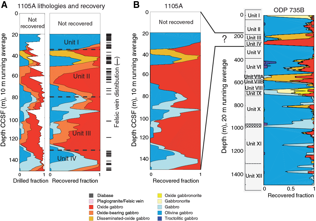
Figure F1. A. Lithostratigraphic variations in Hole 1105A as redescribed during Expedition 360. B. Hole 1105A compared to Hole 735B.
When compared with ODP Hole 735B gabbro, Hole 1105A is more enriched in oxide-bearing varieties (disseminated-oxide gabbro, oxide-bearing gabbro, and oxide gabbro) and therefore represents a section of crust that is more evolved overall than that recovered in Hole 735B (Figure F1B). The oxide-rich section of Hole 1105A is thicker overall and more enriched in oxides than the principal oxide-rich portions of Hole 735B (Units III and IV). Deformation grade and alteration patterns are also different, and a downhole differentiation trend similar to the one observed for Hole 735B oxide gabbro is questionable for Hole 1105A whole-rock compositions but may be more evident when considering mineral compositions (Dick, Natland, Miller, et al., 1999; Pettigrew, Casey, Miller, et al., 1999; Casey et al., 2007). If the Hole 1105A section is equivalent to any section in Hole 735B, it would have to be Units III and IV (Casey et al., 2007); nevertheless, given the mismatching comparisons presented above and as discussed in Casey et al. (2007), Hole 1105A may not represent a section that correlates directly with Hole 735B. Rather, it may record a single process led by the percolation of evolved melts (that have the potential to fractionate oxides) in high-porosity regions located in the shallowest levels of the holes. In Hole 735B, this porosity level clearly corresponds to units affected by crystal-plastic deformation; such a relation is less evident in Hole 1105A. The shallowest section of Hole 1105A (from 15 to 40 m CCSF) is composed of less evolved (olivine gabbro) and less deformed material than in the deeper sections and is similar to several units recovered lower in Hole 735B (Figure F1B). In Hole 735B, most felsic veins are associated with oxide gabbro (e.g., Natland et al., 1991), a relationship that is not observed in Hole 1105A.
When compared with results of Leg 179 (Pettigrew, Casey, Miller, et al., 1999), we defined fewer intervals (108 during Expedition 360 versus 141 during Leg 179). The Leg 179 modal content estimates are on average also quite different from ours. Thus, the proportions of rock types described are significantly different as well: olivine gabbro (38.5% during Expedition 360 versus 43% during Leg 179), gabbro (21% versus 36%, respectively), and oxide gabbro (40.5% versus 21%, respectively). For the comparison above, we combined disseminated-oxide (1%–2% oxide) and oxide-bearing (2%–5% oxide) gabbro with gabbro (<1% oxide), as these three lithologies were all described as gabbro by the Leg 179 scientists.
The units defined during Leg 179 and Expedition 360 are relatively similar to each other. Four units were defined during Leg 179 (two subunits in Unit II) and during Expedition 360. The transition between Units I and II are relatively close (<10 m difference), the transition between Subunits IIA and IIB of Leg 179 and between Units II and III of Expedition 360 also differ by <10 m, and the transition between Subunit IIB and Unit III of Leg 179 is 4 m deeper than the transition between Units III and IV of Expedition 360. No distinction was made during Expedition 360 for the deepest part of Hole 1105A where Unit IV was defined during Leg 179.
Lithostratigraphy
Major rock types
A variety of gabbroic rocks were identified in the Hole 1105A cores based on visual estimates and thin section observations (Table T1). These included olivine gabbro (27.2 vol%), gabbro (13.4 vol%), disseminated-oxide gabbro (3 vol%), oxide-bearing gabbro (15.4 vol%), and oxide gabbro (40.0 vol%). In addition, felsic rocks, consisting mainly of plagioclase and amphibole, are present as veins crosscutting the cores (~1 vol%). As a whole, oxide gabbro families (disseminated-oxide, oxide-bearing, and oxide gabbro) are the dominant rock types, constituting >59 vol% of the cores.
Table T1. Summary of lithology thickness and proportion, Hole 1105A. Download table in .csv format.
Many of the gabbroic rocks display deformation textures ranging from weakly deformed to porphyroclastic and mylonitic. These aspects are treated in detail in Structural geology. Where possible, the original igneous texture and composition were inferred based on porphyroclasts.
Lithologic units
We recognized four major lithologic units in the cores recovered during Leg 179 (Hole 1105A); the different units were determined based on their modal and grain size variations (Table T2):
- Unit I: olivine gabbro (Intervals 1–11; 0–37.39 m CCSF). Unit I consists mostly of coarse-grained subophitic olivine gabbro with numerous felsic veins.
- Unit II: oxide gabbro (Intervals 12–44; 37.39–81.8 m CCSF). Unit II consists mostly of coarse-grained subophitic oxide gabbro with rare felsic veins.
- Unit III: oxide gabbro (Intervals 45–93; 81.8–132.37 m CCSF). Unit III consists mostly of coarse-grained granular oxide gabbro with very rare felsic veins. The oxide concentration is slightly lower than in Unit II.
- Unit IV: gabbro and olivine gabbro (Intervals 94–108; 132.37–157.43 m CCSF). Unit IV consists mostly of coarse-grained subophitic gabbro and olivine gabbro with numerous felsic veins.
Table T2. Primary igneous lithologies (intervals), Hole 1105A. Download table in .csv format.
The depth distribution of rock types and unit boundaries are presented in Figure F1.
Core descriptions
Modal variations
Modal abundances of the primary magmatic phases were estimated visually and when possible checked in thin section. Pseudomorphs of magmatic phases replaced by secondary minerals were also included in the estimate. Where amphibole occurs together with plagioclase in felsic veins, the amphibole is secondary (metamorphic) and replaces both clinopyroxene and magmatic amphibole. It has thus been counted as magmatic amphibole for estimates of the modal composition. The proportions of major silicate phases in different rock types are reported in Figure F2 and Table T2. Modal proportions do not show any clear trend with depth, although the olivine mode slightly decreases from the top to the bottom of the hole. The modal compositions of plagioclase and clinopyroxene are highly variable in the upper 100 m of Hole 1105A but are more uniform in the deepest part. The modes of plagioclase and clinopyroxene generally vary in sympathetic fashion, with one exception at ~75 m CCSF, which is represented by various fine-grained plagioclase-rich olivine gabbro intervals. These form layers within coarser-grained olivine gabbros and could be interpreted as (i) heterogeneous patches in varitextured gabbros, (ii) igneous layering transposed by deformation, or (iii) melt percolation channels formed through melt-porous flow. None of these possibilities seem to be excluded, although the weak deformation and the irregular contacts seem to suggest that they are the results of dissolution of the hosting gabbros by a melt migrating upward by porous flow.
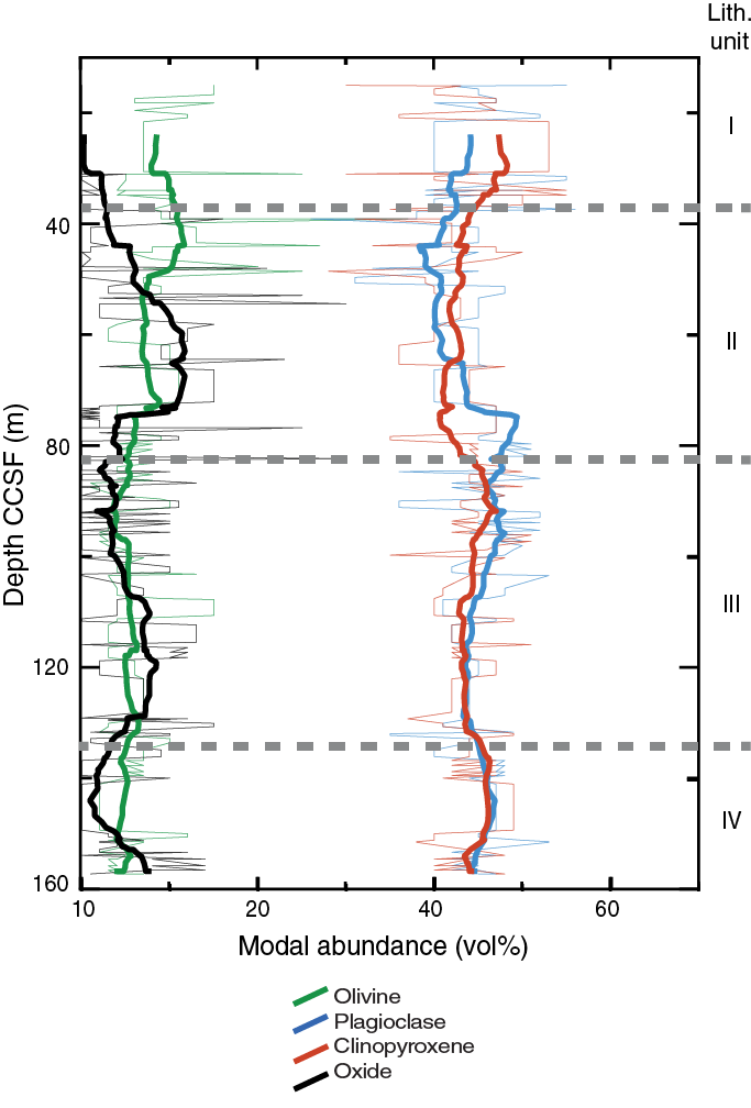
Figure F2. Variations of mineral mode with depth plotted by interval, Hole 1105A.
The average phase proportions in weight percent (calculated from volume percents using mineral densities) of the fine-grained olivine gabbro layers (olivine:plagioclase:clinopyroxene = 9:64:27) are in relatively good agreement with the cotectic proportions during low-pressure crystallization experiments (11:59:30; Grove et al., 1992). In contrast, coarse-grained olivine gabbro and gabbro have average phase proportions different from those of low-pressure crystallization experiments on mid-ocean-ridge basalt (MORB) (Grove et al., 1992). In particular, the olivine:plagioclase:clinopyroxene ratio of the olivine gabbro (10:41:49) is more enriched in clinopyroxene with respect to the cotectic proportions in those low-pressure experiments. Orthopyroxene occurs exclusively within the oxide-poor samples, where it never exceeds 3 vol%. The oxide-bearing gabbro and oxide gabbro have olivine:plagioclase:clinopyroxene proportions similar to the olivine gabbro (7:41:52). However, when considering only the oxide-rich samples (oxide modal content >10 vol%), the plagioclase modal composition decreases significantly at increasing oxide content (Figure F3). This suggests that the addition of oxides in these rocks is at the expense of the felsic phases.

Figure F3. Correlations between plagioclase and oxide modes, Hole 1105A.
Interestingly, the modal proportion of the olivine and oxide gabbros from Hole 1105A differs slightly from that of Hole 735B, which has olivine:plagioclase:clinopyroxene proportions in good agreement with cotectic proportions obtained by crystallization experiments (see Bloomer et al., 1991). We suggest that the Hole 1105A olivine gabbros contain excess clinopyroxene, probably related to the higher amount of oxide gabbros in this hole (40.5 vol%) than in Hole 735B (8 vol%).
Contacts
In this section, we review the nature of the contacts between individual intervals defined from the visual inspection of the cores. We emphasize the primary igneous aspects, whereas the deformational and structural aspects will be described in Structural geology. The intervals were defined visually based on differences in lithology (modal content and grain size) and physical aspects (intrusive or sheared). When not recovered, contacts were documented as “not recorded.” Simple intrusive contacts, such as most dike/gabbro contacts, are characterized by a sharp discontinuity that cuts across grain boundaries, whereas sutured contacts where grains are not broken but interlock represent a discontinuity in grain size or phase proportions. These latter types of contacts characterize those between fine-grained gabbro (olivine to oxide gabbro) and medium- to coarse-grained gabbro and occur in numerous places throughout Hole 1105A (e.g., Figures F4, F5). Sheared contacts are those where an original igneous contact is extensively modified by deformation. Sheared contacts are either very sharp or irregular and are characterized by the development of foliated and mylonitic fabrics. Sheared contacts locally show grain size decreasing toward the contact. Such intervals occur most clearly at 17 m CCSF and between 73 and 75 m CCSF, where the contacts are locally overprinted by a later crystal-plastic fabric (CPF).

Figure F4. Boundary between olivine-bearing oxide gabbro and olivine-bearing gabbro, Hole 1105A.
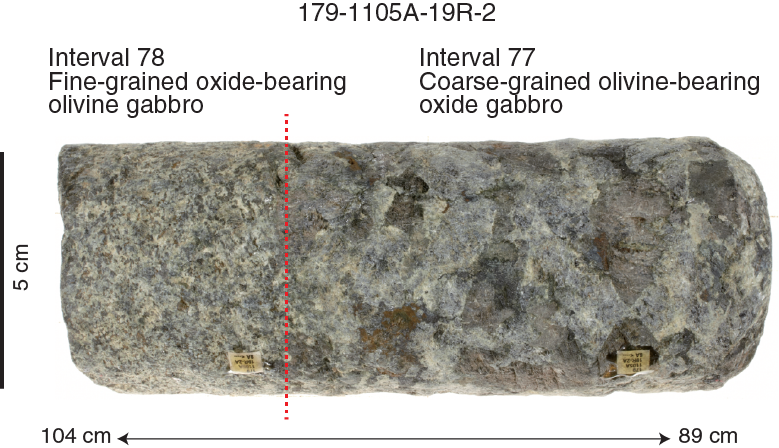
Figure F5. Boundary between coarse-grained olivine-bearing oxide gabbro and fine-grained oxide-bearing olivine gabbro, Hole 1105A.
Of the 221 breaks in lithology, the origin of 35% are unknown due to poor recovery, 31% of the recovered contacts were classified as modal, 20% as grain size, and only 9% and 6% as intrusive and sheared, respectively. The majority of the contacts resemble cumuluslike layering and are planar, recognized on the basis of relatively abrupt changes in either grain size or modal composition, and we note that felsic veins also have intrusive contacts, although they were too small to be defined as individual intervals and are described separately. Although there is no correlation between types of contacts and depth, most unrecovered contacts were concentrated in the lower half of the hole (Figure F6).
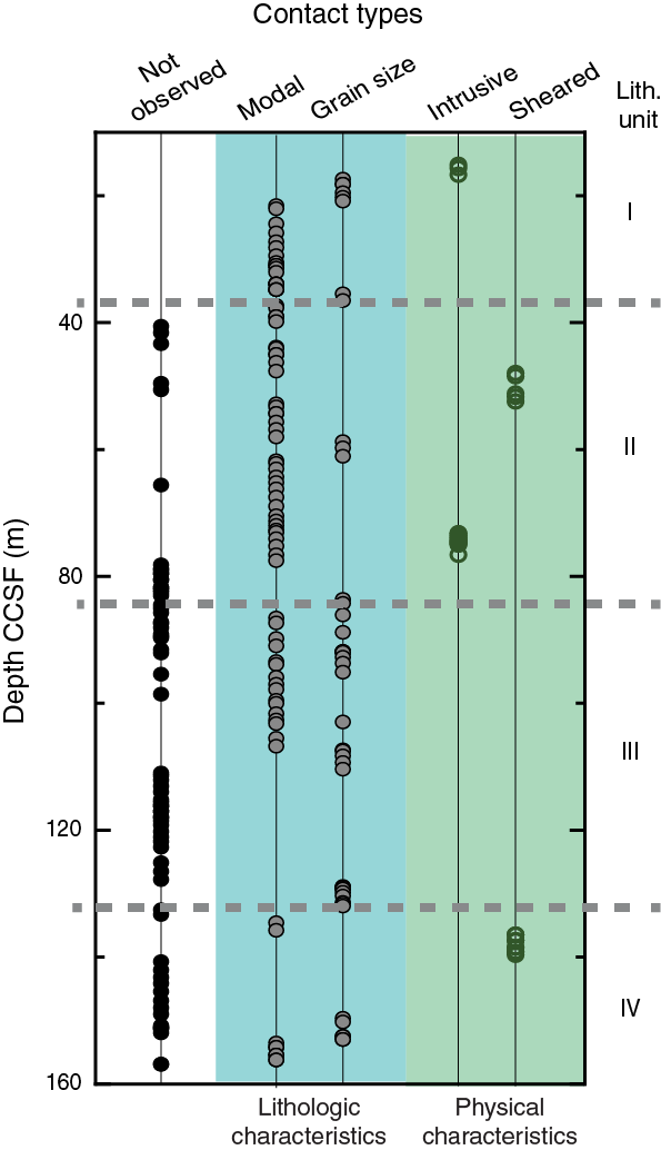
Figure F6. Variations in contact type with depth, Hole 1105A.
Grain size variations
The minimum, maximum, and mean grain sizes of each major constituent mineral (olivine, plagioclase, clinopyroxene, and orthopyroxene) in each lithologic interval were estimated in hand specimen along the long axis of each mineral (Figures F7, F8). Average grain size of samples varies from fine grained (<1 mm) to pegmatitic (>30 mm) over length scales of centimeters to meters. Average grain size is generally in the range of coarse (5–15 mm) to very coarse (15–30 mm). The most general features observed in hand specimen are (1) all phases increase in grain size as overall mean increases and (2) as overall grain size increases, clinopyroxene size increase is relatively bigger than plagioclase, which size increase is relatively bigger than olivine. These correlations are independent of the rock type. Clinopyroxene is relatively coarser than plagioclase for grains >10 mm; olivine is generally <10 mm (Figure F8). Related to this, very coarse grained gabbro and some pegmatitic gabbro intervals have ophitic texture, with clinopyroxene oikocrysts enclosing mainly plagioclase.
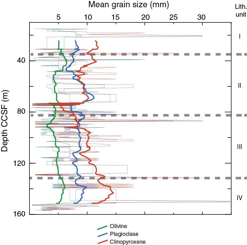
Figure F7. Variations in mean grain sizes of plagioclase, clinopyroxene, and olivine with depth plotted by interval, Hole 1105A.
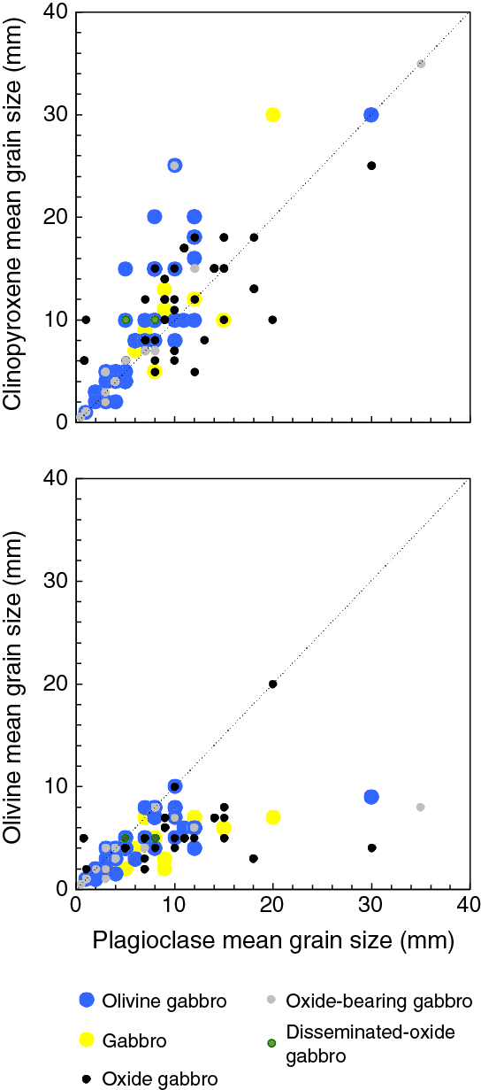
Figure F8. Correlations of mean grain size between plagioclase and clinopyroxene and olivine, Hole 1105A.
Thin pegmatitic intervals and thin fine-grained intervals tend to have abrupt contacts with the surrounding coarse-grained gabbro, and both types of intervals tend to occur in clusters. Peaks in average grain size occur at 20, 35, 85, 130, and 150 m CCSF where pegmatitic/very coarse grained gabbros occur (Figure F7). Olivine has a grain size spike at 39 m CCSF. Running average grain sizes over 10 intervals show a negative spike near 75 m CCSF where several fine-grained olivine gabbros intrude gabbros.
Textures
Olivine gabbro and gabbro
Olivine gabbro (>5% modal olivine) and gabbro (<5% modal olivine) are the dominant rock types distributed throughout lithologic Unit I. The primary modal mineralogy estimated visually from the cores consists of olivine (4–25 vol%), plagioclase (39–56 vol%), and clinopyroxene (30–55 vol%) with traces of orthopyroxene (3 vol%, found in one sample) and minor Fe-Ti oxides and sulfides. These rocks are mostly medium to coarse grained (Figure F9A–F9B), but in many cases the minerals have a pegmatitic habit. Plagioclase commonly occurs as elongate euhedral to subhedral grains in coarse-grained and pegmatitic rocks, whereas it is mostly subhedral and lath shaped in medium-grained rocks. Clinopyroxene mostly occurs as subhedral subequant crystals in coarse- to medium-grained rocks but commonly occurs as prismatic to equant euhedral grains in the pegmatitic variants. Olivine is rounded and subhedral to anhedral, commonly included in plagioclase and, to some extent, in clinopyroxene. Fe-Ti oxide minerals are generally <1 mm in grain size in gabbro and olivine gabbro and occur as disseminated grains.
Figure F9. Medium-grained olivine gabbro, coarse-grained olivine gabbro, and pegmatitic olivine gabbro, Hole 1105A.
Olivine gabbro displays subhedral granular textures with interlocking plagioclase and clinopyroxene crystals (Figure F9C), whereas the pegmatitic olivine gabbro has poikilitic or subophitic textures in which large subhedral clinopyroxene oikocrysts enclose or partly enclose relatively smaller subhedral elongate plagioclase and, to some extent, olivine crystals.
Oxide gabbro and oxide olivine gabbro
Oxide gabbro (>5% modal Fe-Ti oxide; <5% modal olivine) and oxide olivine gabbro (>5% modal Fe-Ti oxide; >5% modal olivine) are the principal rock types in lithologic Units II–III. The primary mineral assemblages and modal compositions of oxide gabbro and oxide olivine gabbro are generally olivine (1–37 vol%), plagioclase (10–60 vol%), clinopyroxene (10–51 vol%), and opaque minerals (Fe-Ti oxides and sulfides; 5–12 vol%). Oxide gabbro and oxide olivine gabbro are in many respects similar to the gabbro and olivine gabbro described above, especially in terms of rock textures and crystal morphologies. Nonetheless, there are some distinct differences between these groups of gabbroic rocks. In addition to (by definition) having higher modal Fe-Ti oxide contents, the oxide minerals present in rocks termed oxide gabbro and oxide olivine gabbro are generally larger (up to 10 mm) and are present not only as single, interstitial fillings between the larger silicates but also as elongate aggregates in the form of seams and bands.
Felsic veins
Figure F1 shows the location of felsic veins in the cores. Felsic veins are particularly concentrated in ranges <60 and >135 m CCSF, where they are generally more abundant away from the most oxide-rich parts of the section. These veins vary in width, geometry, and modal composition. Despite their small volume, felsic veins have important roles in the chemical budget of the section, particularly for incompatible trace elements and as indicators of physical processes occurring during crustal accretion.
The felsic veins vary in geometry from regular planar dikes/dikelets to irregularly shaped pockets and networks and vary in size/thickness from a few millimeters to several centimeters. Most of the veins are composed mainly of plagioclase plus small amounts of amphibole. Most or all of the veins have primary igneous origin, with characteristic primary igneous textures and sharp intrusive contacts (Figure F10). Some preserve igneous textures, whereas most of the fine layers have clearly undergone subsequent high- and low-temperature alteration that has obscured primary textures. Consequently, some of the thin veinlets/pockets are of uncertain origin.
Figure F10. Magmatic felsic vein in gabbro, Hole 1105A.
In Hole 735B, most felsic veins are spatially associated with oxide gabbro (e.g., Natland et al., 1991), a relationship that was used to propose that felsic melts may have been formed through liquid immiscibility between a Si-poor and Fe-Ti–rich melt and a Si-rich melt. This relationship is not observed in Hole 1105A, where ~40% of felsic melts are associated with gabbros containing >1% of oxides (where overall 60% of the gabbros have >1% of oxide). Most of the felsic veins are thus associated with oxide-free gabbros. Our observations therefore do not support an origin of felsic melts through liquid immiscibility in Hole 1105A. Alternatively, the Hole 1105A felsic veins could have been generated by extreme differentiation and/or by partial melting of gabbros under hydrous conditions (e.g., Koepke et al., 2005).
Thin section descriptions
Principal lithologies
During Expedition 360, 32 of the 71 Hole 1105A thin sections were redescribed by the igneous petrology team (Table T3). They are dominated by olivine gabbro and gabbro (Figure F11A), with one gabbronorite and one clinopyroxene-rich troctolite. Nine samples containing >5 vol% oxides and 11 samples containing 2–5 vol% oxides are classified as oxide and oxide bearing, respectively. Seven samples with oxide contents of 1–2 vol% are classified as disseminated oxide (Figure F11B). Olivine gabbro contains 5–30 vol% olivine, 29–65 vol% plagioclase, and 10–55 vol% clinopyroxene. Gabbro with olivine contents <2% contain 20–65 vol% plagioclase and 17–55 vol% clinopyroxene, except for one very coarse grained sample with extremely high (94 vol%) plagioclase and low (4 vol%) clinopyroxene contents. The abundance of opaque minerals in oxide and oxide-bearing olivine gabbro varies from 2 to 10 vol% with an average of 4 vol%, which is lower than those of the oxide and oxide-bearing gabbro (i.e., 3~20 vol%, with an average of 10 vol%). Ilmenite is the dominant opaque phase for all samples with lesser amounts of titanomagnetite and sulfide. Brown amphibole is a common accessory phase in many of the samples and commonly occurs with opaque minerals. Up to 2 vol% apatite occurs in some Fe-Ti oxide gabbros.
Table T3. List of redescribed Hole 1105A thin sections. Download table in .csv format.
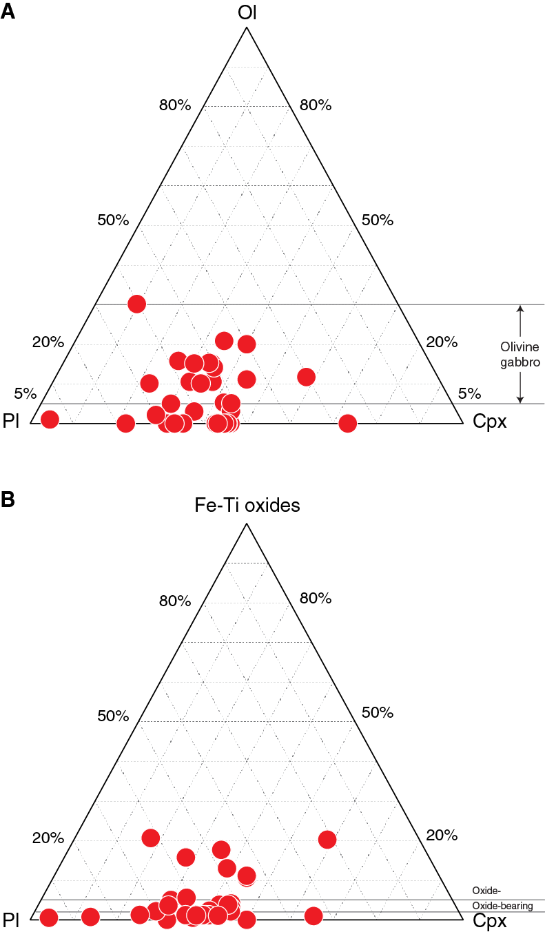
Figure F11. Olivine-plagioclase-clinopyroxene and oxide-plagioclase-clinopyroxene ternary diagrams, Hole 1105A.
Most of the thin sections examined are medium to coarse grained; two have mylonitic texture. We note that the deformed samples dominated by porphyroclastic or mylonitic textures at several places were not redescribed. Two thin sections have domains with different grain sizes (i.e., coarse-grained domain and fine-grained domain). Most of the medium-grained and some of the coarse-grained gabbros have granular textures in which subhedral to anhedral crystals form an interlocking matrix (Figure F12A–F12B). Most of the coarse-grained samples, however, have poikilitic to ophitic textures in which large, anhedral clinopyroxene crystals enclose or partly enclose euhedral to subhedral plagioclase crystals (Figure F12A) and subhedral to anhedral plagioclase crystals fill the space between the large oikocrysts. In a few samples, euhedral to subhedral olivine crystals are enclosed in subhedral to anhedral plagioclase (Figure F12B) and anhedral clinopyroxene oikocrysts. Rarely, plagioclase is enclosed in olivine (Figure F12C).
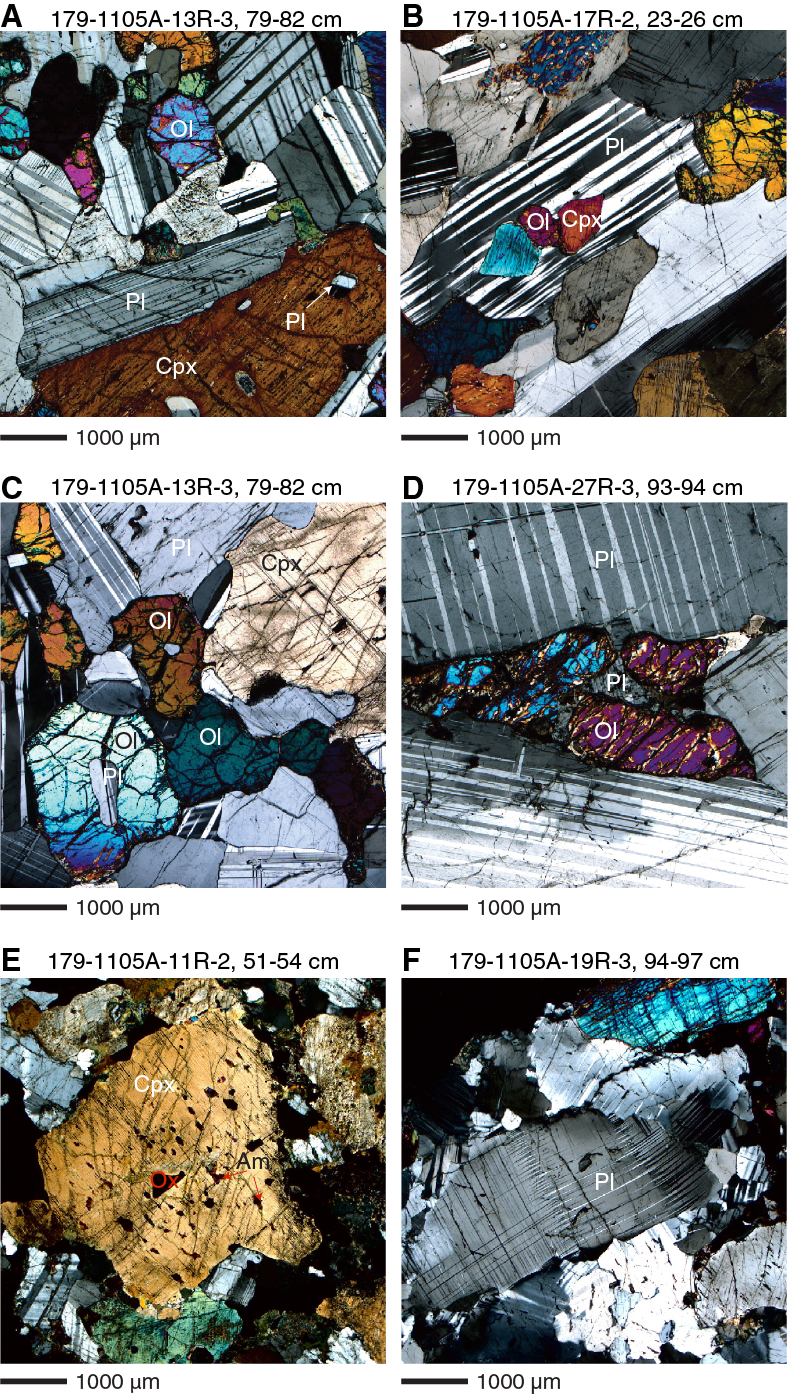
Figure F12. A. Olivine, plagioclase, and clinopyroxene. B. Clinopyroxene and olivine inclusions. C. Small equant plagioclase inclusions. D. Amoeboidal olivine. E. Blebs. F. Deformed plagioclase.
Undeformed plagioclase crystals vary from euhedral to anhedral. Elongate and subhedral crystals typically occur as laths with aspect ratios (length:width) of 3:1 to 5:1. Undeformed olivine occurs as rounded subhedral to anhedral crystals, anhedral amoeboidal crystals (Figure F12D), and anhedral ophitic to poikilitic oikocrysts. Subhedral olivine crystals are elongate parallel to extinction directions and typically have aspect ratios of 1:1.5 to 1:2. Clinopyroxene occurs as somewhat elongate crystals (aspect ratio = 1:2 to 1:3), anhedral crystals, and anhedral ophitic to poikilitic oikocrysts. Exsolution lamellae are well developed in clinopyroxene. Blebs of brown amphibole, opaque oxides, and sulfides are common in clinopyroxene (Figure F12E). Orthopyroxene is not abundant. Where found at all, it is often subequant. Brown amphibole is a widespread anhedral interstitial phase is commonly associated with opaque minerals; in some samples at least it appears to represent an original igneous phase. Green amphibole, in contrast, clearly derives from late-stage alteration of original clinopyroxene, olivine, or brown amphibole. Apatite and zircon occur as rare euhedral interstitial crystals or euhedral chadacrysts in opaque oxides and amphibole. Deformation and consequent development of undulose extinction in plagioclase makes the unambiguous recognition of compositional zoning difficult (Figure F12F). In some samples, however, multiple rectangular zones of changing extinction angle are present, and these roughly parallel the margins of the crystals. Weakly zoned clinopyroxene crystals are present in few samples.
Detailed observations and special features
Melt-crystal interactions and late-stage evolution
The textures of the intercumulus phases within olivine gabbro suggest that these rocks experienced melt-rock interaction processes likely related to a late-magmatic evolution. Olivine crystals are commonly surrounded by rims of orthopyroxene and brown amphibole, locally having irregular shapes and corroded grain boundaries (Figure F13A–F13B). Abundant brown amphibole also occurs as an interstitial phase between plagioclase and clinopyroxene (Figure F13C). In addition, clinopyroxene locally shows clear evidence for replacement by brown amphibole (Figure F13C–F13D).
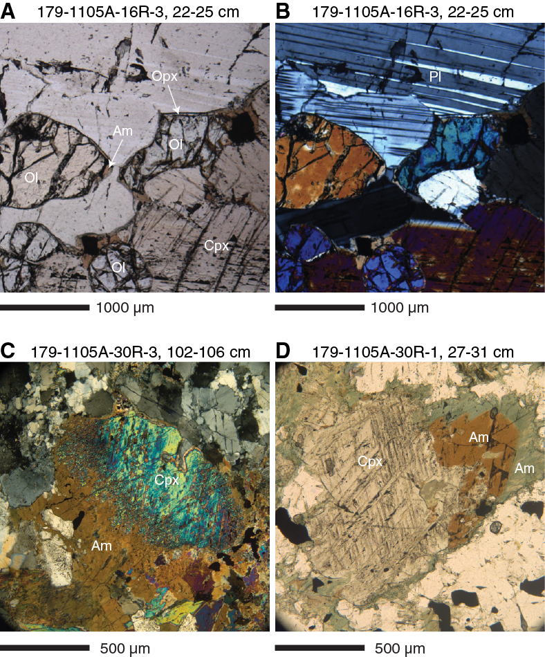
Figure F13. A, B. Olivine rimmed, Hole 1105A. C. Clinopyroxene overgrown. D. Clinopyroxene rimmed by intergrowth.
Brown amphibole rims/interstitial grains are commonly attributed to the crystallization of chemically evolved melts, produced either by extensive fractional crystallization (Meyer et al., 1989) or melt-crystal interaction processes (e.g., Coogan et al., 2001). Alternatively, the association of orthopyroxene and brown amphibole in rims around olivine can be related to hydrous partial melting of the gabbro triggered by the ingress of hydrothermal fluids in the still hot plutonic rocks (e.g., Koepke et al., 2005). The textural relationships between amphibole (Am) and clinopyroxene (Cpx) suggest that the first mineral formed through a reaction of the type
F Cpx + hydrous melt 1 = Am + melt 2.
This inference is consistent with the presence of a hydrous chemically evolved melt. The origin of this hydrous component can be either related to juvenile water concentrated after differentiation of a MORB-type melt or to a seawater-derived fluid added to the system either through assimilation of previously altered rocks or the ingress of hydrothermal fluids into the still hot plutonic rocks.
Oxide minerals and sulfides
Reflected light microscopy, not utilized during Leg 179, provides information on the mineralogy and paragenesis of oxide minerals and sulfides that occur in Hole 1105A cores. Their presence bears on the later development of one or more later liquid lines of descent, and the sequence of deformation and crystallization of the rocks. A general background and summary description for oxides and sulfides from Hole 735B is in Shipboard Scientific Party (1999b).
Briefly, Hole 1105A cores, like those of Hole 735B, contain the magmatic oxide minerals ilmenite and magnetite and the magmatic sulfide minerals pyrrhotite and chalcopyrite. Ilmenite is, formally, a solid solution (Ilss) between the end-members ilmenite and hematite, whereas magnetite is a solid solution (Mtss) between the end-members magnetite and ulvöspinel. In magmatic systems, the two oxide solid solutions are invariably intergrown, either because they coprecipitated from magma or they separated during subsolidus oxyexsolution:ulvöspinel from magnetite and hematite from ilmenite. Their basic distribution in the cores is either very little (but never none) in gabbro and olivine gabbro or a lot (1%–18% in the mode) in oxide-bearing and oxide gabbro. Zones of high and low oxide abundance alternate on the scale of a few to tens of centimeters throughout the cores. Coarse patches of magmatic oxides mainly occur in zones of high-temperature crystal-plastic deformation (porphyroclastic, gneissic, and mylonitic fabrics) or in former porosity structure in disrupted magmatic breccias. The oxides consistently conform to outlines of irregular and variably deformed silicate minerals, and fragments of the latter can be preserved throughout the oxide patches. Often the coarse patches of oxide grains outline a late-stage porosity structure, accessible to migrating late-stage magma, which was completely infilled by precipitating oxide minerals.
Even in rocks with very low proportions of opaque minerals, as observed using transmitted light, reflected light microscopy reveals that the traces occur as intergranular minerals together with brown amphibole. The traces consist of both magmatic oxides and sulfides or of magmatic sulfide only. Together, they comprise what might be termed an intergranular mineral association (Shipboard Scientific Party, 1999b). This intergranular association also occurs between silicate minerals in oxide gabbros carrying larger patches of intergrown ilmenite and magnetite, and it often occurs as small, elongate inclusions along cleavage surfaces in clinopyroxene in both oxide and olivine gabbros. In the intergranular association, and within inclusions, the tiny oxide minerals are irregular in shape, and the sulfides are either rounded or conform to the outlines of confining crystals. Idiomorphic relationships are that the brown amphibole crystallized after the sulfides segregated as immiscible droplets and were captured within the tiny spaces either together with, or somewhat after, the intergranular oxides. The intergranular association then is present at least as traces in all thin sections from Hole 1105A. Petrogenetically, in ideally pure olivine gabbro adcumulates, from which almost all interstitial silicate liquid was removed by compaction or more intense deformation, these tiny dregs are all that is left as crystalline products of those liquids.
Finely crystalline secondary magnetite also occurs, usually in fractures or altered regions of olivine. Secondary sulfides, chiefly pyrite, occur in fractures crossing all previously formed minerals and can completely replace primary magmatic sulfides. The key to distinguishing magmatic from secondary magnetite is the presence of ilmenite in complex intergrowths with magnetite, which texture is never secondary. Crystals of secondary magnetite are also tiny, faceted, and in many instances linked in chains (Figure F14A). They may also be associated with green amphibole or clays, produced under intermediate-grade greenschist facies hydrothermal conditions or at low temperature, respectively. In some rocks, green amphibole has completely replaced brown amphibole, and in others brown amphibole only survives within the cleavage inclusions in clinopyroxene.
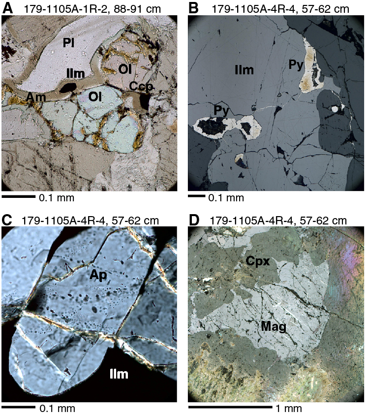
Figure F14. Magmatic oxides and related minerals in thin section, Hole 1105A.
Magmatic oxide minerals and sulfides are intimately associated, the sulfides often appearing with rounded outlines in more massive aggregates of ilmenite and magnetite (Figure F14B). The rounded outlines indicate that the sulfides are relics of immiscible segregation at magmatic temperatures (>700°C; Czamanske and Moore, 1977) within the highly differentiated and iron titanium–rich liquids that were also crystallizing the oxide minerals. Onset of liquidus crystallization of magnetite in MORB results in rapidly diminishing FeO contents in differentiated MORB glasses. The solubility of S in basaltic melts being strongly correlated to the iron contents, a strong S decrease is associated with magnetite crystallization (Perfit and Fornari, 1983; Natland et al., 1991). This in turn accelerates sulfide segregation. The sulfide globules at this stage of differentiation crystallize upon further cooling to pyrrhotite and chalcopyrite, which are what is seen in the rocks of Hole 1105A. The chalcopyrite often occurs as flamelike intergrowths in pyrrhotite, but the external rounded form of the overall sulfide aggregate remains. The compound oxide sulfide aggregates often have rims of brown amphibole, which proves to be largely titanian pargasite when investigated by electron probe microanalysis (e.g., Ozawa et al., 1991; Maeda et al., 2002). This is present even as trace interstitial amounts in olivine gabbros and gabbros, where it forms rims around the small irregularly shaped magmatic oxides and globular sulfides.
In several oxide gabbros from Hole 1105A, magmatic apatite also occurs within or in clumps adjacent to the larger patches of magmatic oxides. The apatite crystals are equant and subrounded but in any case are neither recrystallized nor disrupted by crystal-plastic deformation (Figure F14C). Taken together, the apatite crystals, rounded sulfides within patches of intergrown ilmenite and magnetite, the coarse grain size of intergrown ilmenite and magnetite, and the presence of coarse exsolution lamellae in both ilmenite and magnetite in larger patches of the oxide minerals (Figure F14D) attest to lack of crystal-plastic deformation of the oxides, despite extensive deformation of silicate minerals in the same thin sections. That is, there is no sign of such deformation in most of the coarse oxide patches, even though silicate mineral grains, chip, and aggregates within them are deformed in like manner to surrounding rock. A few rocks show late mylonitic or cataclastic disruption of the edges of oxide sulfide patches where they are fragmented and redistributed along narrow very fine grained seams. The idiomorphic relations are that (1) segregation of globular sulfides occurred continuously from earlier stages of basaltic differentiation but the blebs remained molten through subsequent magmatic cooling; (2) the silicate crystal framework was variably deformed; (3) crystallization of oxide minerals and, shortly afterward, apatite took place; (4) the early formed oxides, segregated sulfide globules, and apatite became encased in coarse ilmenite–magnetite intergrowths; and (5) in some cases, oxyexsolution of ilmenite and magnetite followed.
In thin section, no apparent relationship between oxide gabbros and either felsic veins or smaller segregations occurs, although this was a consistent (but not universal) pattern in Hole 735B, and might be expected as a result of continuing extended differentiation (Natland et al., 1991; Shipboard Scientific Party, 1999b; Natland, 2002).
An important remaining question is whether coarse oxide patches, which are so intimately associated with zones of intense deformation, themselves experience extensive deformation or dissolution–recrystallization, and then later were annealed to their current coarse-grained fabric. If that happened, then it did so without disrupting the apatite and sulfide globules within them, not to mention the coarse oxide minerals, and all textural evidence that can be seen with a microscope for such prior deformation of the oxide minerals has disappeared. To what extent did deformation occur both above and below the oxide solidus?
Rock types and geochemistry
As no working halves of the Hole 1105A cores were on board, no new geochemical measurements were performed during Expedition 360 on Hole 1105A rocks. Please refer to the Leg 179 Initial Reports volume for whole-rock geochemistry (Pettigrew, Casey, Miller, et al., 1999).
Metamorphic petrology
Hole 1105A rocks record the superposition of minerals of different paragenesis that have overprinted the magmatic igneous assemblages in response to fluid interaction under progressively decreasing temperature conditions. Four types of alteration are apparent throughout the cores: (i) static background alteration without direct relations to veining and deformation, (ii) vein-related alteration, (iii) recrystallization associated with crystal-plastic deformation, and (iv) alteration related to cataclasis.
Static background alteration
Downhole distribution
Variations in static background alteration intensity and mineralogy down Hole 1105A are reported in Figure F15. Most gabbros (83% of the total) show <30 vol% of secondary minerals related to static alteration, whereas extensive static alteration (≥60 vol%) is rare (<3% of the total). Static alteration intensity shows no trend with stratigraphic depth. Olivine and plagioclase, respectively, are generally the most and the least altered phases. Olivine alteration is highly variable and no clear pattern in the distribution throughout Hole 1105A is evident. Total alteration of olivine is common at 35–68, 100–102, 117–119, and 145–153 m CCSF. Plagioclase is substantially altered only when the host rock displays intense veining or cataclasis. Conversely, away from veining and cataclasis intervals (86–96, 128–134, and 141–146 m CCSF), plagioclase alteration is negligible.
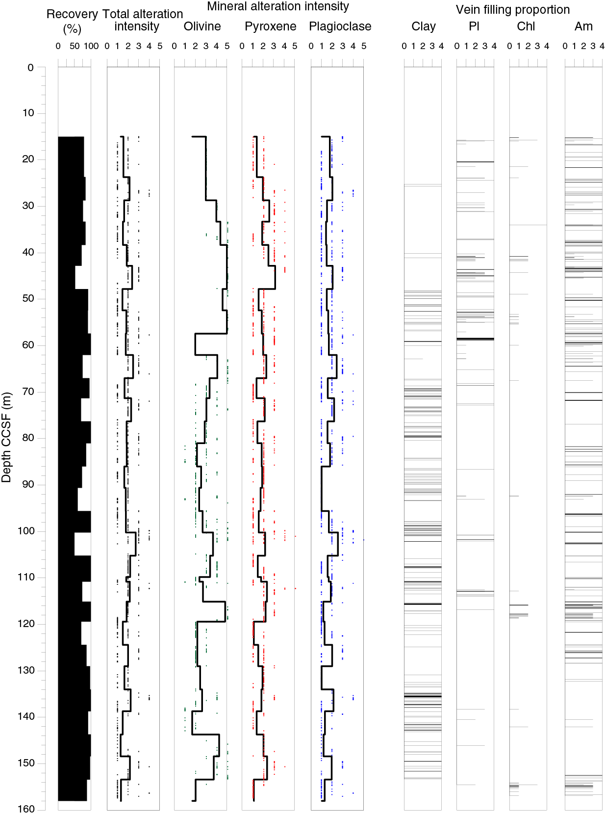
Figure F15. Downhole alteration intensity of primary igneous phases and occurrence of vein filling minerals, Hole 1105A.
Like plagioclase, oxide minerals in the gabbroic rocks do not typically show significant replacement by secondary minerals in hand sample. Oxide gabbro intervals are not more intensely altered than adjacent oxide-poor gabbroic rocks, a single exception being the oxide gabbro at 100–102 m CCSF, which is characterized by a high degree of alteration. Felsic veins, in marked contrast, tend to be substantially more altered than their host gabbros (see below). The extensive alteration of plagioclase in felsic veins is shown, for example, at 27–28 m CCSF (Figure F15). A relatively high alteration intensity in gabbros is often observed near contacts with felsic veins. Static alteration is also extensive where cataclasites and carbonate veins are present (e.g., at 130–132 m CCSF).
High-temperature alteration
In thin section, clinopyroxene is locally partly altered to secondary clinopyroxene and/or brown hornblende (Figure F16). Secondary clinopyroxene occurs at the rims of primary clinopyroxene and contains blebs of brown hornblende locally associated with opaque minerals. Brown hornblende also replaces primary magmatic clinopyroxene as thin discontinuous rims or films along cleavage surfaces and, less frequently, as micro veins within it. The alteration of magmatic clinopyroxene into secondary clinopyroxene and/or brown hornblende is not associated with any apparent alteration of olivine and plagioclase. This alteration may be attributed either to reaction of clinopyroxene with a late-stage deuteric melt or fluid exsolved from melt under near-solidus conditions or to a seawater-derived fluid under granulite–upper amphibolite facies conditions.
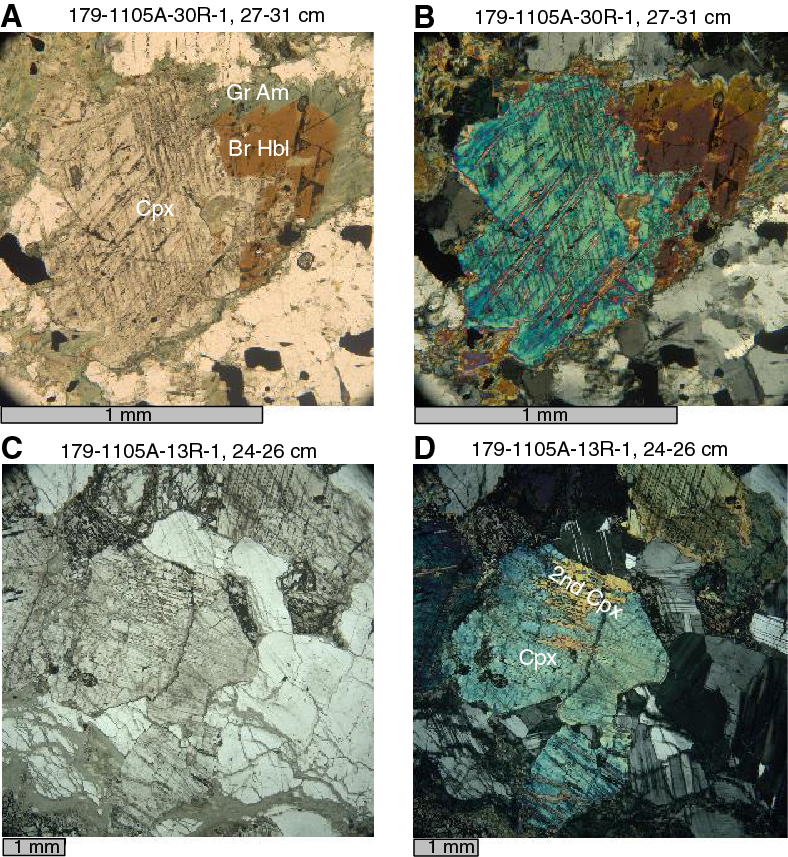
Figure F16. Clinopyroxene alteration, Hole 1105A.
Moderate-temperature alteration
The background static alteration minerals vary in conjunction with the nature of the primary mineral. In particular, variable replacement modes were observed for olivine. Olivine is commonly altered to talc and minor oxide aggregates, frequently with an outer rim of chlorite where it is in contact with plagioclase (Figure F17A–F17B). A less frequent mode of olivine alteration is represented by local aggregates of chlorite and pale green amphibole in coronas along plagioclase contacts. Olivine is also locally replaced by mesh-textured serpentine and minor oxides. Clinopyroxene is altered along rims, cleavage surfaces, and micro veins to green amphibole (Figure F16), which is locally associated with a pale green amphibole (most likely actinolite) and oxides. In addition, if brown hornblende associated with clinopyroxene is present, it is commonly rimmed by green to pale green amphibole. Plagioclase hydrothermal alteration is mostly confined to development of chlorite along the contacts with primary mafic minerals and within micro veins, frequently in association with minor secondary plagioclase. Primary oxides locally show titanite coronas. As a whole, the static alteration mineral assemblages are consistent with those described by the Leg 179 shipboard scientists (Pettigrew, Casey, Miller, et al., 1999; see also Casey et al., 2007) as “pervasive alteration or dominant metamorphism,” which were attributed to greenschist facies metamorphic conditions.
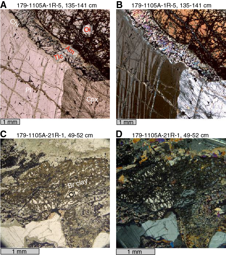
Figure F17. Olivine and plagioclase alteration, Hole 1105A.
Low-temperature alteration
Late-stage hydrothermal alteration implying oxidative conditions is represented by crystallization of orange-brown clay throughout Hole 1105A, mostly at the expense of olivine (Figure F17C–F17D). In places, the orange-brown clay entirely replaces olivine. This is particularly common at the top of Hole 1105A (15–36 m CCSF). At greater depths, olivine replacement by orange-brown clay corresponds to intervals characterized by a high intensity of veins filled with orange-brown clay. In plagioclase and clinopyroxene, the formation of orange-brown clay is commonly restricted to micro veins.
Veins
Metamorphic veins
Together with the structural geology team, we recorded 737 discrete veins or networks of veins. Of these veins, 82% correspond to metamorphic veins and 18% to magmatic veins, the latter being exclusively of felsic composition. Among the metamorphic veins, 42% consist of a very soft material (mostly whitish but sometimes also brownish) that was classified as “clay.” Shipboard identification by X-ray diffraction was not possible, as only archive halves were available on the R/V JOIDES Resolution during Expedition 360. This whitish/brownish material was not seen in thin section and was most likely lost during sample preparation. Veins of this type are also associated with zones of strong cataclastic deformation (see Alteration related to cataclasis and Structural geology). Their distribution with depth correlates with intervals where the total static alteration intensity is high, including those where the amount of brown clay replacing olivine was the highest (see above). Low-temperature carbonate veins are also present toward the bottom of Hole 1105A and constitute 1% of the metamorphic veins. In some intervals, carbonate also fills open fractures, sometimes with a marked zonal structure along veins, implying multiple phases of precipitation from hydrothermal fluids (see Figure F38). A total of 40% of the metamorphic veins are characterized by dark green to blackish color largely (and sometimes totally) consisting of amphibole (abundance classes >90% and 60%–90%; see also Structural geology). The remainder of the metamorphic veins (17%) are whitish to greenish and are mainly composed of secondary plagioclase, chlorite, and amphibole (with amphibole < 60 vol%).
Our results for Hole 1105A vein fillings are similar to those of the Leg 179 shipboard scientists (Pettigrew, Casey, Miller, et al., 1999; see also Casey et al., 2007), although they did not present quantitative estimates on the amount. They divided the veins into three classes: (i) actinolite and/or chlorite vein fill mineral assemblages, (ii) higher-temperature brown amphibole veins, and (iii) lower-temperature veins filled with altered calcite-silicate, carbonate, and smectite-zeolite.
Under the microscope, veins indicating formation at different temperature regimes were detected. The most common vein-forming mineral in the dark green to blackish veins is amphibole, often in association with chlorite and secondary plagioclase. Veins filled with brownish green hornblende forming larger, up to 1 mm long crystals, sometimes in direct contact with millimeter-sized clusters of brown-green hornblende, are presumed to have formed under amphibolite facies conditions (Figure F18A–F18B). Other veins, namely those formed in a brittle regime, are characterized by aggregates of tiny pale green actinolitic amphibole needles associated with chlorite (Figure F18C–F18D). These veins likely developed under greenschist facies conditions.
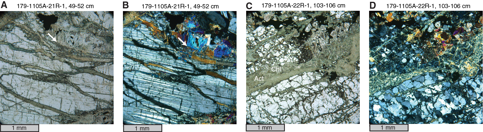
Figure F18. Types of amphibole veins in gabbros, Hole 1105A.
Alteration of felsic veins
In contrast to host gabbros, which show variable low to moderate degrees of alteration, all the felsic veins are extensively altered, with background alteration intensities ranging from 60% to 100% and averaging ~90%. The most common alteration mineral is secondary plagioclase, often in association with amphibole and sometimes with chlorite. Quartz, if present, has orange staining, probably produced by tiny inclusions of iron oxides or hydroxides. In places, secondary oxide, sulfide, and whitish to greenish clay minerals were observed. The marked contrast in alteration intensity between the felsic veins and host gabbros implies that these veins were also pathways for significant late-stage hydrothermal fluid flux. The emplacement of the felsic material may have followed tectonically induced zones of weakness that later became pathways for hydrothermal circulation. Alternatively, the substantial hydrothermal alteration in these zones is related to the permeability contrast between the felsic and the gabbroic rocks.
Recrystallization associated with crystal-plastic deformation
The high-temperature alteration is largely associated with crystal-plastic deformation. Mylonitic rocks occur sporadically throughout the cores and are characterized by recrystallization of clinopyroxene and plagioclase with or without olivine and oxides. Neoblastic plagioclase and olivine form monomineralic, nearly polygonal aggregates, and neoblastic clinopyroxene is locally associated with minor brown hornblende (Figure F19). Relatively large quantities of brown hornblende are present in ultramylonitic bands in association with neoblastic clinopyroxene and/or plagioclase (Figure F20), thereby suggesting that the crystal-plastic deformation event was at least locally assisted by H2O-rich agents. Taken as a whole, the neoblastic minerals document crystal-plastic deformation under granulite–upper amphibolite facies conditions for the event.

Figure F19. A, B. Whole thin section images of mylonitic olivine gabbro.
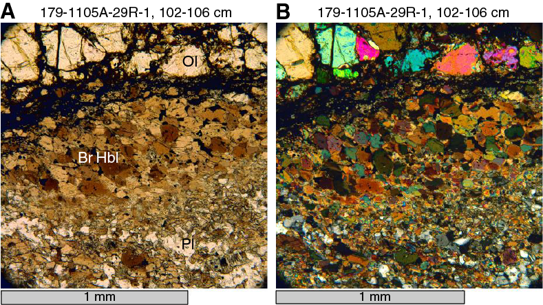
Figure F20. Aggregates dominated by brown hornblende.
Alteration related to cataclasis
Brownish/whitish veins, which probably consist of clay mineral(s) and carbonate(s), are conspicuous in a few intervals with significant cataclastic deformation. In these intervals, fragmented crystals and gabbro clasts are highly altered. Olivine and pyroxene are mainly replaced by reddish brown clay or by mixtures of clay and iron oxyhydroxides (Figure F21). Similar clay and carbonate veins and brownish clay pseudomorphs after olivine and pyroxene, though less abundant, also occur in host gabbros near the cataclastic zones. These observations suggest a close relationship between cataclastic deformation and sub-greenschist facies conditions.
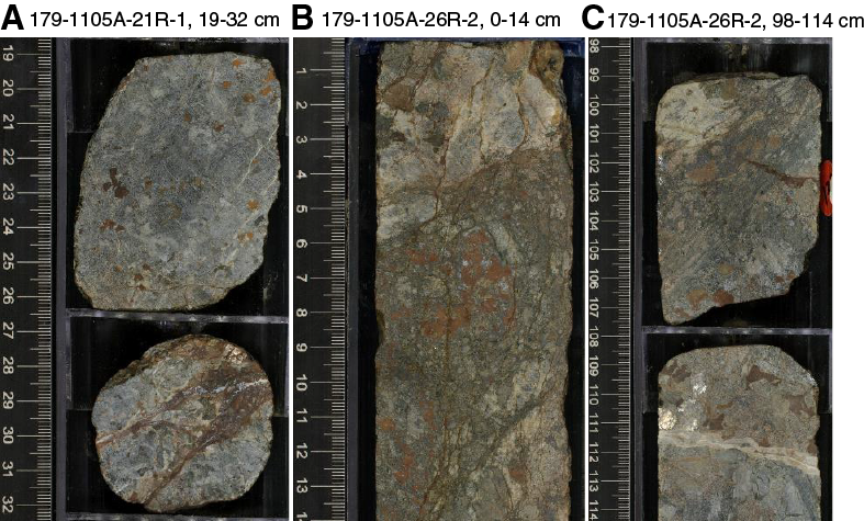
Figure F21. Cataclastic intervals with brownish/whitish veins and brown clay pseudomorphs, Hole 1105A.
Structural geology
Cores from Hole 1105A were logged and analyzed by the structural geology team at the start of Expedition 360 during the transit to Atlantis Bank. This was done with the dual objectives of familiarizing Expedition 360 scientists with the types of lithologies and structures to expect for the remainder of the expedition and documenting Hole 1105A structures using the exact same scheme employed for Holes 735B and U1473A (see Structural geology in the Expedition 360 methods chapter [MacLeod et al., 2017]).
Five broad structural features were measured and described: magmatic contacts and veins, magmatic fabrics and layering, CPFs, alteration veins, and brittle deformation. Observations are presented in order of decreasing temperature, starting with igneous contacts and proceeding to brittle deformation. The details of how each item was logged and described, including microstructures, are provided in Structural geology in the Expedition 360 methods chapter (MacLeod et al., 2017). Cores from Hole 1105A had already been described and the results presented in detail in the Leg 179 Initial Reports (Pettigrew, Casey, Miller, et al., 1999). All Leg 179 shipboard thin sections had also been described previously, so the descriptions presented here were made on a subset of the thin sections selected to represent the macroscopic structures observed.
The distribution and intensity of structures observed and measured in Hole 1105A cores are broadly in agreement with the results of Pettigrew, Casey, Miller, et al. (1999). The most important conclusion from both studies is that crystal-plastic deformation is limited in the upper hole compared to the sections of Holes 735B and U1473A. The proportion of cores with magmatic fabrics, the degree of alteration, and the extent of fracturing and faulting is comparable with that observed in Hole 735B.
Magmatic veins
A total of 122 veins of magmatic or probable magmatic origin were recorded in Hole 1105A cores. The veins are felsic and although moderately to heavily altered, reflect original compositions that range from leucogabbro through trondhjemite to quartz diorite. They contain assemblages of plagioclase + clinopyroxene ± brown hornblende ± amphibole ± biotite ± alkali feldspar ± quartz ± titanite ± apatite ± zircon. Veins occur as planar features with widths ranging from 1 mm to 5 cm, as irregular patches a few centimeters in diameter, and sometimes as vein networks (Figure F22). The veins make up ~1.1% ± 0.2% of the recovered core volume and are concentrated shallower than 65 m CCSF and deeper than 138 m CCSF in the hole (Figure F23). Very few veins were identified between 75 and 135 m CCSF.
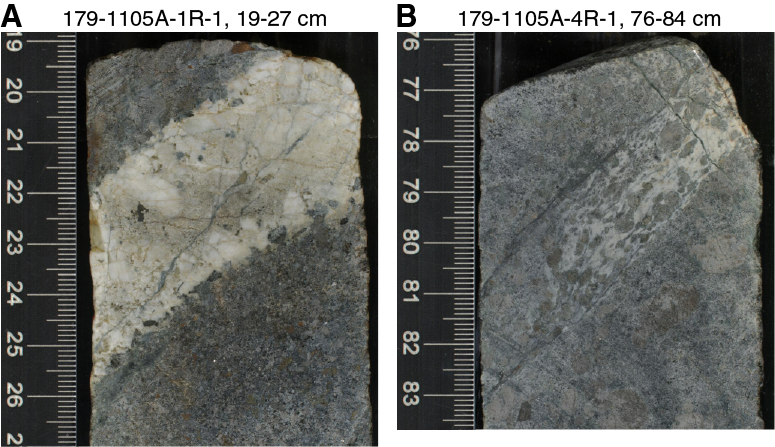
Figure F22. Magmatic veins, Hole 1105A.

Figure F23. A. Frequency dip distribution of magmatic veins, Hole 1105A. B. Depth dip distribution of magmatic veins.
Most of the magmatic veins have not suffered crystal-plastic deformation; however, some rare leucocratic gabbro veins show mylonite-grade deformation. In the latter case, strain is localized within these veins and not in the host rock, as demonstrated by sharp boundaries with the relatively undeformed surrounding gabbro. This is best shown by interval 179-1105A-4R-1, 76–84 cm (Figure F22B), in which the plagioclase has completely recrystallized and the pyroxenes form porphyroclasts with tails of neoblasts. The CPFs are oriented such that the foliation plane is parallel to the margins of the vein. However, most other veins are undeformed and crosscut any CPFs present in the host gabbros. The two contact relationships between veins and host rocks indicate that at least two generations of felsic veins are present: one population intruding before or during the period of crystal-plastic deformation and one population largely intruding after the deformation had ceased.
Magmatic veins have a range of orientations from vertical to horizontal and a mean dip of 41° (standard deviation = 24°). Figure F23 illustrates that the range of measured dips departs from that expected for a random distribution (see Structural geology in the Expedition 360 methods chapter [MacLeod et al., 2017]), with a slight excess of dips of 10°–20° and 40°–50° together with a deficiency of dips between 60° and 80°. This dip distribution is very similar to that for Hole 735B (Dick, Natland, Miller, et al., 1999), which shows two peaks for 20°–30° and 50°–60°.
Magmatic contacts and crosscutting relationships
A total of 67 magmatic contacts were directly observed in the core in coordination with the igneous petrology team. These correspond to boundaries between lithologic intervals that are interpreted as either intrusive (23% of all contacts), gradational as defined by grain size or modal variation (65%), or sheared/structural (12%). Structural contacts are defined by crystal-plastic shear zones that separate different igneous intervals (Figure F24). Excluding sheared or structural contacts, dips range from 0° to 90°, have a distribution that peaked at 30°–60°, and a mean dip of 43° (standard deviation = 24°) (Figure F25A). Magmatic contacts display no systematic downhole trend other than being sparse in the upper 20 m of Hole 1105A (Figure F25B).

Figure F24. Sharp structural contact between a largely undeformed olivine gabbro and a crystal-plastically deformed olivine-bearing oxide gabbro.
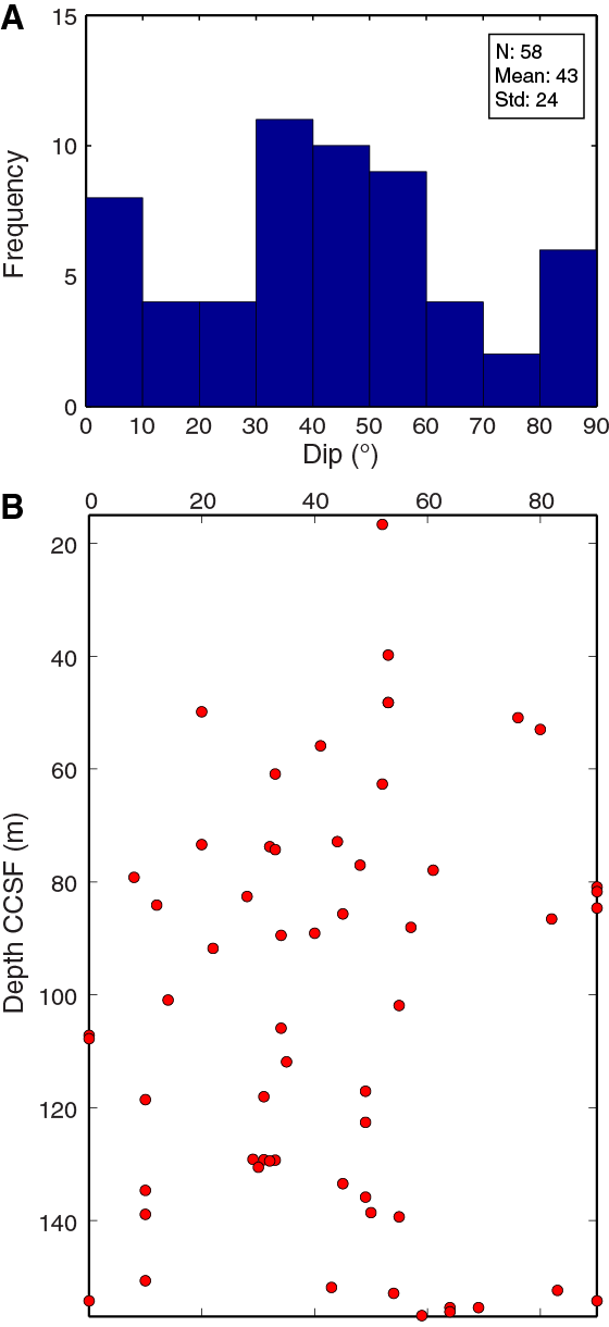
Figure F25. A. Frequency dip distribution of magmatic contacts, Hole 1105A. B. Depth dip distribution of magmatic contacts.
Thin (up to 20 cm wide) and sometimes irregular (fine-grained) bodies of microgabbro were found within the coarse- and medium-grained olivine gabbro throughout most of the core. These microgabbro bodies exhibit several different types of contacts with their host gabbro, ranging from sharp and planar to diffuse and irregular (Figures F26, F27). The microgabbros are sometimes clearly intrusive (Figure F27A), but in other cases, the nature of their contacts is more ambiguous and may represent original magmatic layering that has been modified by deformation. Often the microgabbro bodies exhibit a weak magmatic foliation parallel to the contacts with the undeformed coarse-grained host rock. Sometimes the microgabbro is clearly recrystallized and exhibits equilibrated plagioclase textures, but even in these cases samples often preserve an original magmatic foliation. No example of fine-grained microgabbro crosscutting the crystal-plastic foliation was observed, indicating that the microgabbro bodies must have intruded prior to crystal-plastic deformation. Crystal-plastic foliations often overprint both the fine-grained microgabbro and the coarse-grained gabbro (Figure F27C). Further, the complicated and irregular geometry of some of the contacts and the recrystallized textures of the microgabbro bodies indicate that intrusion may have occurred into hot, sometimes partially molten host rock. Rarely, a foliated microgabbro body shows evidence of being cut by a late, narrow, high-temperature shear zone (Figure F28), reflecting the protracted history of intrusion and deformation recorded in the cores.
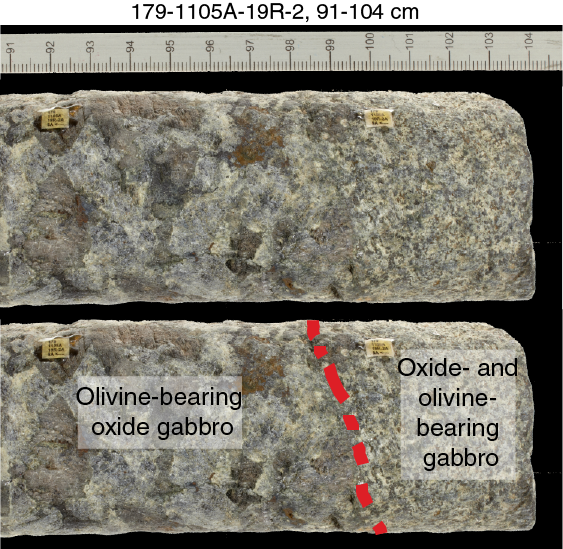
Figure F26. Relatively gradational contact between mostly undeformed fine-grained intrusive olivine- and oxide-bearing gabbro and slightly crystal-plastically deformed olivine-bearing oxide gabbro.
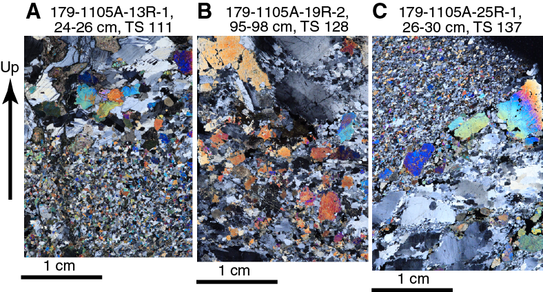
Figure F27. Different contact styles between intruding microgabbros and their coarser-grained gabbro hosts.
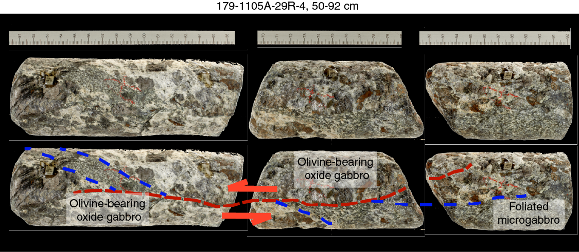
Figure F28. High-temperature deformation crosscutting relationships, Hole 1105A.
Magmatic fabrics
Gabbroic rocks from Hole 1105A have medium- to coarse-grained granular and subophitic textures with poikilitic pyroxene crystals. Magmatic textures (i.e., isotropic or showing crystal shape-preferred orientations [SPOs]) are well preserved in ~80% of the observed intervals with variably developed magmatic fabrics (Figure F29). The other 20% of the cored interval is characterized by crystal-plastic deformation that partially or potentially completely obscures the previous magmatic texture. The original magmatic fabric may be preserved in intervals where crystal-plastic deformation intensity is lower than Rank 2 (see Structural geology in the Expedition 360 methods chapter [MacLeod et al., 2017]). For example, the interval 50–55 m CCSF is weakly crystal-plastically deformed and is characterized by preserved igneous minerals weakly oriented. In general, magmatic fabrics are weakly developed and overall defined in hand sample by aligned laths of pyroxene. Thin section observations (see Microstructures) were used to confirm the presence and intensity of magmatic fabrics, when possible. Contacts or gradients between different fabric intensities (i.e., from intensity Rank 1 to 2) were not evident. When contacts or gradients are observed, the boundaries between weak and moderate magmatic fabrics are related to variations in grain size from coarse-grained isotropic gabbros to medium- and fine-grained foliated material, because the foliation is better developed/observed in finer grain sizes. Magmatic lineations were not observed.
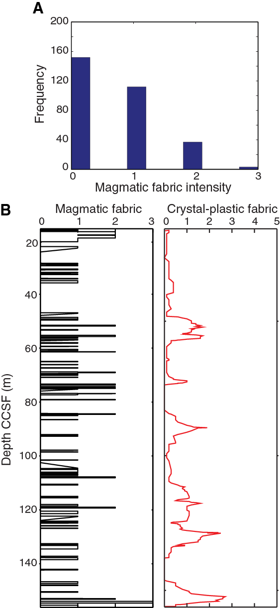
Figure F29. A. Histogram of magmatic fabric intensity, Hole 1105A. B. Variation of magmatic fabric intensity with depth.
Magmatic fabric dips are randomly distributed, ranging between 20° and 55° (Figure F30). Discrete intervals of locally shallower and steeper dip angles were also measured. Subvertical intervals with dips of 66° and 70° were described at 84 m CCSF and within the interval 148–156 m CCSF. However, no systematic variation in dip is observed with depth.
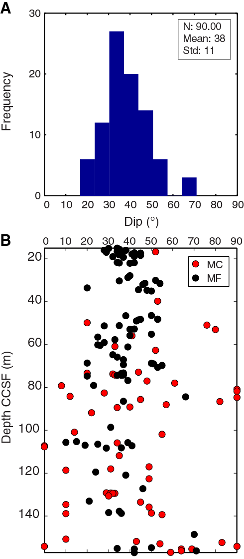
Figure F30. A. Frequency distribution of magmatic fabric dips, Hole 1105A. B. Depth distribution of magmatic fabric and magmatic contact dips.
The relationship between magmatic fabrics (occurrence, intensity, and orientation) and magmatic contacts varies. Throughout the interval 15–80 m CCSF in Hole 1105A, we observed some cases where weakly developed magmatic fabrics occur adjacent to magmatic contacts. In these cases, the magmatic fabric and magmatic contact are subparallel (Figure F30). For example, at ~56 m CCSF the dip of the magmatic fabric is 37° and the igneous contact has a dip of 40°. Magmatic contact dips are more variable deeper than 80 m CCSF, making it difficult to assess the relationship between magmatic fabric formation and orientation near magmatic contacts. However, microgabbro intervals that crosscut gabbro often have a magmatic fabric subparallel to the contact (see Magmatic contacts and crosscutting relationships above).
Crystal-plastic fabrics
Crystal-plastic fabric downhole distribution
Cores logged from Hole 1105A show a heterogeneous distribution of CPFs with depth (Figure F31). Overall, the thickness of crystal-plastic deformation zones increases slightly downhole, with the most deformed zones located deeper than 80 m CCSF. The upper 50 m of the hole is relatively undeformed, especially compared to the top of Hole 735B. The interval 40–150 m CCSF is marked by alternation of the CPF intensity, going from progressively weakly foliated (Rank 1) to porphyroclastic/mylonitic (Rank 3/4). The coarse-grained porphyroclastic foliation (Rank 3) progressively grades to meter-thick shear zones composed of plagioclase-rich bands.

Figure F31. CPF intensity with depth, Hole 1105A.
Shear zones are overall gently to moderately dipping with a predominance of intermediate dips (Figure F32). The dip frequency distribution reveals a mean dip value of 35° for the shear zones in Hole 1105A. There are intervals where the dip is shallower (e.g., 50–60, 80–90, and 120–140 m CCSF). Deeper than ~100 m CCSF where there are more CPFs present compared to the upper part of the hole, the dip is more variable.
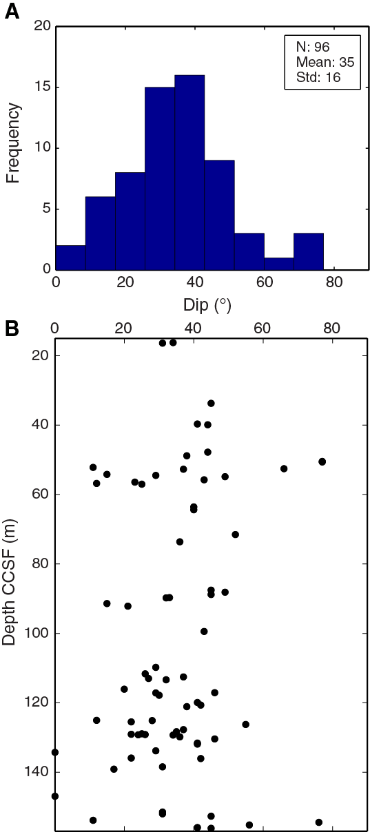
Figure F32. A. Frequency distribution of CPF dips, Hole 1105A. B. Depth distribution of CPF dips.
Solid-state recrystallization and mylonite development
Deformation is typically partitioned between the phases present, with plagioclase being the most common phase to deform plastically, whereas olivine shows moderate recrystallization and clinopyroxene is generally fractured, an observation also made in Hole 735B (Dick, Natland, Miller, et al., 1999).
A change in deformation style can be observed from top to bottom; the top 15–40 m CCSF interval is characterized by weakly to moderately foliated zones that are crosscut by sharp centimeter-thick mylonite zones. The boundaries of the mylonitic shear zones are sharp (Figure F33). Deeper than 100 m CCSF, thicker shear zones dominate. Plagioclase and clinopyroxene are completely recrystallized into medium- to coarse-grained asymmetrical monomineralic layers and porphyroclasts, respectively, and several oxide-rich zones are observed parallel to the foliation forming a gneissic texture (Figure F34). In contrast with the top of the hole, the boundaries of these shear zones are mostly gradational with the undeformed rock.
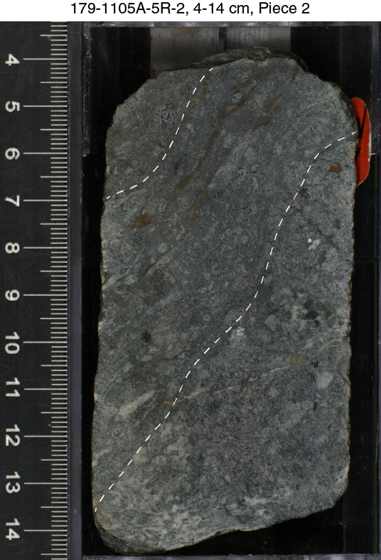
Figure F33. Typical aspect of ductile shear zones with sharp boundaries, Hole 1105A.
Figure F34. High-temperature solid-state foliation, Hole 1105A.
Alteration veins
Vein distribution
Alteration veins observed in Hole 1105A largely fill preexisting cracks and fracture networks and are variably distributed downhole. The alteration vein density in Hole 1105A is generally low, with an average vein density of ~1 vein per 10 cm (Figure F35A). Several areas of high vein density deeper than 100 m CCSF correlate with fracture and fault zones (Figure F35; see Brittle deformation below).
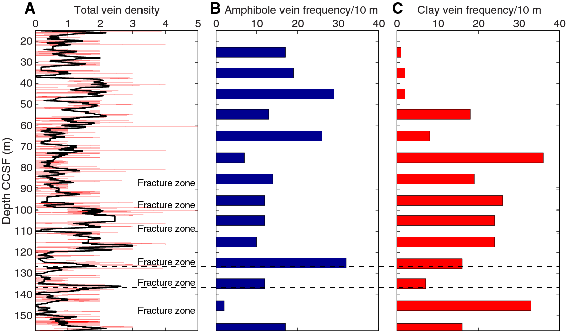
Figure F35. Metamorphic vein density and vein fill proportion with depth, Hole 1105A.
In general, two types of veins can be identified: (1) higher-temperature amphibole veins that are either steeply (>70°) or moderately (20°–70°) dipping and (2) late-stage clay and carbonate veins that have orientations ranging from steeply dipping to subhorizontal. The distribution of amphibole veins varies greatly throughout the hole with two local maxima, characterized by more than 20 amphibole veins per 10 m, at 40–50 and 60–70 and at 120–130 m CCSF, but are concentrated in the upper 70 m CCSF and absent deeper (Figure F35B). In contrast, clay veins are rare throughout the uppermost 50 m CCSF and increase substantially at ~70–80 m CCSF (Figure F35C). Clay vein frequency correlates inversely with amphibole vein frequency, as exemplified in Figure F35 by intervals 70–80 and 140–150 m CCSF. For a detailed investigation of the vein fill mineralogy see Metamorphic petrology.
Vein dip
Vein orientations were measured throughout Hole 1105A except for discontinuous and small veins between 80 and 110 m CCSF (Figure F36). Veins in this interval are infrequent and isolated (i.e., their length is contained within a core piece) with lengths of 1–3 cm. Amphibole veins have an average dip of 55° with a standard deviation of 16°. Steeply dipping isolated amphibole veins are common, along with the other types of veins. However, their isolated nature does not allow for the orientation to be confidently measured; therefore, these veins are not represented in Figure F36. Comparison of the vein orientation with a theoretical distribution of a random set of planes in a vertical borehole indicates that the overall amphibole vein dip distribution in Hole 1105A is not random with fewer shallow dips and predominance of intermediate to steep dips (see Structural geology in the Expedition 360 methods chapter [MacLeod et al., 2017]).
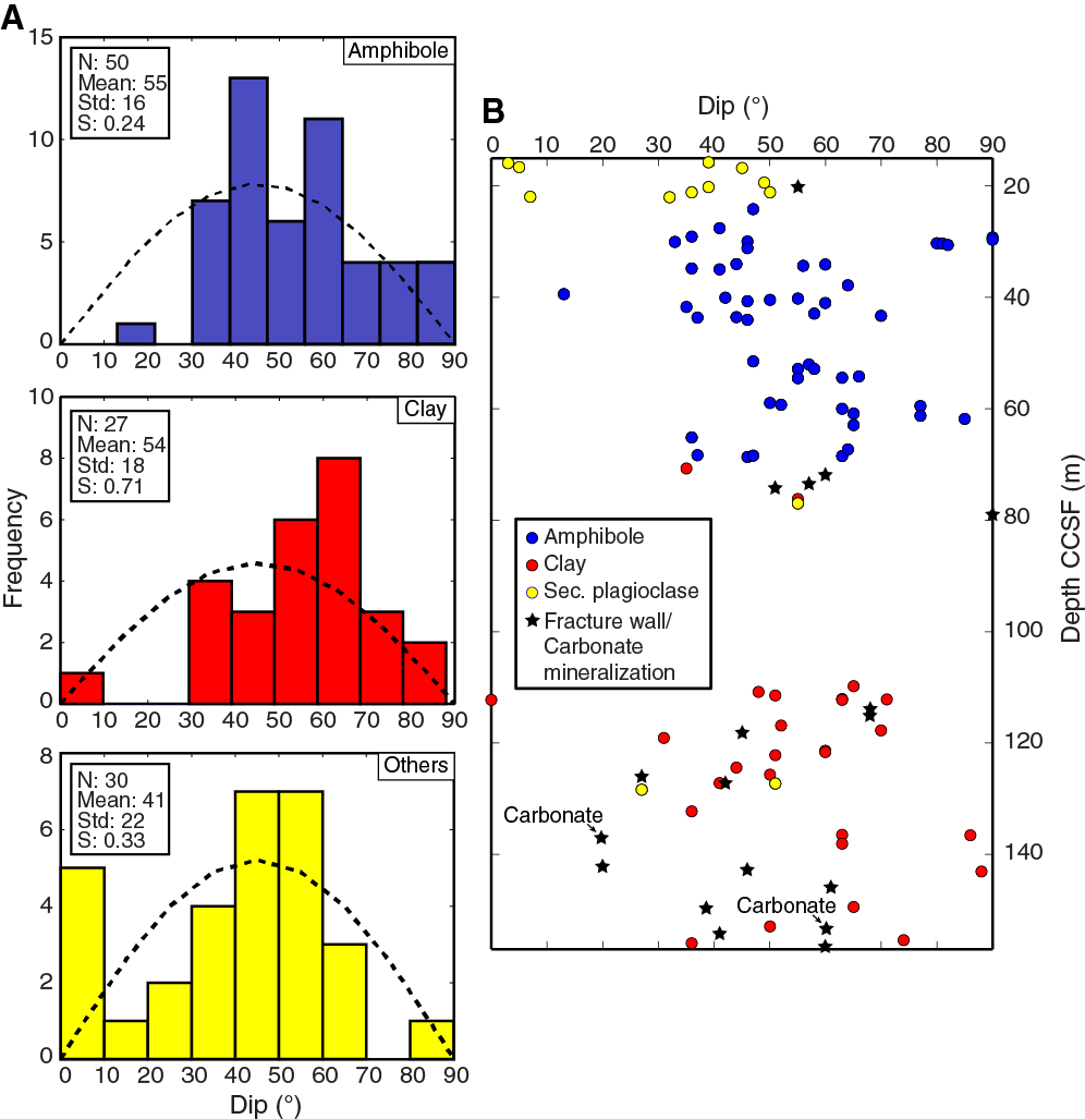
Figure F36. Dip of amphibole, clay, and other veins, Hole 1105A.
Clay veins are typically isolated with an average thickness of 0.5 mm. Single veins extending through the core piece (greater than ~5 cm) are represented in Figure F36 and have a dip of 54° with a standard deviation of 18°. Comparison to a theoretical random distribution of veins indicates that the clay vein dip distribution is not random with few shallow dips present. Other veins, encompassing secondary plagioclase veins and fractures partly filled with carbonate, have an average dip of 41° with a standard deviation of 22° and display a nonrandom distribution (Figure F36A), in this case with a significant number of subhorizontal veins.
Vein shape and structure of vein-filling material
Metamorphic vein morphologies observed in Hole 1105A can be divided into three categories: (1) irregular (54%), (2) planar (35%), and (3) curved (10%), based on the observation of 610 veins. A total of 50% of the veins are single features (i.e., they extend through the core piece [greater than ~5 cm]), ~20% are isolated, and 12% are organized in networks. The networks are typically characterized by micro veins (macroscopically visible in the core piece), locally crosscutting large feldspar or pyroxene crystals. Out of all investigated veins, 85% have clear-cut relationships with their igneous host, with alteration halos being uncommon (4%). However, where halos developed, extensive feldspar replacement was observed away from the veins (Figure F37A).
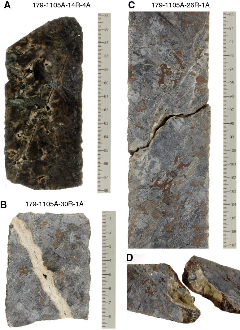
Figure F37. Various metamorphic veins, Hole 1105A.
Further metamorphic vein observations
As previously noted in Pettigrew, Casey, Miller, et al. (1999), calcite veins at 130–150 mbsf are typically open or consist of calcite with well-developed crystal terminations. In the latter case, crystals have grown into open fracture/pore space, resulting in incomplete closure of the fracture and development of vugs in the vein center (Figure F37B–F37D). The presence of calcite-filled vugs and the increase in low-temperature clay veins correlates with the presence of faults and fracture zones in the lower part of the cored section (see Brittle deformation below). The presence of faults and veins indicates fluid flow was active throughout the fracture systems. This interpretation is consistent with downhole logging temperature anomalies measured during Leg 179 at depths of 104–105 and 135–136 mbsf, which indicate active fluid flow through fractures at these depths (Pettigrew, Casey, Miller, et al., 1999).
Brittle deformation
Fracture zones
We identified four fractured zones in Hole 1105A, most of which are characterized by well-developed brecciated zones. The fractured zones occur at 112, 127, 135, and 150 m CCSF with incipient fault breccias at ~25, 86, 105 and 115 m CCSF (Figure F38). Each fractured zone consists of one to four discrete dense anastomosing fracture networks and/or breccias surrounded by a damage zone defined by minor to moderate fracturing (Figure F39A). The two thickest fractured zones (~5 m drilled vertical thickness) occur at 112 and 127 m CCSF and are most likely fault zones. The fractured zones are commonly accompanied by alteration and in some cases the interval includes hydrothermal breccias (e.g., interval 179-1105A-21R-1A, 26–28 cm). The fractured zone at 112 m CCSF has four fault breccias with variable matrix present from 10% to 90%. None of the other fault/fractured zones have identifiable clast/matrix relationships. The fractured zones are consistent with fracture density (Figure F38).
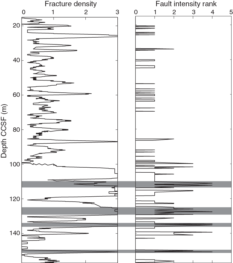
Figure F38. Fracture density increasing with depth and fault rock intensity with depth, Hole 1105A.

Figure F39. A. Fault breccia, Hole 1105A. B. Densely fractured zone.
Hole 1105A has several zones of minor fracturing. The fracturing is mostly manifest in the form of microfractures in plagioclase but can also be exhibited locally by microfractures in pyroxene. These zones of microfractures are commonly associated with Fe-Ti oxide-rich zones, which bracket the most intense fractured zones (Figure F39B).
Discrete fractures
We measured 426 fractures/joints in Hole 1105A. The morphologies of the fractures are dominantly planar (53%), and other fractures are irregular (32%), curved (12%), or stepped (3%). The mean fracture dip is 45° with a standard deviation of 41° (2σ) (Figure F40). Fractures with no vein material and dips <10° are considered drilling induced and were not measured. The distribution of dips is nonrandom compared to a predicted random distribution of fractures sampled with a vertical borehole (see Structural geology in the Expedition 360 methods chapter [MacLeod et al., 2017]), with a discernible skew toward shallower dips. Fractures with steep dips from 80° to 90° seem to cluster at certain depths (e.g., ~60 and ~90 m CCSF).

Figure F40. A. Frequency distribution of fracture dips, Hole 1105A. B. Depth distribution of fracture dip magnitude.
A total of 19% of both planar and irregular fractures are filled or partially filled with vein material; 14 fractures with vein material have slickensides. Two of the slickensides have shear sense indication, both of which are normal. Twelve of the slickensides have slickenlines with a plunge ranging from 16° to 65° with the majority of plunges ranging from 30° to 55°. Slickenlines have moderate to high rakes representing oblique- to dip-slip. In one case (Sample 179-1105A-26R-2, 133 cm), the slickenlines have a rake of 17°, which represents near strike-slip. The slickensides were observed over the entire interval (20–153 m CCSF) but are clustered near 120 m CCSF, which correlates with one of the main fault zones at 127 m CCSF.
Breccias
Two concentrated zones of magmatic breccias were observed at ~25 and ~140 m CCSF. Both zones consist of plagioclase-rich dikes with angular clasts of pyroxene. The pyroxene clasts are often altered to amphibole. The breccias typically form ~10 cm thick discrete zones with sharp boundaries. The zone at ~25 m CCSF consists of two magmatic breccias (intervals 179-1105A-1R-5, 56–66 cm, and 2R-2, 55–55 cm). The zone at ~140 m CCSF consists of four magmatic breccias (intervals 27R-1, 44–55 cm, 27R-1, 110–118 cm, 27R-2, 0–4 cm, and 27R-2, 108–112 cm) (Figure F41A). Two hydrothermal breccias were noted at 85 and 111 m CCSF (intervals 14R-4, 48–68 cm, and 21R-1, 26–38 cm, respectively) and are characterized by alteration phases, usually white mica and altered pyroxene clasts. The hydrothermal breccias have fewer clasts and are less brecciated compared to the magmatic breccias.
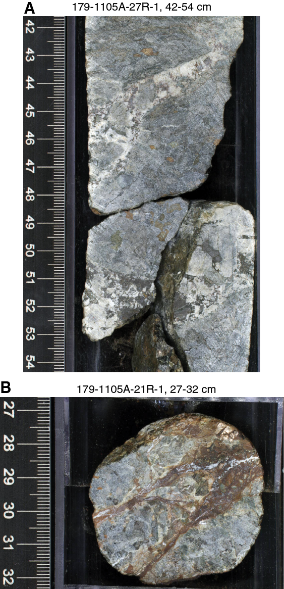
Figure F41. A. Magmatic breccia. B. Hydrothermal breccia.
Microstructures
Gabbroic rocks recovered from Hole 1105A display preserved igneous microstructures, magmatic fabrics, and variably developed crystal-plastic deformation, as reported from macroscopic observations. Because the thin sections from Hole 1105A have been previously described (Pettigrew, Casey, Miller, et al., 1999), the structural geology team focused on a subset of thin sections (41 out of 67) to describe and characterize some of the macroscopic observations. See the Leg 179 Initial Reports volume for supplementary observations (Pettigrew, Casey, Miller, et al., 1999).
Magmatic microstructures
Igneous textures essentially free of crystal-plastic overprint represent 55% of samples observed in the described thin sections. In general, magmatic textures are granular, coarse to medium grained, and hypidiomorphic (Figure F42). Plagioclase is euhedral to subhedral and shows straight to curved grain boundaries, igneous and tapered twins, undulose extinction, and thin fractures (Figure F42A–F42B, F42D). Olivine crystals are anhedral, display straight to curved boundaries, and commonly have undulose extinction. Fracture density in olivine is variable. Clinopyroxene crystals, which are poikilitic, are commonly not deformed and are subhedral to anhedral (Figure F42A). Oxides are anhedral and form interstitial pods with several crystals of ilmenite and magnetite (Figure F42E). Magmatic foliations may be difficult to identify because of coarse grain size, but when visible the fabric is weakly oriented (Figure F42B) and defined by the SPO of plagioclase, pyroxene, and locally olivine (Figure F42B–F42D). As observed in hand sample, relationships between magmatic fabrics and magmatic contacts may be observed. For example, Sample 179-1105A-13R-1, 24–26 cm, shows a coarse-grained gabbro with a moderate magmatic fabric with a weak crystal-plastic overprint, in contact with a fine-grained gabbro, and the fabric is subparallel to the contact (Figure F42C).

Figure F42. Magmatic and incipient crystal-plastic microstructures, Hole 1105A.
Transition from magmatic to crystal-plastic deformation
The onset of intracrystalline plasticity is mainly observed in coarse plagioclase, clinopyroxene, and olivine grains with subhedral to anhedral shapes and in curved contacts with oxide pods. Incipient recrystallization, commonly localized at grain boundaries and/or at contacts between the phases, is restricted to fine grains mantling coarse plagioclase porphyroclasts. Fe-Ti oxide pods commonly surround mafic porphyroclasts and/or neoblasts. The Fe-Ti oxide pods fill interstitial space and conform to any silicate grain boundary with vermicular shapes (Figures F42F, F43A–F43B). These features are classified as incipient recrystallization microstructures and are not pervasive enough to overprint the primary magmatic foliation; elongated porphyroclasts of plagioclase grains with limited recrystallization and undeformed clinopyroxene crystals can define a shape-preferred magmatic orientation.
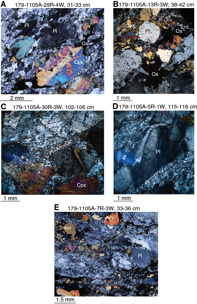
Figure F43. Crystal-plastic microstructures, Hole 1105A.
Crystal-plastic structures
Deformation intensity ranges between weakly foliated and ultramylonitic. Weak crystalline plasticity can be seen in coarse plagioclase grains with curved to straight boundaries and in coarse clinopyroxene clasts rimmed by Fe-Ti oxides (Figure F43A–F43B); the SPO of clinopyroxene defines a solid-state foliation. Fe-Ti oxides commonly occur as large patches or pods rimming plagioclase and clinopyroxene porphyroclasts (Figure F43B). This fabric type dominates throughout Hole 1105A and is classified as CPF Rank 3 (porphyroclastic).
Progressive deformation results in partial recrystallization of plagioclase into fine-grained, locally polygonal aggregates (Figure F43C). The recrystallized grains may form bands that rim coarse grains (Figure F43C) or may be localized within cracks that crosscut coarse plagioclase porphyroclasts (Figure F43D). Fine-grained bands commonly consist of a mixture of recrystallized plagioclase + clinopyroxene + oxides + alteration products (typically amphibole); grains filling cracks are essentially composed of plagioclase and are strain free.
Mylonite fabrics (CPF Rank 4) are mainly characterized by nearly complete to complete recrystallization of plagioclase into a fine-grained matrix that contains recrystallized clinopyroxene, Fe-Ti oxides, and alteration products (Figure F43E). Relict clinopyroxene and plagioclase porphyroclasts display irregular undulose extinction, and subgrain boundaries are commonly straight to curved. Subgrains are commonly the same size as recrystallized products. Tapered twins are commonly observed in plagioclase, and bending of cleavage planes may be locally observed in clinopyroxene porphyroclasts.
Ultramylonites are marked by complete recrystallization of all phases into a fine-grained foliated aggregate. Grain size is significantly reduced, resulting in mixtures of plagioclase, clinopyroxene, oxides, and alteration products with small homogeneous grain size.
Oxide gabbros and crystal-plastic deformation
Fe-Ti oxides have been observed within crystal-plastically deformed rocks at Atlantis Bank in Hole 735B (Dick et al., 2000; Natland, 2002) and in Hole 1105A (Pettigrew, Casey, Miller, et al., 1999). As increasing Fe-Ti oxide contents result in increasing magnetic susceptibility (see Petrophysics), we use the magnetic susceptibility measured during Expedition 360 to trace the presence of Fe-Ti oxides and compare with the CPF intensity throughout Hole 1105A (Figure F44). Peaks in magnetic susceptibility are defined by >10 point measurements of ≥104 IU. There are 12 occurrences of CPFs that are mylonitic or ultramylonitic in Hole 1105A, 10 of which show a correlation with peaks in magnetic susceptibility. There are a total of 30 magnetic susceptibility peaks, 80% of them correlated with some level of crystal-plastic deformation (≥1), indicating a possible positive correlation between the presence of Fe-Ti oxides and deformation in Hole 1105A.

Figure F44. CPF intensity and magnetic susceptibility, Hole 1105A.
A total of 44 out of 67 (~65%) shipboard thin sections from Hole 1105A, redescribed during Expedition 360, have Fe-Ti oxides. The Fe-Ti oxides are either related to alteration processes, especially olivine alteration, filling interstitial spaces between silicate cumulates or are found in discrete bands as well as vein networks. Of the thin sections, 55% have some level of crystal-plastic deformation; 25% of the thin sections have a deformation intensity rank >3 (i.e., porphyroclastic and greater deformation). Weakly crystal-plastically deformed rocks commonly contain Fe-Ti oxides in pressure shadows associated to mafic phases, especially pyroxene, and the Fe-Ti oxide pods are elongated parallel to the foliation (Figure F45). Fe-Ti oxide pods commonly surround neoblasts of pyroxene and plagioclase. Intensely deformed rocks have Fe-Ti oxides that range from distributed, especially in mylonites (Sample 179-1105A-5R-1, 144–147 cm), to larger pods near pyroxene (Sample 22R-1, 103–106 cm). Samples with the highest amount of Fe-Ti oxides display a magmatic fabric with a weak crystal-plastic overprint and are typically coarse grained (e.g., Sample 11R-2, 129–133 cm; Figure F45A). In some examples, the Fe-Ti oxide abundance is high enough to have disrupted the silicate cumulate framework (Sample 7R-3, 33–36 cm).
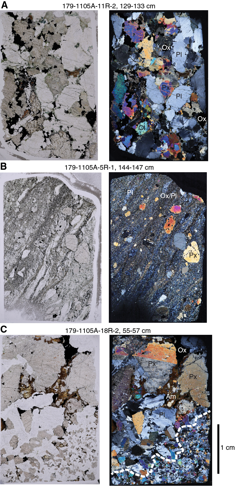
Figure F45. Whole thin section photographs, Hole 1105A.
Seven of the nine contacts in thin section, mostly between fine- and coarse-grained gabbro, have Fe-Ti oxides (~77%) (Figure F45C). The coarser-grained gabbro is often weakly crystal-plastically deformed with limited amounts of recrystallized plagioclase mantling porphyroclasts. The contact is typically diffuse with larger phenocrysts entrained within the fine-grained rock. However, the contact boundary itself is not sheared.
Summary
The gabbros from Hole 1105A display a series of magmatic contacts, magmatic fabrics, CPFs, alteration veins, brittle deformation, and associated crosscutting relationships suggestive of a down-temperature continuum of deformation in an oceanic core complex. The main observations and conclusions of our structural analysis of Hole 1105A are as follows:
- Fine-grained gabbros intruded coarse-grained gabbros and subsequently underwent at least two phases of high-temperature deformation.
- Felsic veins make up ~1% of the recovery.
- Several intervals lack magmatic fabrics or CPFs, particularly shallower than 80 m CCSF.
- Magmatic fabrics are weakly developed overall. They typically occur and are better developed in the finer-grained rocks.
- CPFs occur in highly deformed discrete intervals shallower than ~80 m CCSF and in thicker broader gneissic porphyroclastic zones at greater depths.
- Clay and amphibole veins do not strongly overlap with depth; the clay veins commonly crosscut the CPFs.
- We identified four fractured zones, two of which are faults, and all occur deeper than 80 m CCSF.
- There is a positive correlation between peaks in magnetic susceptibility (directly correlated to abundant Fe-Ti oxides) and crystal-plastic deformation.
Pettigrew, Casey, Miller, et al. (1999) documented and presented most of the main observations made during this study, including that thicker zones of crystal-plastic deformation occurred at the bottom of the core.
The Pettigrew, Casey, Miller, et al. (1999) report of structural observations from Hole 1105A was augmented by postexpedition work by Casey et al. (2007). Whereas Pettigrew, Casey, Miller, et al. (1999) identified the main structures (e.g., CPFs) and reported their depth, the orientation and intensity of many structures were not reported. The Expedition 360 structural geology team completed detailed logging of structural features, providing structural logs of orientation and intensity that can now be compared with Holes 735B and U1473A and other ODP/Integrated Ocean Drilling Program/IODP holes. The following is a summary of the main differences and similarities between Holes 1105A and 735B:
- The top 15–80 m CCSF of Hole 1105A has very little crystal-plastic deformation compared to the equivalent depth interval of Hole 735B.
- Both Holes 735B and 1105A reveal a continuum of magmatism and shearing with at least two generations of both magmatic intrusion and ductile shearing.
- Zones of fracturing are absent from the upper 80 m of both Holes 1105A and 735B.
- Hole 735B has more amphibole veins that crosscut CPFs compared to Hole 1105A.
The CPF intensities downhole presented here are consistent with Shipboard Scientific Party (1999a), who show the thickest section of crystal-plastic deformation is in the bottom half of the hole (their figure F26). Casey et al. (2007) plotted the intensity of deformation downhole using a modified intensity scale from 0 to 8 based on petrographic observations. They suggest that there is more crystal-plastic deformation in the upper part of Hole 1105A than observed by Pettigrew, Casey, Miller, et al. (1999), which is confirmed by the Expedition 360 results (Figure F46). The simplest explanation for this discrepancy between the Leg 179 Initial Reports volume and Casey et al. (2007) is that thin seams/regions of crystal-plastically deformed plagioclase around undeformed clinopyroxene are more easily recognizable in thin section than in hand sample. We suggest that observations at both scales should be used for logging and plotting downhole variation.
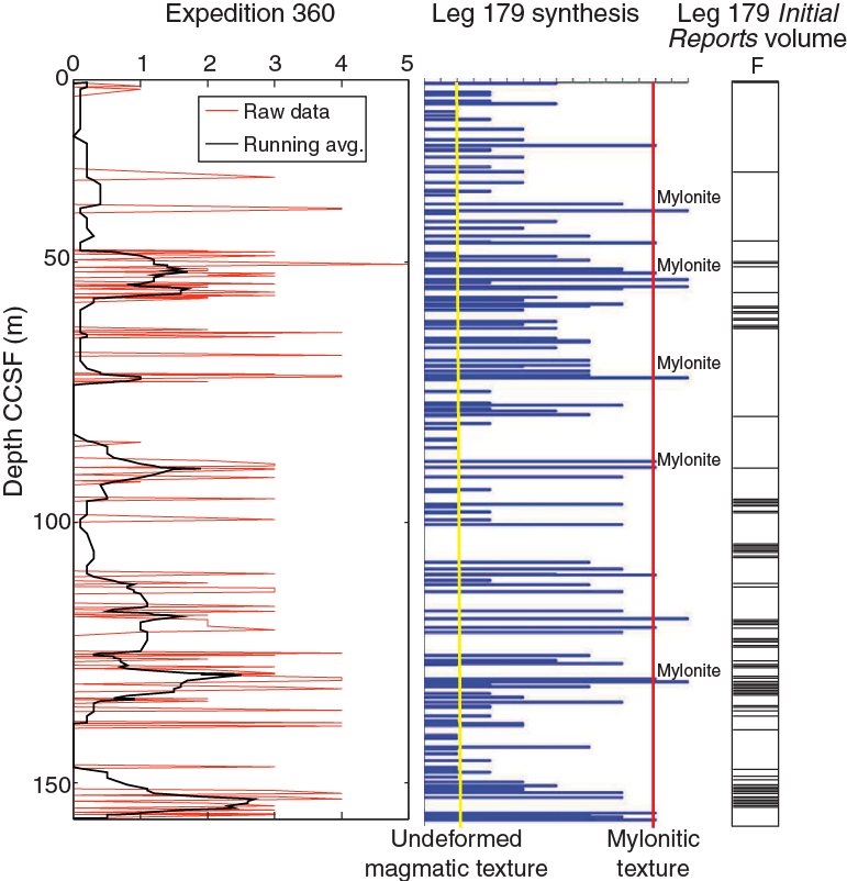
Figure F46. Comparison between Expedition 360, Leg 179 synthesis, and Leg 179 Initial Reports volume crystal-plastic intensity, Hole 1105A.
Based on the observations presented here, we suggest that the lower oceanic crust of Atlantis Bank resulted from the complex interplay of magmatic intrusion and deformation. Magmatic fabrics are often weakly overprinted by CPF indicative of a continuum from high-temperature magmatic flow to solid-state flow. We interpret at least two intrusive events and two high-temperature shearing events together with lower temperature brittle overprint and faulting. Stronger crystal-plastic deformation shallower than 80 m CCSF is typically discrete, whereas at greater depth the deformation is more distributed. The distribution of fractured zones is similar to the distribution of crystal-plastic deformation, as the fractured zones are most abundant and widespread deeper than 80 m CCSF. However, some of the fundamental conclusions that can be drawn from these observations, specifically that the thickest zones of deformation are deeper in the cored interval and the mean dip of CPFs is 35°, are not consistent with the simple concept of a shallowly dipping detachment shear zone near the seafloor. This is in contrast to Hole 735B, where the deformation intensity is very high near the seafloor and decreases with depth. Alternatively, the CPFs may still represent deformation related to the detachment shear zone but are indicative of a broader damage zone that records high-temperature magmatism and deformation at the spreading ridge.
Paleomagnetism
Archive section half remanence data
Remanence measurements were made on archive section half pieces recovered during Leg 179 by rotary core barrel (RCB) coring in Hole 1105A. These pieces were previously subjected to alternating field (AF) demagnetization during Leg 179 to a maximum peak field of 20 mT (Pettigrew, Casey, Miller, et al., 1999). However, only natural remanent magnetization (NRM) directions and intensities from these previous shipboard analyses were reported numerically in the Leg 179 Initial Reports volume and no filtering of the data was conducted.
During Expedition 360, these archive section halves were remeasured after storage of the samples in ODP/Integrated Ocean Drilling Program/IODP core repositories for 17 y. Initial magnetizations therefore do not represent NRM values but instead are a measurement of the 20 mT treatment step from Leg 179 plus any acquired viscous magnetic overprint. During Expedition 360, the archive section halves were AF demagnetized to higher levels (20, 25, 30, 35, 40, and 50 mT) to recover higher coercivity components of magnetization. A limited set of archive section halves was treated at higher fields (60 and 80 mT), but this yielded no further information of value and was therefore discontinued to reduce measurement times and increase core flow through the superconducting rock magnetometer (SRM). Remanence was measured every 2 cm, and the resulting data were filtered to reject measurement points within 4 cm of piece ends. Pieces <8 cm long were removed from the tray during demagnetization and measurement. A list of these pieces is provided in PALEOMAG in Supplementary material.
The same filtering was then applied to the NRM data from Leg 179. In addition, point magnetic susceptibility (MSP) data obtained from archive section halves during Expedition 360 were filtered to preserve only data corresponding to the intervals where remanence measurements were made.
For the purpose of characterization based on bulk magnetic parameters, the lithologies recovered from Hole 1105A are grouped into three categories based on oxide content (Figure F47): (1) gabbros with no visible oxide content (including gabbro and olivine gabbro), with a geometric mean NRM intensity of 0.56 A/m (range = 0.016–10.1 A/m; N = 808) and a geometric mean low-field susceptibility of 374 instrument units (IU) (range = 6–8891 IU; N = 281); (2) disseminated-oxide and oxide-bearing gabbros (i.e., with <5% oxides including disseminated-oxide and oxide-bearing gabbro and olivine gabbro), with a geometric mean NRM intensity of 1.03 A/m (range = 0.071–7.93 A/m; N = 291) and a geometric mean susceptibility of 1022 IU (range = 43–9633 IU; N = 468); and (3) oxide gabbros (i.e., with >5% oxides including oxide gabbro and oxide olivine gabbro), with a geometric mean NRM intensity of 2.56 A/m (range = 0.014–14.3 A/m; N = 479) and a geometric mean susceptibility of 1884 IU (range = 27–9967 IU; N = 912). Range and mean susceptibility values are likely underestimated because of an instrument artifact that “wraps” data ≥10,000 IU due to limited dynamic range and returns lower values by subtracting 10,000 IU (see Petrophysics in the Expedition 360 methods chapter [MacLeod et al., 2017]).
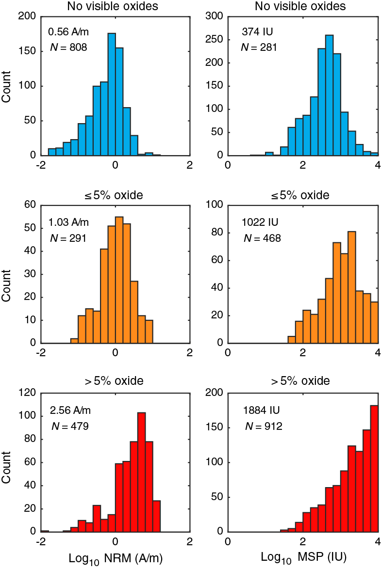
Figure F47. NRM intensity and low-field magnetic susceptibility for each of three simplified lithologic groups, Hole 1105A.
Histogram distributions of NRM and susceptibility are shown in Figure F47. Data demonstrate that with increasing oxide content the oxide gabbro (>5% oxides) and oxide-bearing gabbro (<5% oxides) have progressively higher NRM intensities and susceptibilities than the gabbro and olivine gabbro. However, all groups have wide ranges of NRM and susceptibility that overlap considerably.
AF demagnetization of archive section halves during Expedition 360 generated a data set consisting of 2679 individual orthogonal vector plots requiring principal component analysis (PCA) (see PALEOMAG in Supplementary material). Virtually all sampling points have positive inclinations, indicating that the drilled interval at the site carries a reversed magnetization, consistent with interpretation of marine magnetic anomalies (Allerton and Tivey, 2001). Visual inspection of orthogonal vector plots revealed three types of AF demagnetization behavior (Figures F48, F49):
- Samples with linear demagnetization trajectories toward the origin (Figure F48A–F48C), representing the highest quality data.
- Samples with linear demagnetization trajectories broadly directed toward the origin but that miss the origin by varying amounts (Figure F48D–F48F).
- Samples with demagnetization trajectories that are not directed toward the origin (Figure F49A) or with nonlinear trajectories (Figure F49B).
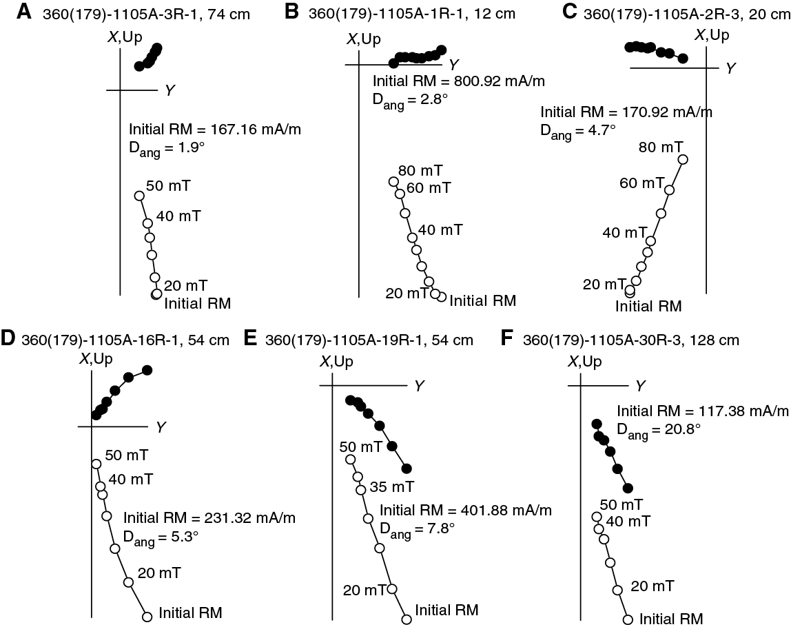
Figure F48. A–F. AF demagnetization of archive section halves, Hole 1105A.
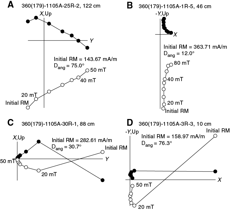
Figure F49. A–D. AF demagnetization of archive section halves, Hole 1105A.
Large vertical drilling-induced components that are often observed in Integrated Ocean Drilling Program hard rock samples (e.g., Expedition 304/305 Scientists, 2006; Teagle, Ildefonse, Blum, and the Expedition 335 Scientists, 2012; Gillis, Snow, Klaus, and the Expedition 345 Scientists, 2014) are not evident in these data, indicating that previous AF demagnetization to 20 mT during Leg 179 was effective in removing such components or that significant drilling-induced magnetizations were not acquired during Leg 179 operations. However, some archive-half pieces show major changes in remanence direction between the initial measurement made during Expedition 360 and the subsequent 20 mT AF demagnetization step (Figure F49C–F49D). This indicates that some samples have acquired a spurious low-coercivity viscous overprint during storage in the ODP/Integrated Ocean Drilling Program/IODP core repositories, which is largely removed by a second treatment at 20 mT.
The data filtering approach adopted during Expedition 360 (see Paleomagnetism in the Expedition 360 methods chapter [MacLeod et al., 2017]) allows rapid analysis of extensive archive-half data sets and robust identification of the highest quality demagnetization data (i.e., statistically acceptable linear components that decay to the origin from the most stable samples). The resulting quality-filtered reduced data set for Hole 1105A consists of 1248 remanence determinations. Figure F50 shows the downhole variation of PCA inclinations and demonstrates that filtering was effective at selecting a well-constrained set of remanence inclinations (compare Figure F50B–F50C). Application of the systematic quantitative criteria (outlined in Paleomagnetism in the Expedition 360 methods chapter [MacLeod et al., 2017]) results in rejection of the majority of outlying data (Figure F50B). Only four outliers from the main distribution remain after quality filtering (at ~58 and ~99.5 m CCSF; Figure F50C). These samples are dominated by large low-coercivity components with anomalous directions (probably acquired during sample storage) and are therefore excluded from subsequent calculation of mean inclinations.
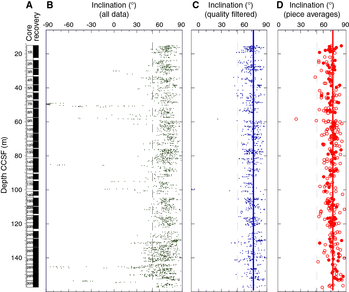
Figure F50. Summary of archive section half remanent inclination data, Hole 1105A.
Finally, mean directions of magnetization have been calculated for archive-half pieces with multiple measurement points after quality filtering (Figure F50D; Table T4). These mean directions are accompanied by Fisherian statistics (Fisher, 1953) for pieces containing ≥4 measurements.
Table T4. Piece-averaged remanence data, Hole 1105A. Download table in .csv format.
Inclination-only statistics
Estimates for mean inclination and the dispersion parameter (k) (Fisher, 1953) were determined using the maximum likelihood estimator of McFadden and Reid (1982), which is minimally biased for steep inclinations (Table T5). The algorithm used takes the absolute value of negative inclinations, assuming negative values represent a reversed field state. In the present case, highly divergent values with shallow negative inclinations will therefore be included as shallow positive inclinations. The resulting mean inclination based on all data passing selection criteria and excluding the outliers at 58 and 99.5 m CCSF (see above) results in a mean of 72.3° (k = 55.3; N = 1244). Piece-averaged data have a mean inclination of 72.5° (k = 49.9; N = 346), or 72.7° (k = 97.0; N = 110) for those pieces containing ≥4 measurement points that pass quality filtering. This latter value is considered to represent the most robust estimate of the true mean inclination.
Table T5. Inclination-only mean statistics, Hole 1105A and previously published analyses of samples from Atlantis Bank. Download table in .csv format.
This inclination is in good agreement with results made on discrete samples from other ODP/Integrated Ocean Drilling Program/IODP expeditions to Atlantis Bank (Table T5), including ODP Leg 118 Hole 735B (Kikawa and Pariso, 1991), ODP Leg 176 Hole 735B (Shipboard Scientific Party, 1999b), and Leg 179 Hole 1105A (Gopala Rao and Krishna, 2002). It is also in approximate agreement with results from seabed core drill samples from Atlantis Bank (Allerton and Tivey, 2001). Compared to the expected dipole inclination of 51.3°, the results imply a minimum rotation of ~20° since the acquisition of magnetization.
Petrophysics
The physical properties of the gabbroic rocks recovered in Hole 1105A during Leg 179 were characterized during Expedition 360 through a set of measurements on section halves and section half pieces as described in Petrophysics in the Expedition 360 methods chapter (MacLeod et al., 2017). We measured MSP with the Section Half Multisensor Logger (SHMSL) and thermal conductivity on discrete samples. The rock names reported in data tables in this section correspond to the primary lithologies assigned by the Expedition 360 igneous petrology team.
Magnetic susceptibility
During Expedition 360, magnetic susceptibility was measured on archive section halves using the Bartington MS2E probe (see Petrophysics in the Expedition 360 methods chapter [MacLeod et al., 2017]). MS2E point measurements were compared with pass-through data obtained on whole-round sections during Leg 179 with a MS2C pass-through coil. Raw data were filtered following the procedure described in Petrophysics in the Expedition 360 methods chapter (MacLeod et al., 2017). Filtered and raw data are available in PETROPHYS in Supplementary material (available in both Microsoft Excel and ASCII). Two filtering passes were applied to Hole 1105A magnetic susceptibility data, as a test of the edge-offset specified in the algorithm. Pass 1 filtered out Expedition 360 section half data obtained <1 cm from each apparent piece edge and Leg 179 whole-round data <4 cm from an edge. Pass 2 filtered out data <2 cm and <5 cm from apparent edges for section half (Expedition 360) and whole-round data (Leg 179), respectively. The mean magnetic susceptibility of rocks recovered in Hole 1105A is 1810 IU (Pass 2 filter), although this is biased low because of the wrap-around limitation of the system for values >104 IU. Whole-round measurements made during Leg 179 agree overall with the MSP measurements obtained during Expedition 360, although they differ in some local intervals (Figure F51).
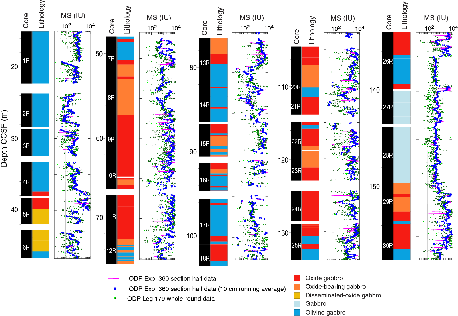
Figure F51. Summary of magnetic susceptibility measurements, Hole 1105A.
Several intervals have susceptibility much greater than the average value for Hole 1105A (Figure F51). Susceptibility is relatively low at the top of the hole and rises more than 3000 IU in interval 179-1105A-4R-1, 12 cm, through 5R-2, 12 cm (37.34–39.88 m CCSF). Interval 7R-1, 35 cm, through 26R-2, 104 cm (48.15–136.41 m CCSF), displays continuously high susceptibility. Susceptibility is then again low toward the bottom of the hole except in intervals 27R-1, 63 cm, through 27R-1 104 cm (139.33–139.74 m CCSF), and 29R-2, 15 cm, through 30R-3, 20 cm (149.82–156.30 m CCSF). These intervals correspond to intervals with a higher abundance of magnetite in oxide or oxide-bearing (olivine) gabbro. Some magnetic susceptibility peaks are quite narrow; several checks against core mineralogy confirmed that narrow oxide seams or blebs were the source of such signals.
Thermal conductivity
Thermal conductivity was measured on 28 gabbroic rock samples taken at irregularly spaced intervals along Hole 1105A (Table T6; Figure F52). Measured values range from 1.80 to 2.98 W/(m·K), with an average of 2.16 W/(m·K). Thermal conductivity results are generally averages of 6 measurements for each sample (10 measurements in two samples). In Sample 179-1105A-7R-2A, 118–136 cm (Piece 8), heat reflection at the piece edge was suspected; therefore, several runs with lower heat source settings (3.5, 3.0, and 2.5 W/m) were conducted (for a total of 32 single measurements), with no significant variation of the measured thermal conductivity. Standard deviations of each mean value are <1% for all samples except the oxide olivine gabbro Sample 7R-2, 118–136 cm (Piece 8), for which the standard deviation of the mean conductivity is 1.20% (Table T6).
Table T6. Thermal conductivity measurements run on Hole 1105A samples during Expedition 360. Download table in .csv format.
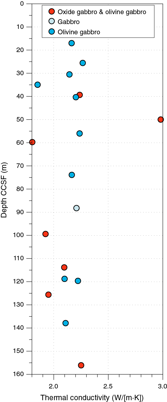
Figure F52. Downhole summary of Expedition 360 thermal conductivity measurements, Hole 1105A.
References
Allerton, S., and Tivey, M.A., 2001. Magnetic polarity structure of the lower oceanic crust. Geophysical Research Letters, 28(3):423–426. http://dx.doi.org/10.1029/2000GL008493
Bloomer, S.H., Meyer, P.S., Dick, H.J.B., Ozawa, K., and Natland, J.H., 1991. Textural and mineralogic variations in gabbroic rocks from Hole 735B. In Von Herzen, R.P., Robinson, P.T., et al., Proceedings of the Ocean Drilling Program, Scientific Results, 118: College Station, TX (Ocean Drilling Program), 21–39. http://dx.doi.org/10.2973/odp.proc.sr.118.136.199
Casey, J.F., Banerji, D., and Zarian, P., 2007. Leg 179 synthesis: geochemistry, stratigraphy, and structure of gabbroic rocks drilled in ODP Hole 1105A, Southwest Indian Ridge. In Casey, J.F., and Miller, D.J. (Eds.), Proceedings of the Ocean Drilling Program, Scientific Results, 179: College Station, TX (Ocean Drilling Program), 1–125. http://dx.doi.org/10.2973/odp.proc.sr.179.001.2007
Coogan, L.A., Wilson, R.N., Gillis, K.M., and MacLeod, C.J., 2001. Near-solidus evolution of oceanic gabbros: insights from amphibole geochemistry. Geochimica et Cosmochimica Acta, 65(23):4339–4357. http://dx.doi.org/10.1016/S0016-7037(01)00714-1
Czamanske, G.K., and Moore, J.G., 1977. Composition and phase chemistry of sulfide globules in basalt from the Mid-Atlantic Ridge rift valley near 37°N lat. Geological Society of America Bulletin, 88(4):587–599. http://dx.doi.org/10.1130/0016-7606(1977)88<587:CAPCOS>2.0.CO;2
Dick, H.J.B., Natland, J.H., Miller, D.J., et al., 1999. Proceedings of the Ocean Drilling Program, Initial Reports, 176: College Station, TX (Ocean Drilling Program). http://dx.doi.org/10.2973/odp.proc.ir.176.1999
Dick, H.J.B., Natland, J.H., Alt, J.C., Bach, W., Bideau, D., Gee, J.S., Haggas, S., Hertogen, J.G.H., Hirth, G., Holm, P.M., Ildefonse, B., Iturrino, G.J., John, B.E., Kelley, D.S., Kikawa, E., Kingdon, A., LeRoux, P.J., Maeda, J., Meyer, P.S., Miller, D.J., Naslund, H.R., Niu, Y.-L., Robinson, P.T., Snow, J., Stephen, R.A., Trimby, P.W., Worm, H.-U., and Yoshinobu, A., 2000. A long in situ section of the lower ocean crust: results of ODP Leg 176 drilling at the Southwest Indian Ridge. Earth and Planetary Science Letters, 179(1):31–51. http://dx.doi.org/10.1016/S0012-821X(00)00102-3
Expedition 304/305 Scientists, 2006. Methods. In Blackman, D.K., Ildefonse, B., John, B.E., Ohara, Y., Miller, D.J., MacLeod, C.J., and the Expedition 304/305 Scientists, Proceedings of the Integrated Ocean Drilling Program, 304/305: College Station, TX (Integrated Ocean Drilling Program Management International, Inc.). http://dx.doi.org/10.2204/iodp.proc.304305.102.2006
Fisher, R.A., 1953. Dispersion on a sphere. Proceedings of the Royal Society of London, Series A, 217:295–305.
Gillis, K.M., Snow, J.E., Klaus, A., and the Expedition 345 Scientists, 2014. Proceedings of the Integrated Ocean Drilling Program, 345: College Station, TX (Integrated Ocean Drilling Program). http://dx.doi.org/10.2204/iodp.proc.345.2014
Gopala Rao, D., and Krishna, K.S., 2002. Magnetic rock properties of the gabbros from the ODP Drill Hole 1105 A of the Atlantis Bank, Southwest Indian Ridge. Journal of Earth System Science, 111(4):467–481. http://dx.doi.org/10.1007/BF02702059
Grove, T.L., Kinzler, R.J., and Bryan, W.B., 1992. Fractionation of mid-ocean ridge basalt (MORB). In Morgan, J.P., Blackman, D.K., and Sinton, J.M. (Eds.), Mantle Flow and Melt Generation at Mid-Ocean Ridges. Geophysical Monograph, 71:281–310. http://dx.doi.org/10.1029/GM071p0281
Kikawa, E., and Pariso, J.E., 1991. Magnetic properties of gabbros from Hole 735B, Southwest Indian Ridge. In Von Herzen, R.P., Robinson, P.T., et al., Proceedings of the Ocean Drilling Program, Scientific Results, 118: College Station, TX (Ocean Drilling Program), 285–307. http://dx.doi.org/10.2973/odp.proc.sr.118.148.1991
Koepke, J., Feig, S., and Snow, J., 2005. Late stage magmatic evolution of oceanic gabbros as a result of hydrous partial melting: evidence from the Ocean Drilling Program (ODP) Leg 153 drilling at the Mid-Atlantic Ridge. Geochemistry, Geophysics, Geosystems, 6(2):Q02001. http://dx.doi.org/10.1029/2004GC000805
MacLeod, C.J., Dick, H.J.B., Blum, P., Abe, N., Blackman, D.K., Bowles, J.A., Cheadle, M.J., Cho, K., Ciążela, J., Deans, J.R., Edgcomb, V.P., Ferrando, C., France, L., Ghosh, B., Ildefonse, B.M., Kendrick, M.A., Koepke, J.H., Leong, J.A.M., Liu, C., Ma, Q., Morishita, T., Morris, A., Natland, J.H., Nozaka, T., Pluemper, O., Sanfilippo, A., Sylvan, J.B., Tivey, M.A., Tribuzio, R., and Viegas, L.G.F., 2017. Expedition 360 methods. In MacLeod, C.J., Dick, H.J.B., Blum, P., and the Expedition 360 Scientists, Southwest Indian Ridge Lower Crust and Moho. Proceedings of the International Ocean Discovery Program, 360: College Station, TX (International Ocean Discovery Program). http://dx.doi.org/10.14379/iodp.proc.360.102.2017
Maeda, J., Naslund, H.R., Jang, Y.D., Kikawa, E., Tajima, T., and Blackburn, W.H., 2002. High-temperature fluid migration within oceanic Layer 3 gabbros, Hole 735B, Southwest Indian Ridge: implications for the magmatic-hydrothermal transition at slow-spreading mid-ocean ridges. In Natland, J.H., Dick, H.J.B., Miller, D.J., and Von Herzen, R.P. (Eds.), Proceedings of the Ocean Drilling Program, Scientific Results, 176: College Station, TX (Ocean Drilling Program), 1–56. http://dx.doi.org/10.2973/odp.proc.sr.176.004.2002
McFadden, P.L., and Reid, A.B., 1982. Analysis of paleomagnetic inclination data. Geophysical Journal of the Royal Astronomical Society, 69(2):307–319. http://dx.doi.org/10.1111/j.1365-246X.1982.tb04950.x
Meyer, P.S., Dick, H.J.B., and Thompson, G., 1989. Cumulate gabbros from the Southwest Indian Ridge, 54°S–7°16′E: implications for magmatic processes at a slow spreading ridge. Contributions to Mineralogy and Petrology, 103(1):44–63. http://dx.doi.org/10.1007/BF00371364
Natland, J.H., 2002. Magnetic susceptibility as an index of the lithology and composition of gabbros, ODP Leg 176, Hole 735B, Southwest Indian Ridge. In Natland, J.H., Dick, H.J.B., Miller, D.J., and Von Herzen, R.P. (Eds.), Proceedings of the Ocean Drilling Program, Scientific Results, 176: College Station, TX (Ocean Drilling Program), 1–69. http://dx.doi.org/10.2973/odp.proc.sr.176.008.2002
Natland, J.H., Meyer, P.S., Dick, H.J.B., and Bloomer, S.H., 1991. Magmatic oxides and sulfides in gabbroic rocks from Hole 735B and the later development of the liquid line of descent. In Von Herzen, R.P., Robinson, P.T., et al., Proceedings of the Ocean Drilling Program, Scientific Results, 118: College Station, TX (Ocean Drilling Program), 75–111. http://dx.doi.org/10.2973/odp.proc.sr.118.163.1991
Ozawa, K., Meyer, P.S., and Bloomer, S.H., 1991. Mineralogy and textures of iron-titanium oxide gabbros and associated olivine gabbros from Hole 735B. In Von Herzen, R.P., Robinson, P.T., et al., Proceedings of the Ocean Drilling Program, Scientific Results, 118: College Station, TX (Ocean Drilling Program), 41–73. http://dx.doi.org/10.2973/odp.proc.sr.118.125.1991
Perfit, M.R., and Fornari, D.J., 1983. Geochemical studies of abyssal lavas recovered by DSRV Alvin from eastern Galapagos Rift, Inca Transform, and Ecuador Rift, 2. Phase chemistry and crystallization history. Journal of Geophysical Research, 88(B12):10530–10550. http://dx.doi.org/10.1029/JB088iB12p10530
Pettigrew, T.L., Casey, J.F., Miller, D.J., et al., 1999. Proceedings of the Ocean Drilling Program, Initial Reports, 179: College Station, TX (Ocean Drilling Program). http://dx.doi.org/10.2973/odp.proc.ir.179.1999
Shipboard Scientific Party, 1999a. Hammer drill site (1104 and 1106) and Site 1105. In Pettigrew, T.L., Casey, J.F., Miller, D.J., et al. Proceedings of the Ocean Drilling Program, Initial Reports, 179: College Station, TX (Ocean Drilling Program), 1–183. http://dx.doi.org/10.2973/odp.proc.ir.179.104.1999
Shipboard Scientific Party, 1999b. Site 735. In Dick, H.J.B., Natland, J.H., Miller, D.J., et al., Proceedings of the Ocean Drilling Program, Initial Reports, 176: College Station, TX (Ocean Drilling Program), 1–314. http://dx.doi.org/10.2973/odp.proc.ir.176.103.1999
Teagle, D.A.H., Ildefonse, B., Blum, P., and the Expedition 335 Scientists, 2012. Proceedings of the Integrated Ocean Drilling Program, 335: Tokyo (Integrated Ocean Drilling Program Management International, Inc.). http://dx.doi.org/10.2204/iodp.proc.335.2012
1 MacLeod, C.J., Dick, H.J.B., Blum, P., Abe, N., Blackman, D.K., Bowles, J.A., Cheadle, M.J., Cho, K., Ciążela, J., Deans, J.R., Edgcomb, V.P., Ferrando, C., France, L., Ghosh, B., Ildefonse, B.M., Kendrick, M.A., Koepke, J.H., Leong, J.A.M., Liu, C., Ma, Q., Morishita, T., Morris, A., Natland, J.H., Nozaka, T., Pluemper, O., Sanfilippo, A., Sylvan, J.B., Tivey, M.A., Tribuzio, R., and Viegas, L.G.F., 2017. Hole 1105A redescription. In MacLeod, C.J., Dick, H.J.B., Blum, P., and the Expedition 360 Scientists, Southwest Indian Ridge Lower Crust and Moho. Proceedings of the International Ocean Discovery Program, 360: College Station, TX (International Ocean Discovery Program). http://dx.doi.org/10.14379/iodp.proc.360.104.2017
- F1. A. Lithostratigraphic variations in Hole 1105A as redescribed during Expedition 360. B. Hole 1105A compared to Hole 735B.
- F2. Variations of mineral mode with depth plotted by interval, Hole 1105A.
- F3. Correlations between plagioclase and oxide modes, Hole 1105A.
- F4. Boundary between olivine-bearing oxide gabbro and olivine-bearing gabbro, Hole 1105A.
- F5. Boundary between coarse-grained olivine-bearing oxide gabbro and fine-grained oxide-bearing olivine gabbro, Hole 1105A.
- F6. Variations in contact type with depth, Hole 1105A.
- F7. Variations in mean grain sizes of plagioclase, clinopyroxene, and olivine with depth plotted by interval, Hole 1105A.
- F8. Correlations of mean grain size between plagioclase and clinopyroxene and olivine, Hole 1105A.
- F9. Medium-grained olivine gabbro, coarse-grained olivine gabbro, and pegmatitic olivine gabbro, Hole 1105A.
- F10. Magmatic felsic vein in gabbro, Hole 1105A.
- F11. Olivine-plagioclase-clinopyroxene and oxide-plagioclase-clinopyroxene ternary diagrams, Hole 1105A.
- F12. A. Olivine, plagioclase, and clinopyroxene. B. Clinopyroxene and olivine inclusions. C. Small equant plagioclase inclusions. D. Amoeboidal olivine. E. Blebs. F. Deformed plagioclase.
- F13. A, B. Olivine rimmed, Hole 1105A. C. Clinopyroxene overgrown. D. Clinopyroxene rimmed by intergrowth.
- F14. Magmatic oxides and related minerals in thin section, Hole 1105A.
- F15. Downhole alteration intensity of primary igneous phases and occurrence of vein filling minerals, Hole 1105A.
- F16. Clinopyroxene alteration, Hole 1105A.
- F17. Olivine and plagioclase alteration, Hole 1105A.
- F18. Types of amphibole veins in gabbros, Hole 1105A.
- F19. A, B. Whole thin section images of mylonitic olivine gabbro.
- F20. Aggregates dominated by brown hornblende.
- F21. Cataclastic intervals with brownish/whitish veins and brown clay pseudomorphs, Hole 1105A.
- F22. Magmatic veins, Hole 1105A.
- F23. A. Frequency dip distribution of magmatic veins, Hole 1105A. B. Depth dip distribution of magmatic veins.
- F24. Sharp structural contact between a largely undeformed olivine gabbro and a crystal-plastically deformed olivine-bearing oxide gabbro.
- F25. A. Frequency dip distribution of magmatic contacts, Hole 1105A. B. Depth dip distribution of magmatic contacts.
- F26. Relatively gradational contact between mostly undeformed fine-grained intrusive olivine- and oxide-bearing gabbro and slightly crystal-plastically deformed olivine-bearing oxide gabbro.
- F27. Different contact styles between intruding microgabbros and their coarser-grained gabbro hosts.
- F28. High-temperature deformation crosscutting relationships, Hole 1105A.
- F29. A. Histogram of magmatic fabric intensity, Hole 1105A. B. Variation of magmatic fabric intensity with depth.
- F30. A. Frequency distribution of magmatic fabric dips, Hole 1105A. B. Depth distribution of magmatic fabric and magmatic contact dips.
- F31. CPF intensity with depth, Hole 1105A.
- F32. A. Frequency distribution of CPF dips, Hole 1105A. B. Depth distribution of CPF dips.
- F33. Typical aspect of ductile shear zones with sharp boundaries, Hole 1105A.
- F34. High-temperature solid-state foliation, Hole 1105A.
- F35. Metamorphic vein density and vein fill proportion with depth, Hole 1105A.
- F36. Dip of amphibole, clay, and other veins, Hole 1105A.
- F37. Various metamorphic veins, Hole 1105A.
- F38. Fracture density increasing with depth and fault rock intensity with depth, Hole 1105A.
- F39. A. Fault breccia, Hole 1105A. B. Densely fractured zone.
- F40. A. Frequency distribution of fracture dips, Hole 1105A. B. Depth distribution of fracture dip magnitude.
- F41. A. Magmatic breccia. B. Hydrothermal breccia.
- F42. Magmatic and incipient crystal-plastic microstructures, Hole 1105A.
- F43. Crystal-plastic microstructures, Hole 1105A.
- F44. CPF intensity and magnetic susceptibility, Hole 1105A.
- F45. Whole thin section photographs, Hole 1105A.
- F46. Comparison between Expedition 360, Leg 179 synthesis, and Leg 179 Initial Reports volume crystal-plastic intensity, Hole 1105A.
- F47. NRM intensity and low-field magnetic susceptibility for each of three simplified lithologic groups, Hole 1105A.
- F48. A–F. AF demagnetization of archive section halves, Hole 1105A.
- F49. A–D. AF demagnetization of archive section halves, Hole 1105A.
- F50. Summary of archive section half remanent inclination data, Hole 1105A.
- F51. Summary of magnetic susceptibility measurements, Hole 1105A.
- F52. Downhole summary of Expedition 360 thermal conductivity measurements, Hole 1105A.
- T1. Summary of lithology thickness and proportion, Hole 1105A.
- T2. Primary igneous lithologies (intervals), Hole 1105A.
- T3. List of redescribed Hole 1105A thin sections.
- T4. Piece-averaged remanence data, Hole 1105A.
- T5. Inclination-only mean statistics, Hole 1105A and previously published analyses of samples from Atlantis Bank.
- T6. Thermal conductivity measurements run on Hole 1105A samples during Expedition 360.