Morgan, J., Gulick, S., Mellett, C.L., Green, S.L., and the Expedition 364 Scientists
Proceedings of the International Ocean Discovery Program Volume 364
publications.iodp.org
https://doi.org/10.14379/iodp.proc.364.104.2017

Site M0077: Open Hole1
S. Gulick, J. Morgan, C.L. Mellett, S.L. Green, T. Bralower, E. Chenot, G. Christeson, P. Claeys, C. Cockell, M.J.L. Coolen, L. Ferrière, C. Gebhardt, K. Goto, H. Jones, D. Kring, J. Lofi, C. Lowery, R. Ocampo-Torres, L. Perez-Cruz, A.E. Pickersgill, M. Poelchau, A. Rae, C. Rasmussen, M. Rebolledo-Vieyra, U. Riller, H. Sato, J. Smit, S. Tikoo, N. Tomioka, J. Urrutia-Fucugauchi, M. Whalen, A. Wittmann, K. Yamaguchi, L. Xiao, and W. Zylberman2
Keywords: International Ocean Discovery Program, IODP, International Continental Scientific Drilling Program, ICDP, L/B Myrtle, Mission Specific Platform, Expedition 364, Site M0077, Hole M0077A, Gulf of México, Yucatán shelf, Chicxulub, impact crater, crater modification, multi-ring basin, peak ring, uplifted continental crust, impact melt rock, planar deformation features, Cretaceous/Paleogene boundary, PETM, K-Pg boundary, Cretaceous-Paleogene mass extinction, shock metamorphism, carbon isotope excursions, hydrothermal, geomagnetic reversal, shatter cone, ejecta, suevite, granitoid, pelagic limestone, tsunamite
MS 364-104: Published 30 December 2017
Introduction
The upper part of Hole M0077A, the Open Hole interval, was drilled without coring to maximize the potential to reach the target drilling depth (see Introduction in the Expedition 364 methods chapter [Gulick et al., 2017a]). A rotary drill was used for open-hole drilling from the seabed to 505.7 m drilling depth below seafloor (DSF). Attempts to recover drilling chips from this open-hole section were largely unsuccessful due to loss of drilling fluid into the formation. However, some lithologic and biostratigraphic data were recovered and will be used to support the geological interpretation of the wireline logging data. The following sections detail the data and measurements from this interval.
Operations
After arriving on station at Hole M0077A, drilling operations commenced on 8 April 2016. At 0330 h (all times are Central Daylight Time), the conductor pipe reached the seabed, and preparations for open-hole drilling were made. An open-hole assembly with a 12¼ inch tricone bit was utilized. At 1342 h, the drill reached the seabed and drilling began. Drill cuttings were collected at regular intervals from drilling fluid returned to deck via the temporary guide casing. At 1550 h, drilling reached 5.5 m DSF, and the pipe was tripped out to start running the 9⅝ inch casing into the hole. At 0045 h on 9 April, the conductor casing was in place, and cement was injected into the hole and allowed to set. At 1500 h, the casing was cut to length, and the drilling fluid diverter system was set up on the drill floor. Following this, a 7⅞ inch tricone bit was run in to the top of the cement, and open-hole drilling commenced with a target depth of 500 m DSF.
Drilling continued on 10 April at a rate of approximately 8 m/h. Between 82 and 101 m DSF, drilling fluid circulation was lost, and following attempts to adjust drilling fluid composition to counteract this loss, the decision to cement the hole was made. Following cementation, 24 h was allowed for the cement to cure. At 0000 h on 12 April, pipe was run in, and at 0435 h, drilling of the cement plug at 82 m DSF commenced. Despite another loss of circulation in this section, drilling progressed, reaching 229 m DSF by 2400 h. On 12 April, the supply vessel visited the L/B Myrtle, delivering European Consortium for Ocean Research Drilling (ECORD) Science Operator (ESO) personnel, logging engineers, food, and fuel.
Drilling continued on 13 April, achieving the target depth for open-hole drilling at 503.6 m DSF at 2153 h. The remainder of April 13 was spent pulling out of the hole and preparing for downhole logging operations and vertical seismic profile (VSP) operations.
At 0955 h on 14 April, test firing of the air gun occurred, accompanied by appropriate marine mammal and protected species observation. At 1015 h, the supply vessel arrived, and ESO personnel and members of the Science Party joined the L/B Myrtle.
At 1300 h, wireline logging commenced. For a summary of the operations and acquisition parameters for each tool or tool string run, see Downhole logging in the Expedition 364 methods chapter (Gulick et al., 2017a). By 1600 h, all tools were recovered to deck to ensure VSP operations were carried out in daylight. VSP operations continued until 2330 h and were accompanied by appropriate marine mammal and protected species observations. The VSP equipment was recovered at 0300 h on 15 April, and set up for wireline logging commenced. Logging operations continued until 1400 h on 16 April.
Following these operations, the drill string was tripped and casing was run into the hole. Running casing continued until 2400 h, during which difficulties connecting the casing were noted. Downhole logging was carried out at 0215 h on 16 April to assess the condition of the casing. Based on these results, it was considered possible to continue casing by connecting two pipes downhole, and the full depth of the open hole was cased by 2000 h. Following this, the hole was cemented and left to cure.
On 17 April, logging started at 0650 h for operational support to check the pipe connection. At 0723 h, while the tool string was going down the hole, the cable tension loosened at ~269 m wireline log depth below seafloor (WSF), and the tool was brought back to the surface. Fresh cement was observed coating the bottom of the tool, indicating cement was present downhole at a shallower depth than anticipated. At 1300 h, running of pipe commenced to remove cement and start coring. The core barrel became stuck at 1820 h at 307 m DSF. After attempts to free the core barrel, the string was tripped at 2000 h. Pipe tripping continued until 0040 h on 18 April, when the bottom-hole assembly (BHA) was recovered to deck. Upon examination, it was observed that the rubber bung used to cap the cement was caught in the BHA and was the obstruction preventing further progress. After changing out the BHA, pipe was run back into the hole. However, an obstruction was again encountered at the same depth (307 m DSF) near to where the casing was reconnected, indicating potential misalignment of the casing. At 0825 h, it was necessary to once again trip the pipe to add a reaming bit to the BHA so milling and reaming could be carried out to advance through the casing. Running in of pipe recommenced at 1500 h, and at 0710 h on 19 April, the milling and reaming assembly reached the base of the hole and was tripped out to make preparations for coring.
Lithology
No core was recovered from the uppermost ~503 m DSF because this interval was open-hole drilled. However, some cuttings were returned to the drill floor through the drilling fluid recycling system. Cuttings returned from the uppermost 80 m of the formations contained shallow-water limestone with echinoid spines, coral fragments, and other forms of carbonate debris. At 35 m DSF, the drilling coordinator noted that there was very little weight on the drill bit. Therefore, the formation was likely to be soft/weak in strength. At approximately 79 m DSF, there was a total loss of drilling fluid into the surrounding formation, suggesting that a cavity or highly permeable formation is present at this depth.
From 81 to ~503 m DSF, seawater was circulated and no cuttings were returned.
At the base of the open-hole drilling (503.6 m DSF), mud from the formation was retrieved from the drill string upon recovery to deck. This mud is firm, foraminifer-bearing olive-green clay.
Biostratigraphy
Cuttings were examined for the uppermost 80 m, and an additional sample at 503.6 m DSF was collected from mud found on a tool run to the bottom of the hole after casing. The upper 80 m of cuttings are of indeterminate age and are indicative of a shallow-water carbonate environment. The sample collected at 503.6 m DSF is middle Eocene in age and indicative of a normal marine setting with bathyal water depths (~500–700 m). Semiquantitative abundance counts for this sample are included in Biostratigraphy in the Site M0077: Post-Impact Sedimentary Rocks chapter (Gulick et al., 2017b).
Shallow-water carbonate
A representative subsample of cuttings samples collected from the shaker table during open-hole drilling was analyzed for foraminiferal biostratigraphy in the upper 80 m of Hole M0077A. These samples all contain coarse fragments of indurated limestone containing echinoid spines, coral fragments, bivalve fragments, and other indistinct shallow-water carbonate debris. Benthic foraminifers are very rare and poorly preserved and are mainly represented by specimens of Planulina, Lenticulina, and Cibicidoides. No planktic foraminifers were present.
Around 80 m DSF, the drillers began circulating seawater only to compensate for increased drilling fluid loss to the formation, so no cuttings were returned for the interval between 80 and 503.6 m DSF. See Operations for more discussion.
Eocene
At 503.6 m DSF, a magnet was run down the hole to retrieve bits of broken metal ahead of the BHA; the magnet returned to the surface coated with chunks of firm olive-green clay. At this point, the hole was cased from the seafloor to 503.6 m DSF, so this mud was interpreted to come from the bottom of the hole. After sieving (and complete disaggregation), this “cuttings” sample yielded a moderately well preserved assemblage of planktic foraminifers indicative of a middle Eocene age, particularly the planispiral Planoglobanomalina pseudoalgeriana (base in Zone E6). Generally, the assemblage is dominated by Pseudohastigerina wilcoxensis. Benthic foraminifers are also relatively common (estimated ~30% of the total assemblage) and are mainly represented by common Uvigerina, Bulimina, and Bolivina, together interpreted to represent an upper bathyal water depth.
Nannofossils indicate that this sample belongs to Zone CP12 based on the occurrence of Discoaster sublodoensis, or possibly Zone CP13 based on a single specimen of a very early form of Chiasmolithus gigas, the lowest occurrence of which defines the base of Subzone CP13b. Additional significant species in this sample include Chiasmolithus grandis and Triquetrorhabdulus inversus.
Downhole logging
Downhole logging measurements were conducted during the first logging session, from ~503 m WSF to the pipe entrance at ~20 m WSF (see Downhole logging in the Expedition 364 methods chapter [Gulick et al., 2017a]). Here we provide a description of the downhole data sets collected and their general characteristics. A few detailed examples are given that highlight some interesting aspects of the logs.
Wireline logs
From 0 to ~503 m WSF, the hole was very stable, and borehole conditions varied from poor to very good below ~450 m WSF, where the borehole diameter was almost in gauge with the drill bit diameter. As a consequence of the borehole conditions, wireline log data quality was moderate (Figure F1). The sonic log (VP) and the acoustic borehole images (ABIs) were affected by the borehole conditions in the upper 450 m WSF, whereas measurements such as gamma ray were generally less sensitive to the variable borehole conditions. Gamma ray logs from the various tool strings and runs aligned well, and only a few small postacquisition depth-shift adjustments (less than 10 cm) were required between the various passes.
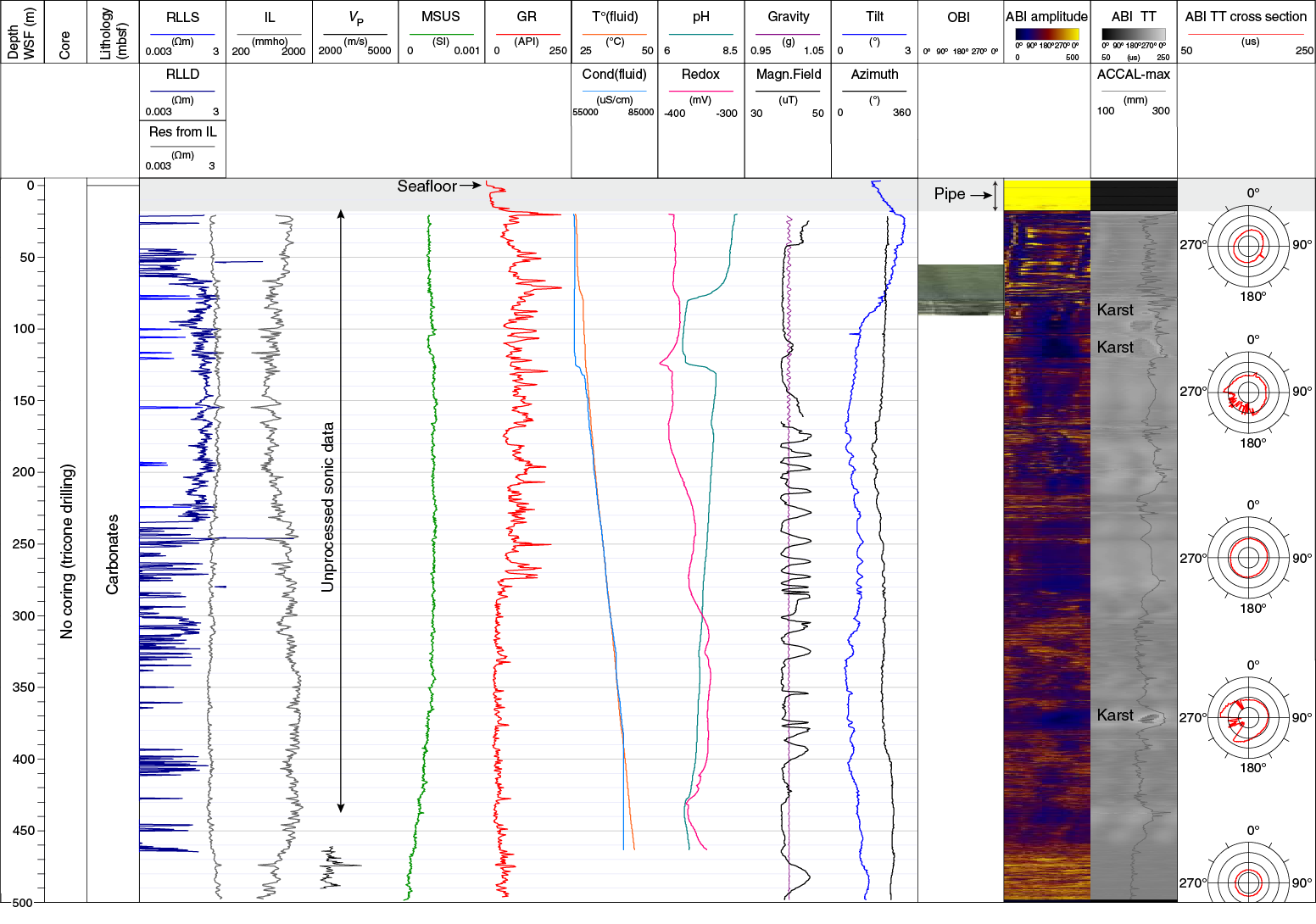
Figure F1. Wireline downhole log data.
The wireline seafloor was identified at 33.94 m below the rig table (mbrt) on the through-casing gamma ray log by the abrupt change in gamma ray count at the water/sediment boundary (mudline). Discrepancy between the drilling seafloor depth (34.2 mbrt) and the wireline seafloor depth (33.94 mbrt) was small. In the upper 20 m WSF, gamma ray values were lower than downhole as a result of the attenuation of the signal through pipe and casing.
In the upper 503 m, Hole M0077A wireline logs are characterized by high- to low-amplitude variability on a several-meter scale (Figure F1). At the ~500 m scale, the resistivity (RLLS and RLLD) and conductivity (IL) logs are anticorrelated, as expected. The resistivity logs should be used for qualitative studies only, as a result of the high conductivity of the formation (see Downhole logging in the Expedition 364 methods chapter [Gulick et al., 2017a]) and the large borehole diameter (>20 cm). The quality of the conductivity log is higher. Spikes in resistivity often correlate with high-amplitude intervals on the ABI image, suggesting they are related to changes in material competence (hard layers associated with high resistivities and high ABI amplitudes). The magnetic susceptibility signal (MSUS) is weak, as expected in carbonate formations, and shows low variability. A downhole decreasing trend is observed below ~340 m WSF. The borehole fluid temperature (T°fluid) ranged from 26°C below the casing to 43°C at 463 m WSF. Because the measurement was acquired shortly after drilling, this temperature likely reflects a minimum value for the in situ temperature of the formation. The borehole fluid temperature, conductivity (Condfluid), and redox logs show downhole increasing trends, whereas pH decreases downhole. Fluid parameter logs can only be used qualitatively because they were acquired shortly after drilling operations. A pronounced shift in their trend between 77 and 125 m WSF, over an interval in which the borehole diameter is enlarged, possibly relates to the presence of karsts. These karsts are well identified in the ABI images from 77.5 to 86.5 m WSF as zones of low amplitude (dark blue in Figure F2) and increased traveltimes. Karsts appear dark in color on the optical borehole image (OBI). Above ~80 m WSF, the OBIs do not display any visible geological features because of the presence of cement/mud cake in the borehole. However, structures are visible on the ABI image, likely because the acoustic signal penetrates deep enough to image borehole wall structures.
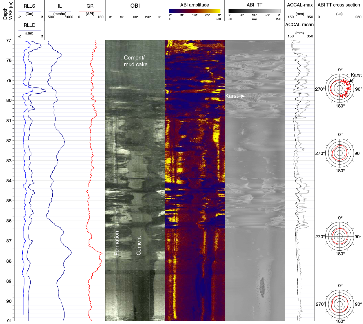
Figure F2. Wireline downhole log data 77–81 m WSF.
At the ~500 m scale, the ABI images are of moderate quality due to the large width of the borehole and its irregular shape, as indicated by the maximum acoustic caliper (ACCAL-max), which shows that the diameter ranged from 18 to 28 cm. Traveltime cross sections at several depths illustrate the changes in borehole shape, from very irregular in the upper 100 m to almost perfectly circular in the lowest 40 m. Locally, an ellipsoidal shape was also observed (e.g., at ~50 m WSF in Figure F1 and ~82.5 m WSF in Figure F2).
The character of the logs changes downhole with a major step in the base level at ~274 m WSF, as is clearly observed on the gamma ray log. In the upper 274 m WSF, the gamma ray signal typically ranges from 60 to 220 API, with a mean value around 100 API. In this interval, a series of spikes was observed correlating either with low or high resistivity values. At 274 m WSF, the gamma ray counts become less variable and decrease to ~30 API. At ~462 m WSF, a slight increasing downhole trend in gamma ray is observed, whereas conductivity decreases from ~1500 to ~500 mmho. The borehole shape appears to be circular and in gauge over this interval, as evidenced by the acoustic caliper. As a result of the borehole conditions, a processed sonic velocity log (VP) is only available below 460 m WSF, with a mean P-wave velocity around 2200 m/s. A spike in velocity reaching ~3800 m/s was observed at 474.5 m WSF, correlating well with a low in the conductivity log and a high-amplitude horizon on the ABI image (Figure F3). Below ~475 m WSF, the acoustic caliper shows some enlarged zones that correlate with low amplitudes on the ABI image and increases in gamma ray counts. These layers likely correspond to intervals where soft materials were partly washed out during drilling (Figure F3).
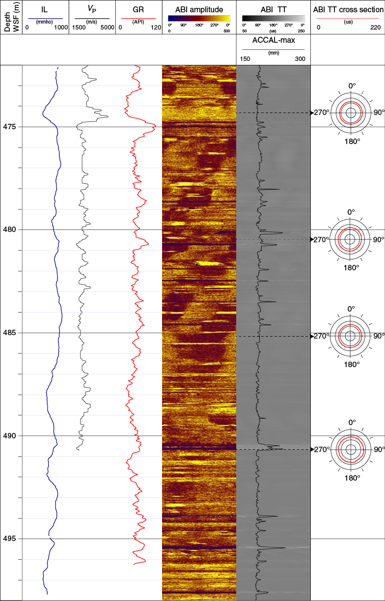
Figure F3. Wireline downhole log data 472–478 m WSF.
Vertical seismic profile
The three-component VSP collected from ~500.00–47.50 m WSF was of generally good quality. The vertical component of the VSP shows a broad-spectrum waveform up to 350 Hz with dominant frequencies at 25, 64, and 104 Hz (Figure F4A).

Figure F4. Vertical VSP components.
First-arrival traveltimes (Figure F4B) were picked on the first trough, and then a moving-window algorithm was used to determine the change in P-wave velocity with depth (Figure F4C). The signal contains reverberations at several discrete depth sections (approximately 120, 185, 210, 270, and 370 m WSF), which are potentially due to poor receiver coupling. Tube waves were observed at 185 m WSF. The amplitude of the reverberations is strongest at ~270 m WSF, at a location where there is a sharp change in P-wave velocity from 2285 to 2567 m/s (Figure F4C). A strong reflection that originates from below the logged zone is indicated in Figure F4A as “R.”
First and secondary arrivals in the radial and azimuthal horizontal components are mostly coherent (Figure F5). The azimuthal component arrivals are more coherent than the radial, and both are noisier than the vertical component at the same recording depths. Tube waves were observed at 270 and 145 m WSF. The horizontal component also shows probable S-wave arrivals.
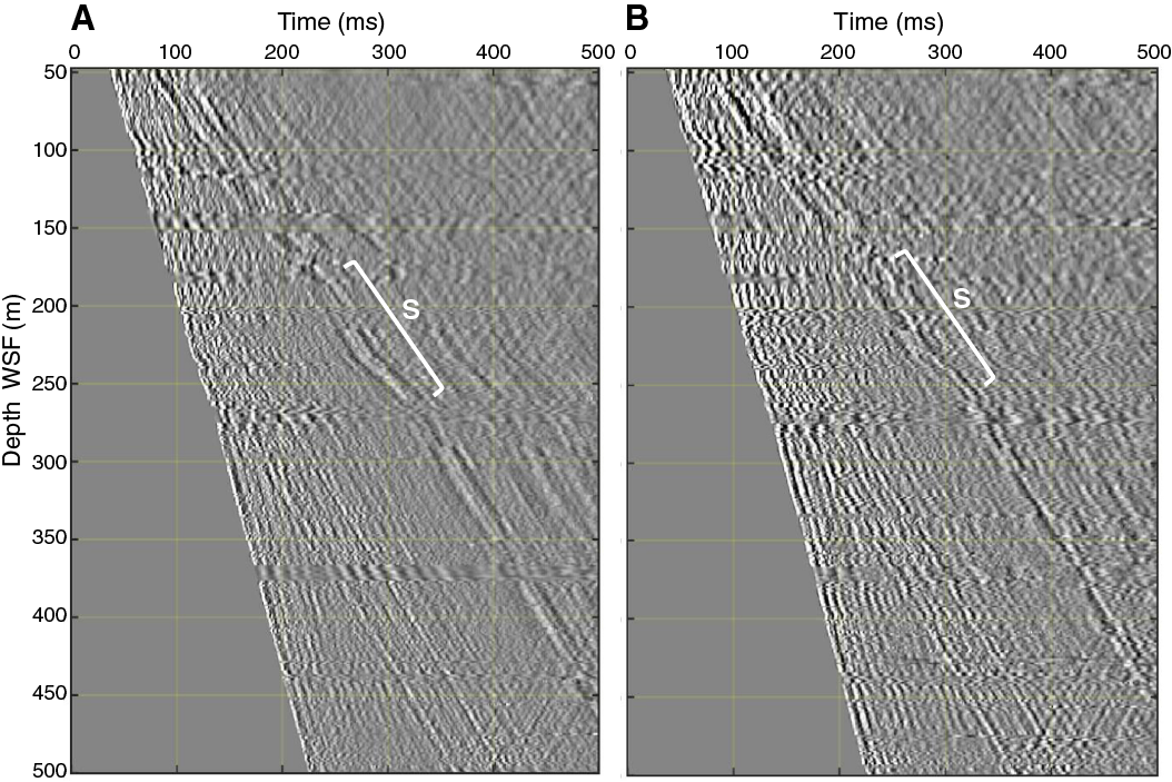
Figure F5. Horizontal VSP components.
References
Gulick, S., Morgan, J., Mellett, C.L., Green, S.L., Bralower, T., Chenot, E., Christeson, G., Claeys, P., Cockell, C., Coolen, M.J.L., Ferrière, L., Gebhardt, C., Goto, K., Jones, H., Kring, D., Lofi, J., Lowery, C., Ocampo-Torres, R., Perez-Cruz, L., Pickersgill, A.E., Poelchau, M., Rae, A., Rasmussen, C., Rebdolledo-Vieyra, M., Riller, U., Sato, H., Smit, J., Tikoo, S., Tomioka, N., Urrutia Fucugauchi, J., Whalen, M., Wittmann, A., Yamagachi, K., Xiao, L., and Zylberman, W., 2017a. Expedition 364 methods. In Morgan, J., Gulick, S., Mellett, C.L., Green, S.L., and the Expedition 364 Scientists, Chicxulub: Drilling the K-Pg Impact Crater. Proceedings of the International Ocean Discovery Program, 364: College Station, TX (International Ocean Discovery Program). https://doi.org/10.14379/iodp.proc.364.102.2017
Gulick, S., Morgan, J., Mellett, C.L., Green, S.L., Bralower, T., Chenot, E., Christeson, G., Claeys, P., Cockell, C., Coolen, M.J.L., Ferrière, L., Gebhardt, C., Goto, K., Jones, H., Kring, D., Lofi, J., Lowery, C., Ocampo-Torres, R., Perez-Cruz, L., Pickersgill, A.E., Poelchau, M., Rae, A., Rasmussen, C., Rebdolledo-Vieyra, M., Riller, U., Sato, H., Smit, J., Tikoo, S., Tomioka, N., Urrutia Fucugauchi, J., Whalen, M., Wittmann, A., Yamagachi, K., Xiao, L., and Zylberman, W., 2017b. Site M0077: Post-Impact Sedimentary Rocks. In Morgan, J., Gulick, S., Mellett, C.L., Green, S.L., and the Expedition 364 Scientists, Chicxulub: Drilling the K-Pg Impact Crater. Proceedings of the International Ocean Discovery Program, 364: College Station, TX (International Ocean Discovery Program). https://doi.org/10.14379/iodp.proc.364.105.2017
1 Gulick, S., Morgan, J., Mellett, C.L., Green, S.L., Bralower, T., Chenot, E., Christeson, G., Claeys, P., Cockell, C., Coolen, M.J.L., Ferrière, L., Gebhardt, C., Goto, K., Jones, H., Kring, D., Lofi, J., Lowery, C., Ocampo-Torres, R., Perez-Cruz, L., Pickersgill, A.E., Poelchau, M., Rae, A., Rasmussen, C., Rebolledo-Vieyra, M., Riller, U., Sato, H., Smit, J., Tikoo, S., Tomioka, N., Urrutia- Fucugauchi, J., Whalen, M., Wittmann, A., Yamaguchi, K., Xiao, L., and Zylberman, W., 2017. Site M0077: Open Hole. In Morgan, J., Gulick, S., Mellett, C.L., Green, S.L., and the Expedition 364 Scientists, Chicxulub: Drilling the K-Pg Impact Crater. Proceedings of the International Ocean Discovery Program, 364: College Station, TX (International Ocean Discovery Program). https://doi.org/10.14379/iodp.proc.364.104.2017
2 Expedition 364 Scientists’ addresses.
This work is distributed under the Creative Commons Attribution 4.0 International (CC BY 4.0) license. 