Pecher, I.A., Barnes, P.M., LeVay, L.J., and the Expedition 372A Scientists
Proceedings of the International Ocean Discovery Program Volume 372A
publications.iodp.org

https://doi.org/10.14379/iodp.proc.372A.101.2019
Expedition 372A summary1
P.M. Barnes, I.A. Pecher, L.J. LeVay, S.M. Bourlange, M.M.Y. Brunet, S. Cardona, M.B. Clennell, A.E. Cook, M.P. Crundwell, B. Dugan, J. Elger, D. Gamboa, A. Georgiopoulou, A. Greve, S. Han, K.U. Heeschen, G. Hu, G.Y. Kim, H. Kitajima, H. Koge, X. Li, K.S. Machado, D.D. McNamara, G.F. Moore, J.J. Mountjoy, M.A. Nole, S. Owari, M. Paganoni, K.E. Petronotis, P.S. Rose, E.J. Screaton, U. Shankar, C.L. Shepherd, M.E. Torres, M.B. Underwood, X. Wang, A.D. Woodhouse, and H.-Y. Wu2
Keywords: International Ocean Discovery Program, IODP, JOIDES Resolution, Expedition 372, Site U1517, Hikurangi margin, Tuaheni Landslide Complex, Tuaheni Basin, New Zealand, gas hydrates, slope stability, fluid flow, mass transport deposits, logging while drilling
MS 372A-101: Published 5 May 2019
Abstract
International Ocean Discovery Program (IODP) Expedition 372 combined two research topics: actively deforming gas hydrate–bearing landslides (IODP Proposal 841-APL) and slow slip events on subduction faults (IODP Proposal 781A-Full). This expedition included a coring and logging-while-drilling (LWD) program for Proposal 841-APL and a LWD program for Proposal 781A-Full. The coring and observatory placement for Proposal 781A-Full were completed during Expedition 375. The Expedition 372A Proceedings volume focuses only on the results related to Proposal 841-APL. The results of the Hikurangi margin drilling are found in the Expedition 372B/375 Proceedings volume.
Gas hydrates have long been suspected of being involved in seafloor failure. Not much evidence, however, has been found to date for gas hydrate–related submarine landslides. Solid, ice-like gas hydrate in sediment pores is generally thought to increase seafloor strength, which is confirmed by a number of laboratory measurements. Dissociation of gas hydrate to water and overpressured gas, on the other hand, may weaken and destabilize sediments, potentially causing submarine landslides.
The Tuaheni Landslide Complex (TLC) on the Hikurangi margin shows evidence for active, creeping deformation. Intriguingly, the landward edge of creeping coincides with the pinch-out of the base of gas hydrate stability on the seafloor. We therefore proposed that gas hydrate may be involved in creep-like deformation and presented several hypotheses that may link gas hydrates to slow deformation. Alternatively, creeping may not be related to gas hydrates but instead be caused by repeated pressure pulses or linked to earthquake-related liquefaction.
Plans for Expedition 372A included a coring and LWD program to test our landslide hypotheses. Because of weather-related downtime, the gas hydrate–related program was reduced and we focused on a set of experiments at Site U1517 in the creeping part of the TLC. We conducted a LWD and coring program to 205 m below the seafloor through the TLC and the gas hydrate stability zone, followed by temperature and pressure tool deployments.
Introduction
Gas hydrates and submarine landslides
Submarine landslides constitute a significant geohazard and modify seafloor morphology (Mulder and Cochonat, 1996). Although progress has been made in studying their causes (Solheim et al., 2005), the processes that control the evolution of submarine slides are still only partially understood.
It is generally thought that submarine slides occur as single catastrophic events leading to mobilization and downslope transport of source material (Mulder and Cochonat, 1996). The submarine Tuaheni Landslide Complex (TLC) east of New Zealand’s North Island, however, exhibits features typical of active, slow-moving terrestrial earthflows that appear to be creeping rather than failing in single events (Mountjoy et al., 2009). Such creeping behavior is observed on shore in mudslides (or earthflows) in weak clay-bearing rock (Baum et al., 2003) and in rock glaciers in ice-bound sediments (Martin and Whalley, 1987). At the TLC, the onset of creeping appears to be linked to the feather edge of gas hydrate stability (FEGHS) where the base of gas hydrate stability (BGHS) pinches out at the seafloor (Mountjoy et al., 2014b). Based on the curvature of bottom-simulating reflectors (BSRs) in the study area and BSR pinch-outs in the vicinity of the slides (Chiswell, 2005; Pecher et al., 2005, 2008), the FEGHS is predicted to occur in water depths between 585 and 640 m, which coincides with the upper limit of creeping interpreted from structural and geomorphic data.
At the FEGHS, gas hydrates, seafloor failure, and ocean change are critically intertwined (Phrampus and Hornbach, 2012). Because gas hydrate is known to strengthen sediments in short-term deformation tests, seafloor destabilization has been linked to hydrate dissociation, although there is no solid evidence for this process. We suggest that the presence of gas hydrate itself may be implicated in creeping during long-term seafloor deformation.
Background
Tectonic setting
At the northern Hikurangi margin, the Pacific plate subducts beneath eastern North Island, New Zealand, at a rate of 4.5–5.5 cm/y (Wallace et al., 2004; Figure F1). The oceanic subducting plate includes the Hikurangi Plateau, a rough-crust, seamount-studded large igneous province of Cretaceous age (120–90 Ma). The plateau is overlain by a Cenozoic to Mesozoic sedimentary sequence that thickens from ~1 to 1.5 km at the northern Hikurangi margin and thickens to >5 km at the southern Hikurangi margin, south of ~40°S. Thus, the northern Hikurangi margin is relatively sediment starved. This part of the margin is characterized by a mixed mode of spatially varying tectonic accretion and frontal tectonic erosion associated with subducting seamounts (Lewis et al., 1998; Collot et al., 2001; Pedley et al., 2010; Barker et al., 2009, 2018). The past subduction of seamounts may have an effect on fluid pressures at the plate interface (Bell et al., 2010; Ellis et al., 2015). Fluid expulsion, potentially related to subduction of seamounts, has been implicated in observed thermal anomalies that disturb the gas hydrate stability field near the TLC (e.g., Pecher et al., 2017).
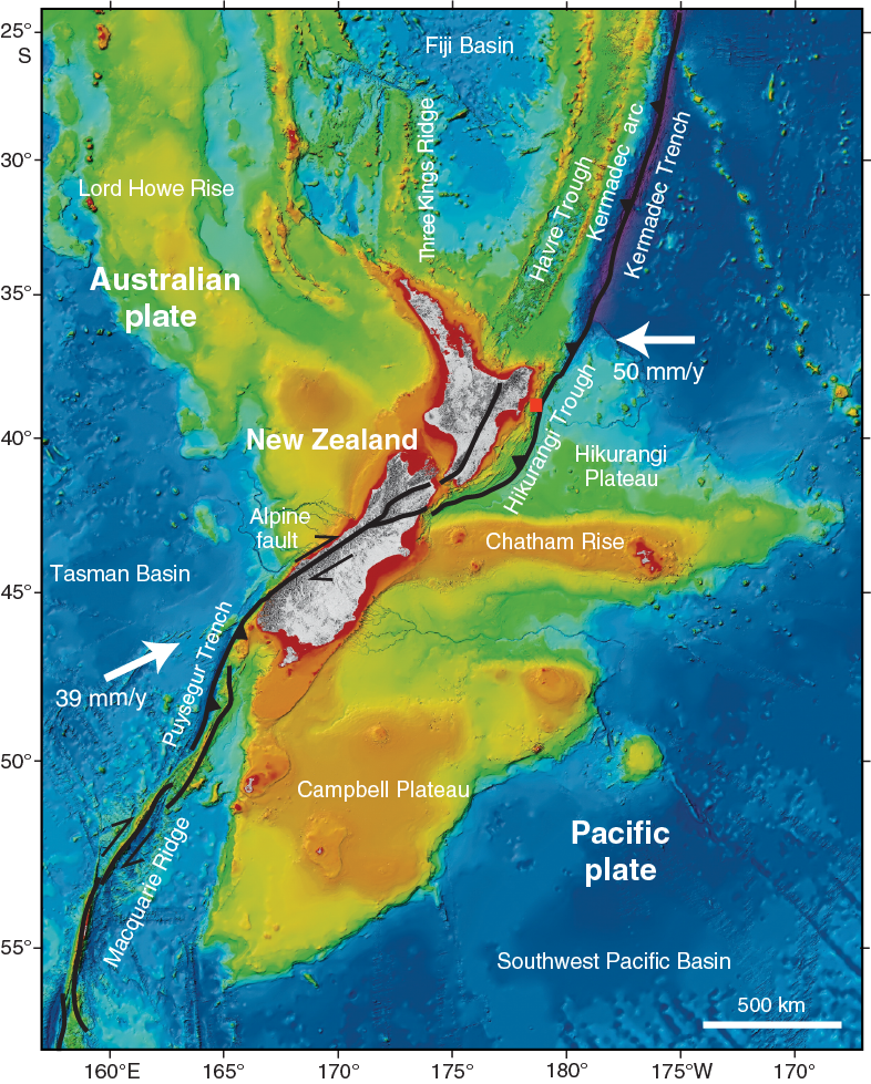
Figure F1. Tectonic setting of study area.
Geologic setting of the Tuaheni Landslide Complex
The TLC is situated on the upper slope of the Hikurangi margin (Figure F2). The outer shelf and upper slope are underlain by Quaternary shelf-edge clinoform sequences (Pedley et al., 2010). These clinoforms consist of wedge-shaped sedimentary packages that are characteristic of sea level cycle–controlled progradational deposits (e.g., Posamentier and Vail, 1988; Van Wagoner et al., 1988). The clinoform sequences are fine grained at the surface (Alexander et al., 2010) but are likely to contain a significant sand fraction at a depth similar to sequences identified in the vicinity of the TLC (Barnes et al., 1991). Late Mesozoic and Cenozoic rocks beneath the Quaternary sections have been exposed following tectonic uplift and erosion (Field et al., 1997; Barnes et al., 2002; Mountjoy and Barnes, 2011).
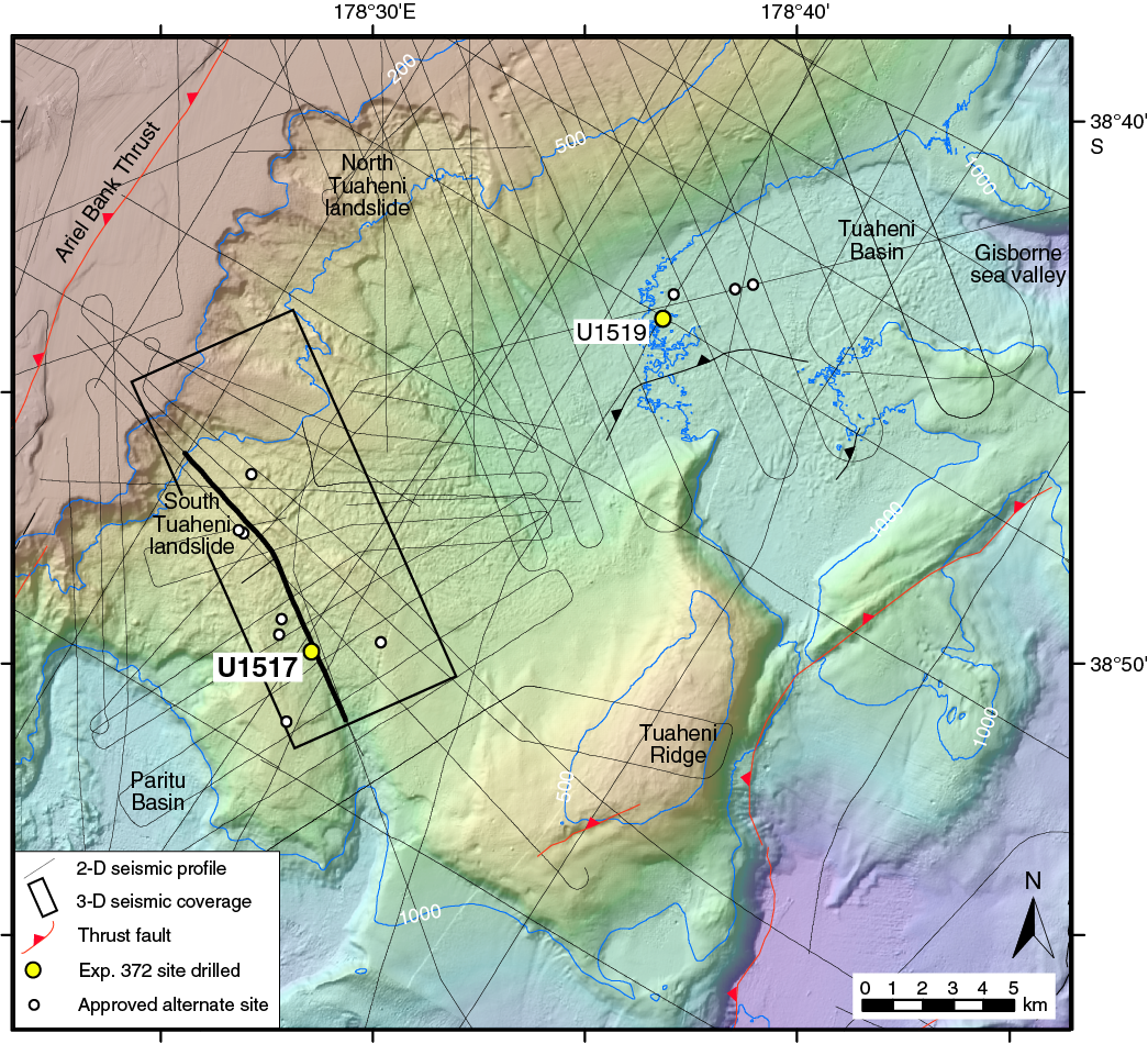
Figure F2. Bathymetry, Site U1517 location, and seismic sections in study area.
Dissociation of gas hydrates has long been proposed as a mechanism responsible for seafloor failure, mainly because of (1) “melting” of a potentially frame-supporting or cementing solid to water and (2) net volume expansion leading to elevated pore pressure caused by the generation of free gas (Kvenvolden, 1993; Mienert et al., 1998). Conversely, a number of laboratory experiments have shown that gas hydrate strengthens sediments (e.g., Winters et al., 2004; Priest et al., 2005). Most studies into the role of gas hydrates in seafloor instability have thus focused on the BGHS, where gas hydrate dissociates. A few recent findings, however, indicate that gas hydrates may directly or indirectly contribute to seafloor weakening. Rock Garden, a ridge on the Hikurangi margin with a flat top flanked by BSRs, appears to be eroded at the predicted FEGHS (Pecher et al., 2005). It has been proposed that gas hydrate indirectly causes seafloor weakening because a reduction of permeability caused by the presence of gas hydrate may lead to the buildup of overpressure and hydrofracturing of the seafloor (Crutchley et al., 2010; Ellis et al., 2010). Furthermore, although earlier laboratory tests suggest that gas hydrate itself, unlike ice, does not exhibit any viscous behavior (Durham et al., 2003), laboratory measurements on sands from the Nankai Trough indicate that gas hydrates may facilitate long-term deformation (Miyazaki et al., 2011). At the TLC, we see evidence that gas buildup and fracturing or viscous processes may occur in nature.
The TLC is thought to have initially formed as a catastrophic submarine slide (the parent slide) followed by ongoing slow deformation of the slide mass. The flanking by elongated strike-slip faults is evidence for slow deformation. The lower edge of the slide mass is unconfined. Morphology of faults in seismic data shows compressional features in the upper part of the slide mass, whereas the lower part shows characteristics of an extensional regime. These observations point toward a conveyor-belt model for sediment movement through the slides, where sediments are being supplied into the upper slide mass, leading to compression, and are being removed at the toe of the TLC, similar to mudslides and rock glaciers on land (Mountjoy et al., 2009).
It was originally suggested that slow deformation in the TLC reflects repeated small-scale seafloor failure associated with localized charging and discharging of pore pressure (Mountjoy et al., 2009) without involvement of gas hydrates. This process would lead to successions of small-scale compressional and extensional features.
We have, however, observed a general switch from compressional to extensional regimes at ~600 m water depth with compression above it and extension, indicating creeping, beneath it (Figure F3). This water depth coincides with the predicted FEGHS. We therefore hypothesized that gas hydrates may cause creeping in the TLC (Mountjoy et al., 2014b). The three proposed mechanisms behind creeping include sliding at the BGHS following gas hydrate dissociation, repeated “breaching” of a permeability boundary at the BGHS that leads to transmission of pressure pulses beneath the creeping part of the slides (“hydrate pressure valve”), and viscous behavior of gas hydrate–bearing sediments (“hydrate glacier”) (Mountjoy et al., 2014b) (Figure F4).
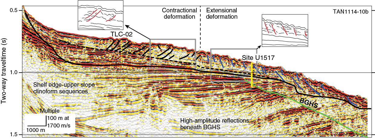
Figure F3. 2-D Seismic Section TAN1114-10b across the TLC.
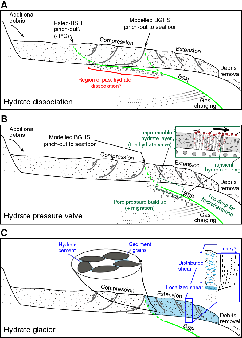
Figure F4. Hypotheses for gas hydrate–related creeping.
Seismic studies/site survey data
The key multichannel seismic data set available in support of the TLC drilling program was a P‐Cable 3-D seismic reflection survey collected during Survey TAN1404 (Mountjoy et al., 2014a). Interpretation of these data confirmed that the transition from a compressional to extensional (creeping) regime generally coincides with the predicted FEGHS. The 3-D seismic cube provided detailed images of the architecture of the TLC (Gross et al., 2018). The following horizons were interpreted beneath the site (Figure F5):
- A possible décollement for creeping at 0.043 s two-way traveltime (TWT) beneath the seafloor (37 meters below seafloor [mbsf] for subseafloor interval velocity of 1700 m/s),
- The base of the debris mass at 0.069 s TWT (59 mbsf), and
- The BGHS at 0.190 s TWT (162 mbsf). The BGHS is mostly defined by the termination of high-amplitude reflections, although BSRs appear in patches along the level of the BGHS.
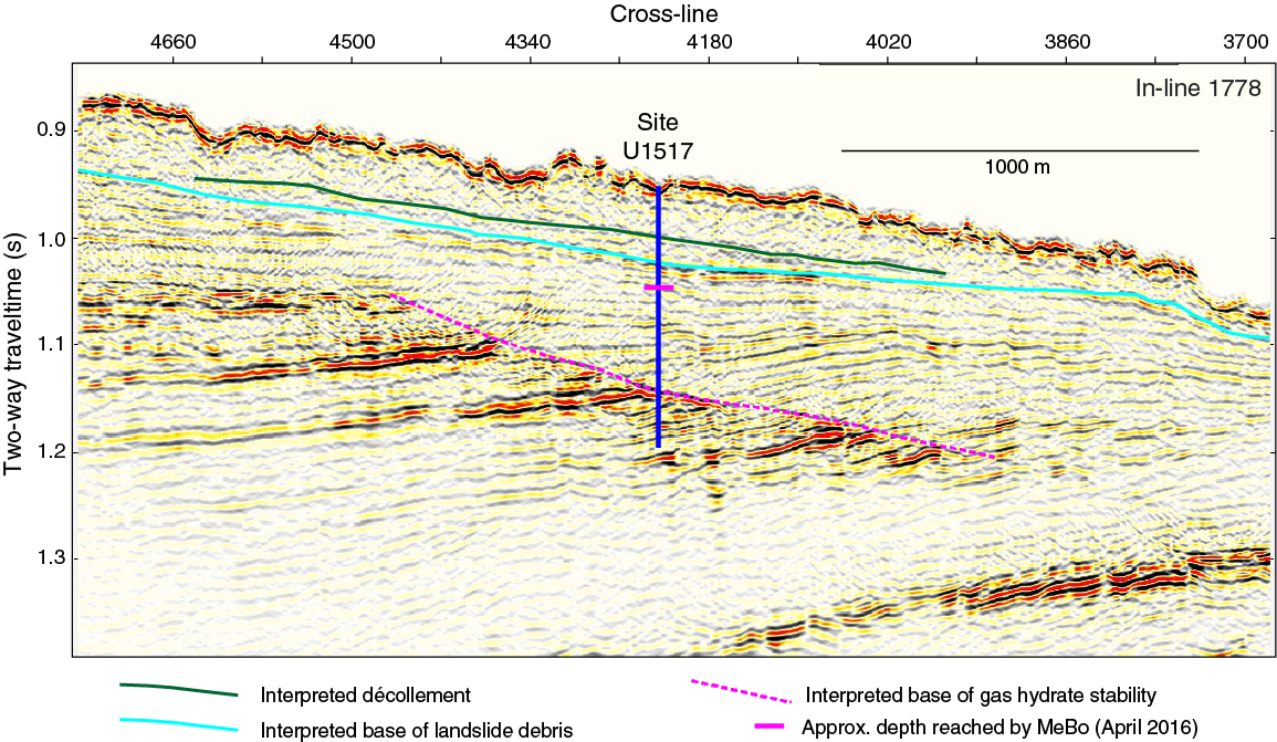
Figure F5. In-line Seismic Section 1778 across Site U1517.
These data were augmented by deep penetration, high-fold seismic sections (Survey 05CM; up to 12 km streamer), low-fold (up to 48 channel) data collected by New Zealand research institutes during two surveys in 2011 (TAN1114) (Barnes and TAN 1114 Scientific Party, 2011) and 2012 (TAN1213), and low-fold high-resolution 2-D multichannel data acquired using the P‐Cable seismic streamers in a 2-D configuration during Survey TAN1404 (Mountjoy et al., 2014a). A long-offset seismic profile, which should provide improved velocity information across Site U1517 (proposed Site TLC-04B), was collected by the R/V Marcus G. Langseth (Cruise MGL 1708) as part of the Seismogenesis at Hikurangi Integrated Research Experiment (SHIRE) project shortly before Expedition 372.
Previous drilling of the Tuaheni Landslide Complex
Two sites were drilled in April–May 2016 in the TLC to ~80 mbsf during the R/V Sonne Voyage SO-247 using the Meeresboden-Bohrgerät 200 (MeBo) robotic drilling system (Site GeoB20831 at Site U1517 and Site GeoB20803 near proposed Site TLC-01D) (Huhn, 2016).
Site U1517 (Figure F5) was drilled to ~80 mbsf with the MeBo system (Site GeoB20831) (Huhn, 2016), encountering deformed clayey silt in the upper 28 m with good core recovery. Between 28 and 60 mbsf, recovery was poor and yielded very fine sandy coarse silt in sections as long as 1.5 m (per 3.5 m stroke length). The cores were highly disturbed by the drilling process and mixed with seawater. From 60 to 78.8 mbsf, stiff clayey silt was sampled from the bedded sedimentary sequence underlying the landslide complex, with good core recovery. The second MeBo site in the TLC (Site GeoB20803) was drilled ~100 m from our proposed alternate Site TLC-01D and yielded similar lithologies, with poor recovery in the upper part of the hole.
MeBo drilling was not successful at recovering material across the interpreted décollement at ~40 mbsf in the seismic data. However, lithologies in the upper and lower parts of the MeBo cores were different, suggestive of a lithologic change across this interpreted décollement. Poor core recovery and extensive seawater contamination precluded pore water analysis for chlorinity as a gas hydrate proxy. MeBo drilling allowed borehole data to be tied to seismic reflections from the intact sequences below landslide debris.
Objectives
Tuaheni Landslide Complex: hypotheses and scientific objectives
We planned to test the following hypotheses that may link gas hydrates to creeping:
- Hypothesis 1: overpressure may lead to slow sliding at the BGHS, in a modification of conventional models linking gas hydrates to seafloor instability (Phrampus and Hornbach, 2012; Figure F4A).
- Hypothesis 2: overpressure at the BGHS causes hydrofracturing, facilitating transmission of overpressure into the gas hydrate zone and sediment weakening, similar to mechanisms proposed for seafloor erosion on Rock Garden south of the TLC (Pecher et al., 2005; Crutchley et al., 2010) (hydrate pressure valve; Figure F4B).
- Hypothesis 3: interstitial gas hydrates in sediments within the TLC slide mass may cause creeping deformation, perhaps because of ice-like viscous behavior of hydrates (hydrate glacier; Figure F4C).
Antitheses (i.e., mechanisms that do not involve gas hydrates) include the following:
- Antithesis 1: creeping in the TLC could be caused by repeated small-scale failure associated with buildup and release of overpressure, the originally proposed mechanism behind creeping (Mountjoy et al., 2009).
- Antithesis 2: earthquake-related liquefaction of coarse silt beds, as detected during recent MeBo drilling, facilitates downslope movement.
Our program was designed to distinguish between the proposed hypotheses based on their following key manifestations:
- Hypothesis 1 (sliding at the BGHS): the key process controlling creeping would be elevated pressure at the BGHS. Temperature profiles will be important to reconstruct past pressure-temperature disturbances that may be causing ongoing gas hydrate dissociation and resulting overpressure.
- Hypothesis 2 (hydrate pressure valve): overpressure is present at the BGHS and transmitted into the gas hydrate stability zone. The presence of a fracture network above the BGHS allows transmission of overpressure to the décollement, which facilitates creeping. No such fracture networks would be expected in the compressional part of the TLC.
- Hypothesis 3 (hydrate glacier): gas hydrate saturation would be expected to change across the décollement. Compressional and extensional parts of the slides would not show any significant differences in terms of pore pressure or fractures.
The antitheses would not predict any anomalies linked to gas hydrate saturation, in particular no pressure disruption at the BGHS or fracture networks related to gas hydrates. The two proposed mechanisms would otherwise have different signatures:
- Antithesis 1 (repeated small-scale seafloor failure): elevated pore pressure would be expected in the compressional regime (pressure charging) compared to the extensional zone (discharged).
- Antithesis 2 (liquefaction of coarse silt beds): cores might reveal localized shearing and liquefaction within the shear zone.
We planned to obtain the necessary data for distinguishing between our proposed creeping mechanisms by achieving the following objectives through drilling the TLC.
- Obtain lithologic information within the creeping slides, in particular across the proposed décollement of creeping.
Coring was planned to obtain information on the lithology within the creeping, extensional part of the TLC and the underlying sediments. Recovering cores across the proposed décollement for creeping, from which MeBo drilling did not obtain any cores, was a high priority. Lithologic information using the R/V JOIDES Resolution’s advanced piston corer (APC) and half-length APC (HLAPC) systems will be extrapolated based on seismic data.
The microscopic distribution of gas hydrate in sediments and its interaction with the sediment frame may be highly dependent on porosity distribution and sediment composition (e.g., the presence of clay minerals). We planned to test whether and how creeping may be linked to viscous behavior of the hydrate-sediment mix by conducting laboratory measurements on material recovered from the TLC. Gas hydrates may be formed in intact or reconstituted sediments from APC or HLAPC cores.
Gas hydrate saturation with depth is a key parameter to address all three proposed hydrate-related creep mechanisms. We planned to constrain profiles of gas hydrate saturation with depth based on logging-while-drilling (LWD) and pore water chlorinity data from APC and HLAPC cores. Degassing of pressure cores was planned for additional calibration of gas hydrate saturation and for determination of the hydrate-forming gas composition. The gas composition is important for hydrate stability calculations and improved understanding of the general gas and gas hydrate system at the TLC. Furthermore, pore water profiles provide information on fluid sources and chemical disequilibria.
Both models of the hydrate pressure valve and sliding at the BGHS involve pore pressure anomalies. In addition, the antithesis of repeated small-scale sliding at the BGHS without gas hydrate involvement is predicted to have a characteristic pressure signature. Pore pressure profiles are particularly important in the creeping extensional regime, where we planned a program using the temperature dual-pressure probe (T2P) to calibrate pore pressure. Emphasis was on pore pressure changes across the proposed décollement and the BGHS. Temperature profiles are needed to constrain gas hydrate stability. Furthermore, changes in paleo–bottom water temperatures are a possible cause for gas hydrate dissociation leading to overpressure and sliding at the BGHS. Such bottom water changes would be reflected in anomalous temperature profiles with depth. We planned to measure subseafloor temperatures with the third generation advanced piston corer temperature tool (APCT-3) and the sediment temperature pressure tool (SETP).
The hydrate pressure valve model predicts transmission of pore pressure through fractures from hydraulic or pneumatic fracturing. We planned to constrain sediment fracturing as a function of depth at all three sites based on LWD data, particularly the resistivity images.
Further quantitative analysis of the 3-D seismic data will aim at constraining potential lateral pressure variation along the décollement and deeper layers. Results from LWD velocity logs, tied with pressure profiles, will allow calibration of the seismic data. Furthermore, the LWD data may also provide shear wave calibration for long-offset seismic lines (MacMahon, 2016) and ocean-bottom seismometer site survey data (Wild, 2016) with the aim of extracting subsurface S-wave velocities using amplitude versus offset and P-to-S converted waves.
Principal results
Site U1517
Site U1517 is located in the extensional, creeping part of the TLC at ~720 m water depth (Figures F2, F3). The primary drilling objectives were to use LWD and sample through the landslide mass and the gas hydrate stability zone to understand the mechanisms behind creeping.
The site was selected based on 3-D site survey data and was previously drilled to 80 mbsf with the MeBo system (Site GeoB20831) during Sonne Voyage SO-247. See Objectives for site objectives.
Hole U1517A was drilled to 205 mbsf with LWD starting on 16 December 2017. The vessel was offset by 20 m for Hole U1517B, which was abandoned because of uncertainties in the position of the mudline. Hole U1517C was drilled at the same location as Hole U1517B for APC/HLAPC coring and reached 188.5 mbsf. The vessel then left Site U1517 for completion of the remaining LWD program for the Hikurangi margin before returning to the site on 31 December to drill Hole U1517D for T2P/SETP deployments (Table T1).
Core lithology and structure
The lithostratigraphy in Hole U1517C is characterized as clayey silt with sandy intervals (Figure F6). We defined five lithostratigraphic units (I–V) based on visual description of core material, smear slide analysis, and red-green-blue (RGB) color and magnetic susceptibility logs. Smear slide analysis shows that Units I–IV have distinct characteristics with an overall decrease in grain size downcore from Unit I to Unit IV, whereas Unit V includes a broad distribution of grain sizes. A variety of drilling-related core disturbance occurred that made robust interpretation of sedimentary structure challenging. Sedimentary structures including sharp upper contacts and irregular basal contacts in graded beds suggest that significant postdepositional modification of the beds has taken place. Overall, we interpret this stratigraphic succession as including bedded turbidite sequences, mass transport deposits (MTDs), and background hemipelagic sedimentation. The upper ~67 m is within the TLC and appears to be primarily an intact block that likely mobilized from the upper slope sedimentary sequences.
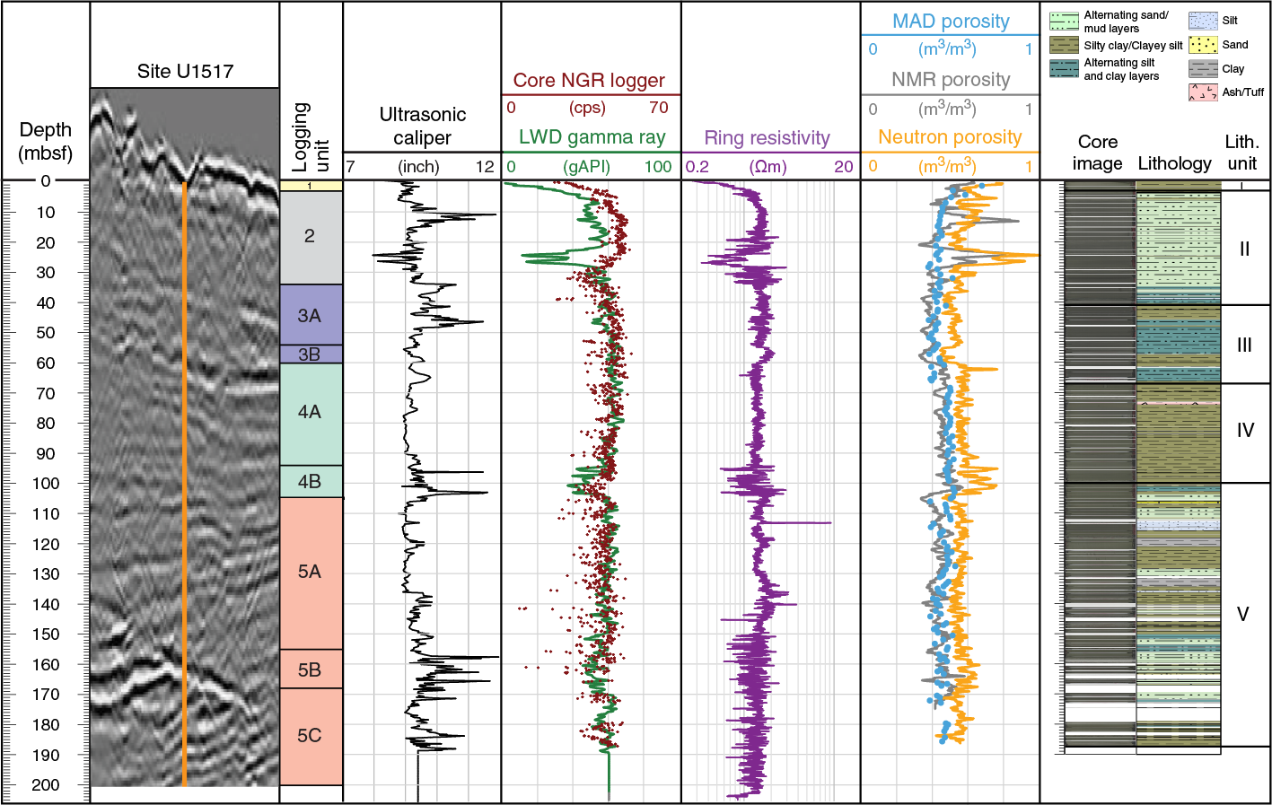
Figure F6. In-line Seismic Section 1778 and Site U1517 LWD and cores.
Biostratigraphy
Calcareous nannofossils and planktonic foraminifers were examined from core catcher samples and additional split-core samples to develop a shipboard biostratigraphic framework for Site U1517. Benthic foraminifers were also examined to provide data on paleowater depths and downslope reworking.
A Holocene to middle Pleistocene sedimentary sequence was recovered at Site U1517. The base of the Holocene is placed at 3.34–4.92 mbsf, at the level of a lithologic change from relatively soft (featureless) bioturbated silty claystone to a compacted thin-bedded silty claystone sequence and at an abrupt shift in physical properties. The underlying section is Middle to Late Pleistocene in age (11–530 ka). From biostratigraphic dating, the average sedimentation rate for Site U1517 is estimated to be ~0.8 m/ky.
Paleomagnetism
We measured paleomagnetic inclination, declination, and intensity records of natural remanent magnetization (NRM). Site U1517 sections were demagnetized to a peak field of 20 or 30 mT. Measured NRM inclination shows a pervasive overprint along core that manifests in steeply dipping and downward facing inclinations and most likely represents a viscous remanent magnetization acquired during the drilling process. This overprint was successfully removed at the 10 or 20 mT demagnetization level.
In Lithostratigraphic Units I–IV, core recovery was high and all sections were largely undisturbed so that depositional remanences were adequately preserved. However, a slight deformation along the core liners (or “bed drag”) often resulted in a slight concave curvature of the bedding that may have affected the recorded remanence directions.
NRM intensity prior to demagnetization ranged from 4 × 10⁻³ to 0.1 A/m. Peak values coincided with sand-bearing units encountered in Lithostratigraphic Units I and V and are coherent with the higher magnetic susceptibility values measured in these intervals.
The entire sequence recovered at Site U1517 yields NRM directions with upward-facing (negative) inclinations following demagnetization to 20 mT. Preliminary biostratigraphic datums suggest that the material at this site is no older than 0.53 Ma, and we thus infer that the depositional remanences measured were acquired during the Brunhes Normal Chron (C1n) (Gradstein et al., 2012).
Geochemistry
We collected 75 whole-round samples for characterization of the pore water in Hole U1517C. Samples were collected on the catwalk at a frequency of four samples per core in the upper 15.2 m and two samples per core from 15.2 to 112.4 mbsf. Below this depth, sample selection was guided by cold anomalies observed in infrared camera images that suggested the potential for gas hydrate occurrence. Additional samples were taken away from the cold anomalies to establish the in situ background chloride concentrations. Dissolved chloride measurements indicate the presence of discrete gas hydrate occurrences between ~135 and 165 mbsf, with hydrate saturation (Sh) values ranging from 2% to 68%. This distribution is consistent with inferences on gas hydrate saturation based on resistivity data obtained by LWD. When it was possible to isolate thin, dark, coarse silt layers from the background fine clay matrix, we analyzed each lithology separately. In these separated samples, the thin coarse layers within the whole-round host gas hydrate at saturations ranging from 5% to 50%, whereas gas hydrate in the fine clay immediately in contact with the gas hydrate–bearing, coarse-grained layers ranged from nondetectable to 2%. This illustrates the preferential occurrence of gas hydrate in the coarse-grained material.
Pore fluid composition reflects the combined effects of microbially mediated organic matter degradation coupled to carbonate and silica diagenetic changes. The sulfate–methane transition (SMT) is well defined at 17 mbsf by depletion of dissolved sulfate and a marked increase in methane concentration in headspace samples. Alkalinity, calcium, and magnesium show distributions that are typical for reactions occurring at the SMT. Pore water profiles in the methanogenic zone suggest a combination of reactions that may include silicate weathering and formation of authigenic minerals that modify the iron, manganese, calcium, and potassium pore water profiles.
Below the SMT, methane concentrations rapidly increase to as much as 1%, indicating ongoing methanogenesis. The measured methane concentrations below the SMT are close to or above pore water saturation at ambient conditions. These values are qualitative estimates only because they reflect the amount of gas remaining in the sediment after core recovery and handling rather than the original values. Ethane was not detected in gas samples from the headspace nor from voids shallower than 146 mbsf, but it was repeatedly measured at very low concentrations of 1–2 parts per million by volume (ppmv) between 146 and 166 mbsf, a depth range that coincides with the inferred presence of gas hydrate. No other higher-order hydrocarbons were detected.
Solid-phase analyses yielded CaCO3 contents ranging from 4.63 to 8.99 wt% (mean = 6.52 ± 1.13 wt%). Total organic carbon contents are generally <1 wt%, with slightly higher concentrations in Lithostratigraphic Unit IV (mean = 0.71 ± 0.16 wt% organic carbon within this unit) and a few measurements that reached 1.68 wt% in Unit V. The C/N ratios ranged from 3.78 to 31.34 (mean = 9.46 ± 3.52), with variations that suggest higher heterogeneity of the organic matter in Units II and V.
Based on infrared anomalies, 13 whole rounds that likely contained gas hydrates were removed from the core at the catwalk. These samples were immediately stored in liquid nitrogen for shipment to the GeoForschungsZentrum Potsdam (Germany), Qingdao Institute of Marine Geology (China), and British Geological Survey, where shore-based gas hydrate studies will be conducted.
Physical properties
Physical properties were characterized through a set of measurements on whole cores, split cores, and discrete samples. The magnetic susceptibility profile generally corresponds to the lithostratigraphic units, with sequences of sand and mud showing more variable magnetic susceptibility than laminated clay and silt or massive silty clay. Moisture and density (MAD) measurements on discrete samples from cores indicate relatively low porosity (~0.44) starting a few meters below the seafloor (Figure F6). A porosity shift occurs at 66 mbsf, with values increasing to ~0.48. P-wave velocity and strength measurements on cores were compromised or prevented by expansion caused by gas disturbance deeper than 20 mbsf. Thermal conductivity measurements yield values averaging 1.2 W/(m·K) in the cored section. Fluctuations in thermal conductivity are small and appear inversely related to porosity, which is expected based on the higher thermal conductivity of solids.
Downhole measurements
The APCT-3 was deployed seven times in Hole U1517C. Four successful deployments between 81 and 132 mbsf define a linear temperature-depth profile with a gradient of 39.8°C/km. This gradient, combined with the average thermal conductivity measured on cores, yields an estimate of vertical conductive heat flow of 49 mW/m2.
Four attempts were made to measure in situ formation pressure and temperature in Hole U1517D. The T2P was deployed at 80 and 120 mbsf. The first deployment returned a good formation pressure measurement. The second deployment may have collected good data, but it could not be retrieved because the electronics flooded. The SETP was deployed at 130 and 168.7 mbsf. Tool deployment and recovery went smoothly; however, the data file of the first measurement was erased from the memory card and the data file of the second measurement was corrupted. Post-expedition efforts to recover these data were unsuccessful.
Logging while drilling
LWD tools collected data in Hole U1517A to the target depth of 205 mbsf (Table T1). Five LWD tools were deployed on the bottom-hole assembly (BHA): geoVISION, SonicScope, NeoScope, TeleScope, and proVISION. These provided data in real time and recorded modes through the TLC, across and below the décollement, and through the BSR. Based on the LWD measurements, five main logging units were identified that closely correspond to the lithostratigraphic units defined for Hole U1517C (Figure F6). Several significant features were interpreted from the logs, such as the compacted base of the debris flow from 54 to 60 mbsf and natural gas hydrate occurring in 10–30 cm thick turbidite sands from 110 to 150 mbsf. Both conductive and resistive fractures were also identified throughout the hole, with a higher fracture density within the landslide complex. Gas hydrate occurrences were predicted based on resistivity anomalies between 113.0 and 145.5 mbsf.
Core-log integration
By integrating LWD data from Hole U1517A and core-derived information from Hole U1517C, we compared LWD data with physical property measurements on core (natural gamma radiation [NGR], sonic P-wave velocity, porosity, and bulk density). Whole-round NGR measurements are in agreement with those taken through LWD. Additionally, core sample–derived MAD porosities agree well with measured LWD nuclear magnetic resonance (NMR) porosities, but MAD measurements are consistently lower than the LWD neutron porosity measurements (Figure F6). Furthermore, the depths at which significant changes in measurement responses occur appear slightly mismatched: in the shallow section above 70 mbsf, excursions from baseline values appear approximately 5 m lower in core data than LWD data. This observation is consistent across both the NGR and porosity measurements. This mismatch is less pronounced deeper in the holes.
Hydrate saturation was estimated using LWD-based methods and core geochemistry analysis. These techniques agree in their assessment of the most probable areas of hydrate occurrence, although they disagree in their predictions of hydrate saturation magnitude, which is likely due to differences in sampling resolution and formation heterogeneity.
Log-seismic integration
LWD logs were tied to the In-line 1778 profile of the Tuaheni 3-D seismic volume through a set of synthetic seismograms (Figure F6). Two sets of synthetics were constructed. One set edited the LWD density and velocity logs to create acoustic impedance logs that were convolved with a wavelet derived from the seafloor reflection in the seismic data. The other set used a log-lithologic model of the main lithostratigraphic units and physical properties. Washouts caused by silty/sandy lithologies led to relatively poor quality of the density and velocity logs in these intervals. Therefore, the synthetic seismograms did not match the seismic reflection data well. Nevertheless, we were able to tie the main lithostratigraphic and logging units to the seismic units.
Preliminary scientific assessment
Tuaheni Landslide Complex
The primary drilling goal for the TLC was to understand the mechanisms behind the slow deformation of the landslides and their proposed links to gas hydrates by logging and sampling through the landslide mass and the gas hydrate stability zone.
Operationally, we originally planned to conduct LWD surveys at three sites: the main Site U1517 in the extensional, creeping part of the TLC, a site in the compressional part of the TLC above the BGHS pinch-out (planned primary Site TLC-02C), and a reference site outside the slide mass (planned primary Site TLC-03B). We planned to core Site U1517 with the APC/HLAPC system and deploy the T2P/SETP to measure pore pressure and temperature and the pressure core sampler (PCS) to collect sediment cores under pressure for calibration of gas hydrate saturation and for gas hydrate composition. This plan would allow a comprehensive study of the creeping part of the TLC and comparison with both its compressional part and gas hydrates in the vicinity but outside the slide mass. Because of significant downtime because of poor weather and a delayed departure from Fremantle, Australia, we focused all our operations on the main site (U1517), conducting LWD, coring, and a reduced number of T2P/SETP stations, skipping the other two sites. This compromise aimed to minimize the impact of reduced operational time on addressing our scientific goals.
Meeting the objectives of the expedition: Tuaheni Landslide Complex
We consider the TLC program overall successful in terms of allowing us to test our hypotheses and antitheses despite the significant downtime we experienced. Importantly, we were able to complete almost the entire planned program at the main site (U1517). We were not, however, able to log either the site in the compressional part of the slides (proposed Site TLC-02C) or the reference site outside the slide mass (proposed Site TLC-03B). Results from gas hydrate occurrences in the deeper preslide mass interval at Site U1517, combined with the detection of gas hydrates at Site U1519 (Barnes et al., 2019), should allow us to interpret results from Site U1517 without a reference site. Extension of results from Site U1517 based on recently acquired long-offset 2-D seismic data should also alleviate the lack of LWD in the compressional part of the slide. We were fortunate to still be able to deploy the T2P and SETP in a very limited time window at the end of the expedition. One of the two T2P deployments successfully provided a reading of formation pressure. Unfortunately, SETP data could not be recovered. We could not deploy the PCS because of time constraints. Pressure coring would have improved constraints on gas hydrate saturation and composition. We are confident that we were able to get accurate and continuous profiles of gas hydrate saturation because of the high quality of the LWD data. The recovered gas hydrate samples should provide information on gas hydrate composition.
We have largely achieved the following scientific objectives:
- Obtain lithologic information within the creeping slides, in particular across the proposed décollement of creeping. We had >90% core recovery, with the only major gaps occurring below the BGHS, probably due to gas expansion.
- Collect samples for shore-based laboratory studies. This objective relates to gas hydrate studies. In addition to the gas hydrate–bearing samples, we collected a number of whole rounds and sediment samples for laboratory studies involving artificial gas hydrate formation followed by geomechanical measurements.
- Constrain in situ gas hydrate saturation and composition. Because of the generally high quality of logs and good core recovery, including retrieval of gas hydrate samples, we are confident this objective has been achieved for Site U1517.
- Obtain pore pressure and temperature profiles. We were able to measure the temperature gradient above the BGHS. We successfully measured formation pressure at a critical depth near the base of the landslide debris. We were not able to retrieve data from a second T2P deployment nor any information from the SETP. Nevertheless, the successful measurements significantly enhance our constraints on pressure and temperature profiles.
- Search for evidence of fracturing. Resistivity images from LWD will allow us to detect fracturing at Site U1517. Although we will not be able to compare fracture patterns with those in the compressional region of the slides, we may still be able to gain some information on changes in any fracture patterns from the seismic data and core computed tomography (CT) imagery.
- Calibrate seismic data. The logs should provide full calibration of the short-streamer 3-D seismic site survey at Site U1517. Canceling two additional holes in the 3-D cube will increase uncertainties in inversion approaches away from Site U1517, but this effect is partly alleviated by the acquisition of a long-streamer seismic line across Site U1517 by Marcus G. Langseth in November and December 2017, which will enhance constraints away from the borehole.
Furthermore, by industry standards, the LWD data were collected in relatively shallow sediments. Post-expedition research subsequently includes development of LWD validation, characterization, and methodology in these settings.
In terms of studying the processes behind active deformation in the TLC, LWD- and laboratory-based physical properties indicate consistent variation between the landslide debris mass and underlying sediment. Disequilibrium profiles from geochemical results through the TLC reflect temporal elements of the depositional structure of the system. Core lithologies are dominated by graded fine sandy beds and clayey silts, including many turbidites. These results, combined with core-log and seismic integration that provides petrophysical properties within the slide mass and surrounding lithologies, provide an exceptional framework for analyzing active landslide processes.
In a broader sense, the nearly full recovery of cores through the landslide and the gas hydrate zone provides us with a good record of sedimentology, lithology, physical properties, and geochemistry. The LWD data are generally of high quality, providing important structural and geophysical information, as well as calibration for the various seismic data sets covering the TLC. We are thus confident that post-expedition analyses will allow us to unravel the processes leading to “creeping” of the TLC—the primary aim for Site U1517.
References
Alexander, C.R., Walsh, J.P., and Orpin, A.R., 2010. Modern sediment dispersal and accumulation on the outer Poverty continental margin. Marine Geology, 270(1–4):213–226. https://doi.org/10.1016/j.margeo.2009.10.015
Barker, D.H.N., Henrys, S., Caratori Tontini, F., Barnes, P. M., Bassett, D., Todd, E., and Wallace, L., 2018. Geophysical constraints on the relationship between seamount subduction, slow slip and tremor at the north Hikurangi subduction zone, New Zealand. Geophysical Research Letters, 45. https://doi.org/10.1029/2018GL080259
Barker, D.H.N., Sutherland, R., Henrys, S., and Bannister, S., 2009. Geometry of the Hikurangi subduction thrust and upper plate, North Island, New Zealand. Geochemistry, Geophysics, Geosystems, 10(2):Q02007. https://doi.org/10.1029/2008GC002153
Barnes, P., and TAN 1114 Scientific Party, 2011. NIWA Voyage Report TAN1114: Auckland, New Zealand (National Institute of Water and Atmospheric Research). https://www.niwa.co.nz/sites/niwa.co.nz/files/os2020_northern_hikurangi_margin_geohazards.pdf
Barnes, P.M., Cheung, K.C., Smits, A.P., Almagor, G., Read, S.A.L., Barker, P.R., and Froggatt, P., 1991. Geotechnical analysis of the Kidnappers slide, upper continental slope, New Zealand. Marine Geotechnology, 10(1–2):159–188. https://doi.org/10.1080/10641199109379888
Barnes, P.M., Nicol, A., and Harrison, T., 2002. Late Cenozoic evolution and earthquake potential of an active listric thrust complex above the Hikurangi subduction zone, New Zealand. Geological Society of America Bulletin, 114(11):1379–1405. https://doi.org/10.1130/0016-7606(2002)114<1379:LCEAEP>2.0.CO;2
Barnes, P.M., Wallace, L.M., Saffer, D.M., Pecher, I.A., Petronotis, K.E., LeVay, L.J., Bell, R.E., Crundwell, M.P., Engelmann de Oliveira, C.H., Fagereng, A., Fulton, P.M., Greve, A., Harris, R.N., Hashimoto, Y., Hüpers, A., Ikari, M.J., Ito, Y., Kitajima, H., Kutterolf, S., Lee, H., Li, X., Luo, M., Malie, P.R., Meneghini, F., Morgan, J.K., Noda, A., Rabinowitz, H.S., Savage, H.M., Shepherd, C.L., Shreedharan, S., Solomon, E.A., Underwood, M.B., Wang, M., Woodhouse, A.D., Bourlange, S.M., Brunet, M.M.Y., Cardona, S., Clennell, M.B., Cook, A.E., Dugan, B., Elger, J., Gamboa, D., Georgiopoulou, A., Han, S., Heeschen, K.U., Hu, G., Kim, G.Y., Koge, H., Machado, K.S., McNamara, D.D., Moore, G.F., Mountjoy, J.J., Nole, M.A., Owari, S., Paganoni, M., Rose, P.S., Screaton, E.J., Shankar, U., Torres, M.E., Wang, X., and Wu, H.-Y., 2019. Site U1519. In Wallace, L.M., Saffer, D.M., Barnes, P.M., Pecher, I.A., Petronotis, K.E., LeVay, L.J., and the Expedition 372/375 Scientists, Hikurangi Subduction Margin Coring, Logging, and Observatories. Proceedings of the International Ocean Discovery Program, 372B/375: College Station, TX (International Ocean Discovery Program). https://doi.org/10.14379/iodp.proc.372B375.104.2019
Baum, R.L., Savage, W.Z., and Wasowski, J., 2003. Mechanics of earthflows. In Picarelli, L. (Ed.), Proceedings of the International Workshop on Occurrence and Mechanisms of Flow-Like Landslides in Natural Slopes and Earthfills: Bologna, Italy (Associazione Geotechnica Italiana), 185–190.
Bell, R., Sutherland, R., Barker, D.H.N., Henrys, S., Bannister, S., Wallace, L., and Beavan, J., 2010. Seismic reflection character of the Hikurangi subduction interface, New Zealand, in the region of repeated Gisborne slow slip events. Geophysical Journal International, 180(1):34–48. https//doi.org/10.1111/j.1365-246X.2009.04401.x
Chiswell, S., 2005. Mean and variability in the Wairarapa and Hikurangi Eddies, New Zealand. New Zealand Journal of Marine and Freshwater Research, 39(1):121–134. https://doi.org/10.1080/00288330.2005.9517295
Collot, J.-Y., Lewis, K., Lamarache, G., and Lallemand, S., 2001. The giant Ruatoria debris avalanche on the northern Hikurangi margin, New Zealand; result of oblique seamount subduction. Journal of Geophysical Research: Solid Earth, 106(B9):19271–19297. https://doi.org/10.1029/2001JB900004
Crutchley, G.J., Geiger, S., Pecher, I.A., Gorman, A.R., Zhu, H., and Henrys, S.A., 2010. The potential influence of shallow gas and gas hydrates on sea floor erosion of Rock Garden, an uplifted ridge offshore of New Zealand. Geo-Marine Letters, 30(3–4):283–303. https://doi.org/10.1007/s00367-010-0186-y
Durham, W.B., Kirby, S.H., Stern, L.A., and Zhang, W., 2003. The strength and rheology of methane clathrate hydrate. Journal of Geophysical Research: Solid Earth, 108(B4):2182. https://doi.org/10.1029/2002JB001872
Ellis, S., Fagereng, Å., Barker, D., Henrys, S., Saffer, D., Wallace, L., Williams, C., and Harris, R., 2015. Fluid budgets along the northern Hikurangi subduction margin, New Zealand: the effect of a subducting seamount on fluid pressure. Geophysical Journal International, 202(1):277–297. https://doi.org/10.1093/gji/ggv127
Ellis, S., Pecher, I., Kukowski, N., Xu, W., Henrys, S., and Greinert, J., 2010. Testing proposed mechanisms for seafloor weakening at the top of gas hydrate stability on an uplifted submarine ridge (Rock Garden), New Zealand. Marine Geology, 272(1–4):127–140. https://doi.org/10.1016/j.margeo.2009.10.008
Field, B.D., Uruski, C.I., Bey, A., Browne, G., Crampton, J., Funnell, R., Killops, S., Laird, M., Mazengarb, C., Morgans, H., Rait, G., Smale, D., and Strong, P., 1997. Cretaceous–Cenozoic Geology and Petroleum Systems of the East Coast Region, New Zealand (Volume 19): Lower Hutt, New Zealand (Institute of Geological and Nuclear Sciences).
Gradstein, F.M., Ogg, J.G., Schmitz, M.D., and Ogg, G.M. (Eds.), 2012. The Geological Time Scale 2012: Amsterdam (Elsevier). https://doi.org/10.1016/C2011-1-08249-8
Gross, F., Mountjoy, J.J., Crutchley, G.J., Böttner, C., Koch, S., Bialas, J., Pecher, I., et al., 2018. Free gas distribution and basal shear zone development in a subaqueous landslide—insight from 3D seismic imaging of the Tuaheni Landslide Complex, New Zealand. Earth and Planetary Science Letters, 502:231–243. https://doi.org/10.1016/j.epsl.2018.09.002
Huhn, K., 2016. DSRV Sonne SO247 Cruise Report—SlamZ: slide activity on the Hikurangi margin, New Zealand, Wellington–Auckland, 27 March–27 April 2016. Bundesministerium für Bildung und Forschung. https://www.portal-forschungsschiffe.de/lw_resource/datapool/_items/item_183/fahrtbericht_so247.pdf
Kvenvolden, K.A., 1993. Gas hydrates—geological perspective and global change. Reviews of Geophysics, 31(2):173–187. https://doi.org/10.1029/93RG00268
Lewis, K.B., Collot, J.-Y., and Lallemand, S.E., 1998. The dammed Hikurangi Trough: a channel-fed trench blocked by subducting seamounts and their wake avalanches (New Zealand–France GeodyNZ Project). Basin Research, 10(4):441–468. https://doi.org/10.1046/j.1365-2117.1998.00080.x
MacMahon, J., 2016. High-resolution velocity analysis of seismic data to identify gas hydrates in the Tuaheni Landslide Complex on the Hikurangi margin, New Zealand [M.S. thesis]. University of Auckland, New Zealand. http://hdl.handle.net/2292/28209
Martin, H.E., and Whalley, W.B., 1987. Rock glaciers. Part 1: rock glacier morphology: classification and distribution. Progress in Physical Geography, 11(2):260–282. https://doi.org/10.1177/030913338701100205
Mienert, J., Posewang, J., and Baumann, M., 1998. Gas hydrates along the northeastern Atlantic margin: possible hydrate-bound margin instabilities and possible release of methane. In Henriet, J.-P., and Mienert, J. (Eds.), Gas Hydrates: Relevance to World Margin Stability and Climate Change. Geological Society Special Publication, 137(1):275–291. https://doi.org/10.1144/GSL.SP.1998.137.01.22
Miyazaki, K., Yamaguchi, T., Sakamoto, Y., and Aoki, K., 2011. Time-dependent behaviors of methane-hydrate bearing sediments in triaxial compression test. International Journal of the JCRM, 7(1):43–48. https://doi.org/10.11187/ijjcrm.7.43
Mountjoy, J., Krastel, S., Crutchley, G., Dannonski, A., Graw, M., Koch, S., Micallef, A., Quinn, W., and Woelz, S., 2014a. NIWA Voyage Report TAN1404: SCHLIP-3D: submarine clathrate hydrate landslide imaging project: Auckland, New Zealand (National Institute of Water and Atmospheric Research).
Mountjoy, J.J., and Barnes, P., 2011. Active upper plate thrust faulting in regions of low plate interface coupling, repeated slow slip events, and coastal uplift: example from the Hikurangi margin, New Zealand. Geochemistry, Geophysics, Geosystems, 12(1):Q01005. https://doi.org/10.1029/2010GC003326
Mountjoy, J.J., McKean, J., Barnes, P.M., and Pettinga, J.R., 2009. Terrestrial-style slow-moving earthflow kinematics in a submarine landslide complex. Marine Geology, 267(3–4):114–127. https://doi.org/10.1016/j.margeo.2009.09.007
Mountjoy, J.J., Pecher, I., Henrys, S., Crutchley, G., Barnes, P.M., and Plaza-Faverola, A., 2014b. Shallow methane hydrate system controls ongoing, downslope sediment transport in a low-velocity active submarine landslide complex, Hikurangi Margin, New Zealand. Geochemistry, Geophysics, Geosystems, 15(11):4137–4156. https://doi.org/10.1002/2014GC005379
Mulder, T., and Cochonat, P., 1996. Classification of offshore mass movements. Journal of Sedimentary Research, 66(1):43–57. https://doi.org/10.1306/D42682AC-2B26-11D7-8648000102C1865D
Pecher, I.A., Henrys, S.A., Ellis, S., Chiswell, S.M., and Kukowski, N., 2005. Erosion of the seafloor at the top of the gas hydrate stability zone on the Hikurangi margin, New Zealand. Geophysical Research Letters, 32(24):L24603. https://doi.org/10.1029/2005GL024687
Pecher, I.A., Henrys, S.A., Ellis, S., Crutchley, G., Fohrmann, M., Gorman, A.R., Greinert, J., Chiswell, S.M., TAN0607 Scientific Party, and SO191 Scientific Party, 2008. Erosion of seafloor ridges at the top of the gas hydrate stability zone, Hikurangi margin, New Zealand—new insights from research cruises between 2005 and 2007 [paper presented at the 6th International Conference on Gas Hydrates, Vancouver, Canada, 6–10 July 2008]. https://open.library.ubc.ca/cIRcle/collections/59278/items/1.0041097
Pecher, I.A., Villinger, H., Kaul, N., Crutchley, G.J., Mountjoy, J.J., Huhn, K., Kukowski, N., Henrys, S.A., Rose, P.S., and Coffin, R.B., 2017. A fluid pulse on the Hikurangi Subduction Margin: evidence from a heat flux transect across the upper limit of gas hydrate stability. Geophysical Research Letters, 44(24):12385–12395. https://doi.org/10.1002/2017GL076368
Pedley, K.L., Barnes, P.M., Pettinga, J.R., and Lewis, K.B., 2010. Seafloor structural geomorphic evolution of the accretionary frontal wedge in response to seamount subduction, Poverty Indentation, New Zealand. Marine Geology, 270(1–4):119–138. https://doi.org/10.1016/j.margeo.2009.11.006
Phrampus, B.J., and Hornbach, M.J., 2012. Recent changes to the Gulf Stream causing widespread gas hydrate destabilization. Nature, 490(7421):527–530. https://doi.org/10.1038/nature11528
Posamentier, H.W., and Vail, P.R., 1988. Eustatic controls on clastic deposition II—sequence and systems tract models. In Wilgus, C.K., Hastings, B.S., Posamentier, H., Van Wagoner, J., Ross, C.A., and Kendall, C.G.St.C. (Eds.), Sea-Level Changes: An Integrated Approach. Special Publication - SEPM (Society of Sedimentary Geologists), 42:125–154. https://doi.org/10.2110/pec.88.01.0125
Priest, J.A., Best, A.I., and Clayton, C.R.I., 2005. A laboratory investigation into the seismic velocities of methane gas hydrate-bearing sand. Journal of Geophysical Research: Solid Earth, 110(B4):B04102. https://doi.org/10.1029/2004JB003259
Saffer, D.M., Wallace, L.M., Barnes, P.M., Pecher, I.A., Petronotis, K.E., LeVay, L.J., Bell, R.E., Crundwell, M.P., Engelmann de Oliveira, C.H., Fagereng, A., Fulton, P.M., Greve, A., Harris, R.N., Hashimoto, Y., Hüpers, A., Ikari, M.J., Ito, Y., Kitajima, H., Kutterolf, S., Lee, H., Li, X., Luo, M., Malie, P.R., Meneghini, F., Morgan, J.K., Noda, A., Rabinowitz, H.S., Savage, H.M., Shepherd, C.L., Shreedharan, S., Solomon, E.A., Underwood, M.B., Wang, M., Woodhouse, A.D., Bourlange, S.M., Brunet, M.M.Y., Cardona, S., Clennell, M.B., Cook, A.E., Dugan, B., Elger, J., Gamboa, D., Georgiopoulou, A., Han, S., Heeschen, K.U., Hu, G., Kim, G.Y., Koge, H., Machado, K.S., McNamara, D.D., Moore, G.F., Mountjoy, J.J., Nole, M.A., Owari, S., Paganoni, M., Rose, P.S., Screaton, E.J., Shankar, U., Torres, M.E., Wang, X., and Wu, H.-Y., 2019. Expedition 372B/375 summary. In Wallace, L.M., Saffer, D.M., Barnes, P.M., Pecher, I.A., Petronotis, K.E., LeVay, L.J., and the Expedition 372/375 Scientists, Hikurangi Subduction Margin Coring, Logging, and Observatories. Proceedings of the International Ocean Discovery Program, 372B/375: College Station, TX (International Ocean Discovery Program). https://doi.org/10.14379/iodp.proc.372B375.101.2019
Solheim, A., Berg, K., Forsberg, C.F., and Bryn, P., 2005. The Storegga Slide complex: repetitive large scale sliding with similar cause and development. In Solheim, A., Bryn, P., Berg, K., and Mienert, J. (Eds.), Ormen Lange—an Integrated Study for the Safe Development of a Deep-Water Gas Field within the Storegga Slide Complex, NE Atlantic Continental Margin. Marine and Petroleum Geology, 22(1–2):97–107. https://doi.org/10.1016/j.marpetgeo.2004.10.013
Van Wagoner, J.C., Posamentier, H.W., Mitchum, R.M., Jr., Vail, P.R., Sarg, J.F., Loutit, T.S., and Hardenbol, J., 1988. An overview of the fundamentals of sequence stratigraphy and key definitions. In Wilgus, C.K., Hastings, B.S., Ross, C.A., Posamentier, H.W., Van Wagoner, J., and Kendall, C.G.St.C. (Eds.), Sea-Level Changes: An Integrated Approach. Special Publication - SEPM (Society of Economic Paleontologists and Mineralogists), 42:39–45. https://doi.org/10.2110/pec.88.01.0039
Wallace, L.M., Beavan, J., McCaffrey, R., and Darby, D., 2004. Subduction zone coupling and tectonic block rotations in the North Island, New Zealand. Journal of Geophysical Research: Solid Earth, 109(B12):B12406. https://doi.org/10.1029/2004JB003241
Wild, J.J., 2016. Seismic velocities beneath creeping gas hydrates slides: analysis of ocean bottom seismometer data in the Tuaheni Landslide Complex on the Hikurangi margin, New Zealand [M.S. thesis]. University of Auckland, New Zealand. http://hdl.handle.net/2292/30188
Winters, W.J., Pecher, I.A., Waite, W.F., and Mason, D.H., 2004. Physical properties and rock physics models of sediment containing natural and laboratory-formed methane gas hydrate. American Mineralogist, 89(8–9):1221–1227. https://doi.org/10.2138/am-2004-8-909
1 Barnes, P.M., Pecher, I.A., LeVay, L.J., Bourlange, S.M., Brunet, M.M.Y., Cardona, S., Clennell, M.B., Cook, A.E., Crundwell, M.P., Dugan, B., Elger, J., Gamboa, D., Georgiopoulou, A., Greve, A., Han, S., Heeschen, K.U., Hu, G., Kim, G.Y., Kitajima, H., Koge, H., Li, X., Machado, K.S., McNamara, D.D., Moore, G.F., Mountjoy, J.J., Nole, M.A., Owari, S., Paganoni, M., Petronotis, K.E., Rose, P.S., Screaton, E.J., Shankar, U., Shepherd, C.L., Torres, M.E., Underwood, M.B., Wang, X., Woodhouse, A.D., and Wu, H.-Y., 2019. Expedition 372A summary. In Pecher, I.A., Barnes, P.M., LeVay, L.J., and the Expedition 372A Scientists, Creeping Gas Hydrate Slides. Proceedings of the International Ocean Discovery Program, 372A: College Station, TX (International Ocean Discovery Program). https://doi.org/10.14379/iodp.proc.372A.101.2019
2 Expedition 372A Scientists’ affiliations.
This work is distributed under the Creative Commons Attribution 4.0 International (CC BY 4.0) license. 