Becker, K., Kinoshita, M., Toczko, S., and the Expedition 380 Scientists
Proceedings of the International Ocean Discovery Program Volume 380
publications.iodp.org
https://doi.org/10.14379/iodp.proc.380.102.2018

Expedition 380 methods1
M. Kinoshita, K. Becker, S. Toczko, J. Edgington, T. Kimura, Y. Machida, A. Roesner, B. Senyener, and T. Sun2
Keywords: International Ocean Discovery Program, IODP, Chikyu, Expedition 380, Site C0006, accretionary prism, frontal thrust, prism toe, Shikoku Basin, Nankai Trough, borehole observatory, long-term borehole observatory, LTBMS, Nankai Trough Seismogenic Zone Experiment, NanTroSEIZE, Dense Oceanfloor Network System for Earthquakes and Tsunamis, DONET, tsunami, tsunamigenic fault
Long-term borehole monitoring system overview
The long-term borehole monitoring system (LTBMS) deployed during International Ocean Discovery Program (IODP) Expedition 380 in Hole C0006G (Figure F1) is similar in design to the LTBMS observatories deployed during Integrated Ocean Drilling Program Expedition 332 in Hole C0002G (Expedition 332 Scientists, 2011) and during IODP Expedition 365 in Hole C0010A (Kopf et al., 2017). The LTBMS was designed for long-term observations of fault and crustal dynamics by monitoring multiple subseafloor parameters associated with ground motion, crustal deformation, and hydrogeological processes. Ground motion is monitored by a broadband seismometer and a tilt combo containing a three-component accelerometer, a three-component geophone, a tiltmeter, and a data logger. Crustal deformation is measured by a volumetric strainmeter. These three sets of instruments are combined in a downhole package that is cemented into place in an open hole below the casing. The cement provides good coupling with the formation and eliminates noise from potential borehole fluid flow. Except for the strainmeter, all of these instruments are mounted in an integrated instrument carrier (Figure F1).

Figure F1. LTBMS components.
To detect hydrogeological processes, a thermistor string and stand-alone heatflow (SAHF) temperature digitizer that measures borehole temperature at five depths from 240 to 407 meters below seafloor (mbsf) are connected to the tilt combo. The LTBMS in Hole C0006G also includes a pressure-sensing unit (PSU) with three pressure sensors. Two of the pressure sensors are connected to downhole pressure ports and isolated within the formation by a swellable packer (see Thermistor_SP_PSU.docx in CHECKLISTS in Supplementary material for more information). The third sensor is a reference that monitors seafloor pressure and temperature.
Each instrument (strainmeter, broadband seismometer, and tilt combo) is connected by a communication/power sensor cable at the LTBMS CORK head that terminates in a Teledyne ODI underwater mateable connector (UMC). The UMCs are mounted on the LTBMS CORK head and lie just above hanging hooks for remotely operated vehicle (ROV) use. Figure F1 shows a schematic of the LTBMS. Table T1 summarizes the sampling rates and general specifications of all downhole instruments. Table T2 and Figure F2 describe the downhole positions of all instruments.
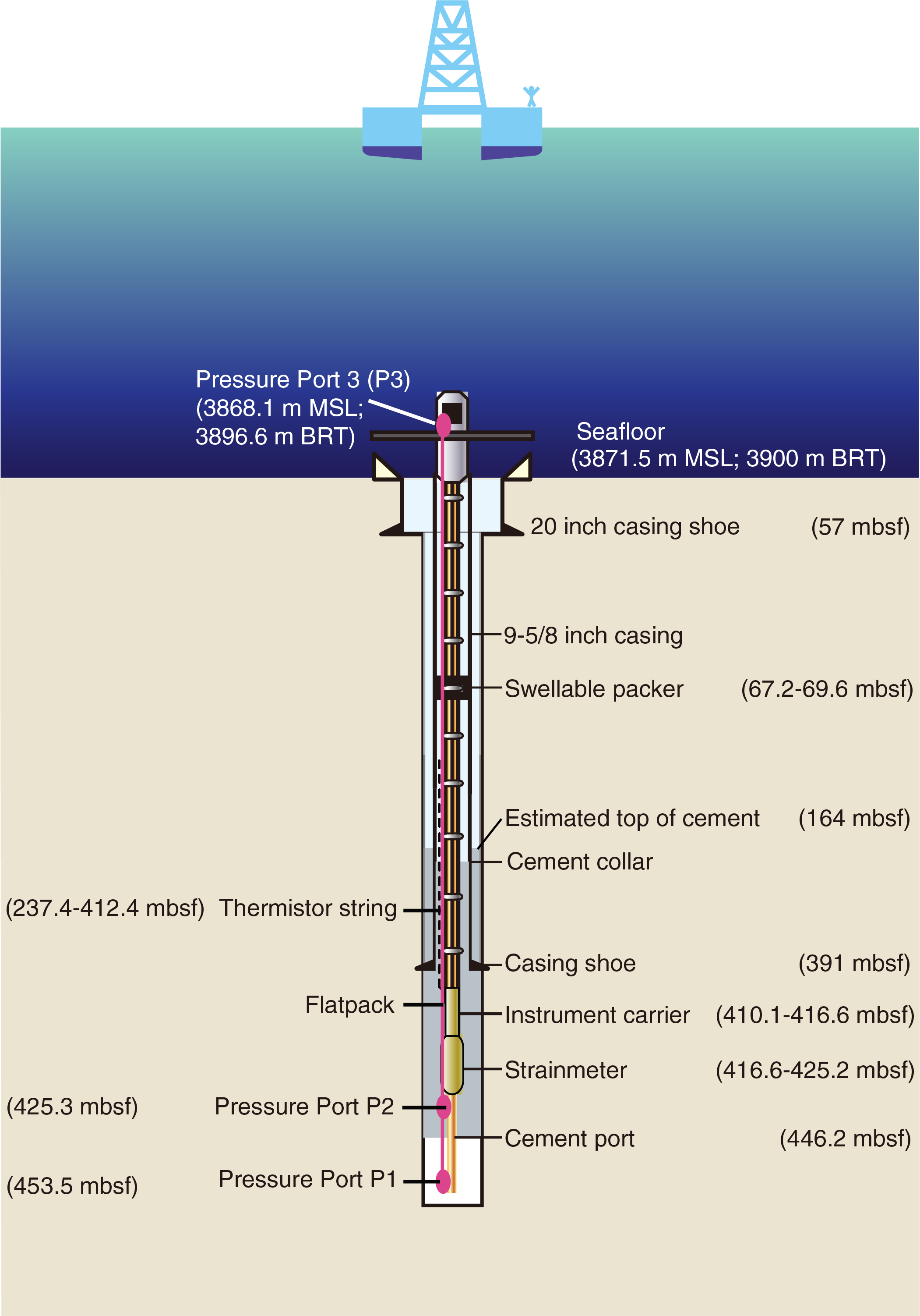
Figure F2. Hole C0006G LTBMS.
Observatory string instruments
The LTBMS instruments are listed here in detail from the bottom of the hole to the LTBMS CORK head. The PSU (on the CORK head) pressure ports are located in the lowermost portion of Hole C0006G.
Observatory PSU
The PSU is equipped with three Paroscientific Digiquartz pressure transducers. Two of the transducers connect to ¼ inch stainless steel tubing that terminates at two measurement points in the subseafloor, one ending in miniscreens and located below the cement (Pressure Port 1 [P1]) and the other located within the cemented interval (Pressure Port 2 [P2]) (Figure F2). The third transducer (Pressure Port 3 [P3]) measures pressure at the seafloor. The two subseafloor ¼ inch hydraulic tubings are housed in a urethane-coated flatpack umbilical that connects the monitored intervals to the LTBMS CORK head (Figure F2). A swellable packer and the cemented interval isolates the formation fluid and enables monitoring of in situ formation pressure once the response to drilling and open hole operations has dissipated. See Figure F3 for a schematic of the PSU and tubing configuration. Table T3 and Thermistor_SP_PSU.docx in CHECKLISTS in Supplementary material list the PSU instrument details.
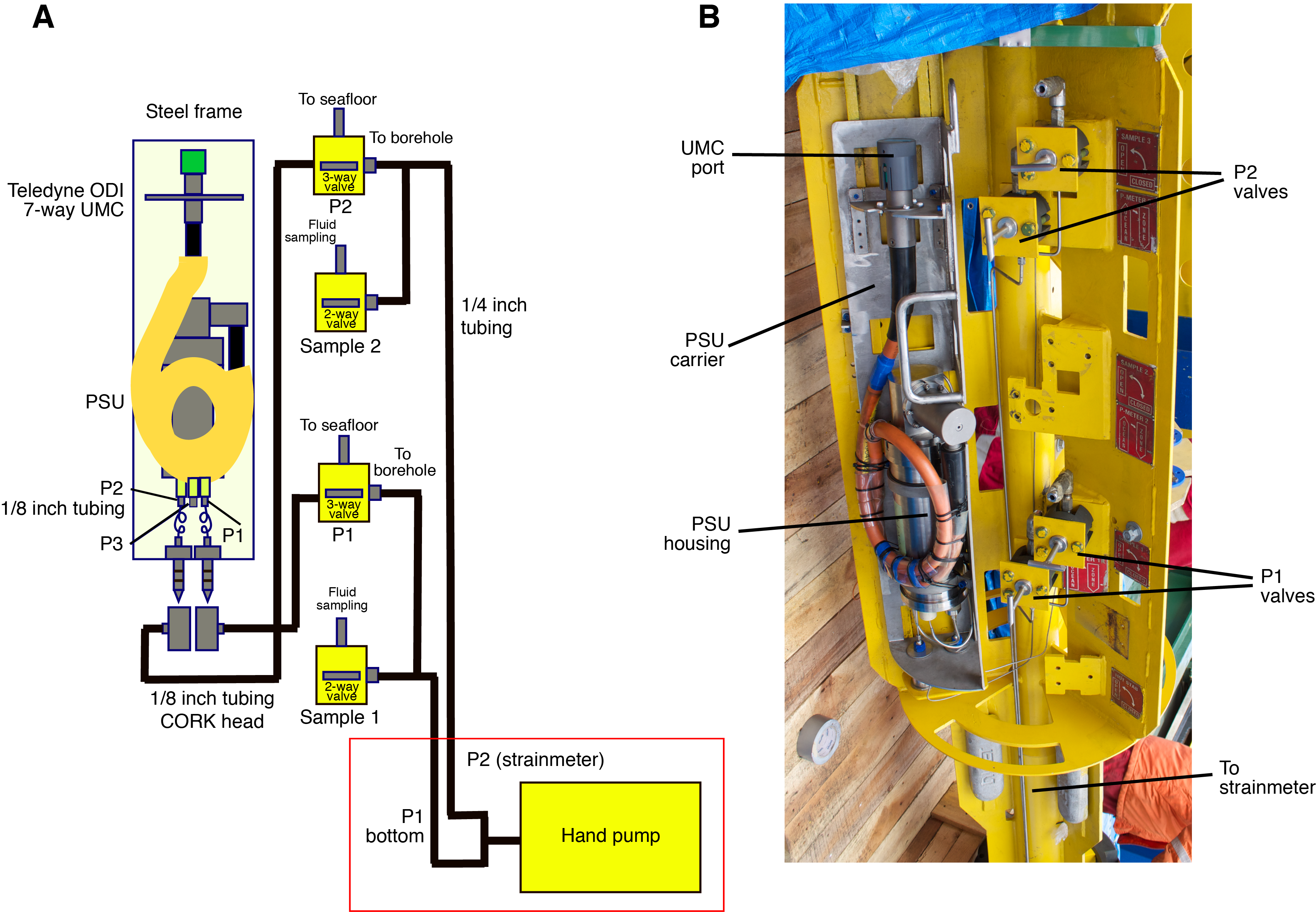
Figure F3. Pressure-sensing unit.
The first, lowermost monitoring interval (P1) is located at the bottom of the open borehole below the strainmeter, 8 m beneath the cemented interval (Figures F1, F2). Three 1 inch diameter miniscreens protect the ¼ inch stainless steel hydraulic tubing from clogging and are connected to tubing by a single manifold (Figure F4). The ¼ inch tubing is connected to ⅛ inch tubing that passes through the strainmeter and to the instrument carrier above. The miniscreen configuration maximizes the azimuthal coverage of the borehole while minimizing the possibility of screen obstruction.
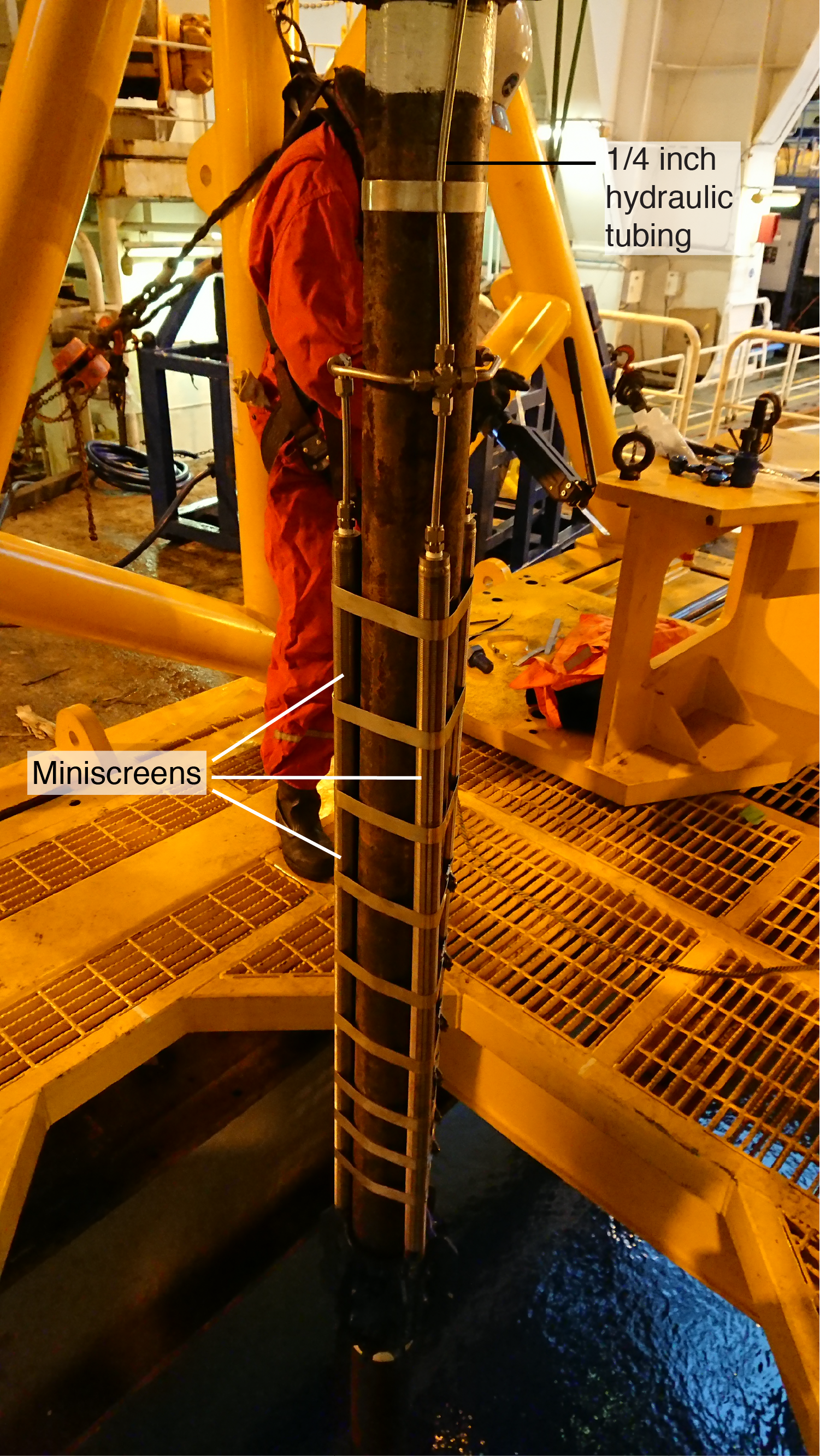
Figure F4. Tubing bullnose.
The PSU is attached to a steel frame and mounted within Bay 1 of the LTBMS CORK head (Figures F1, F3). The data logger in the PSU at the LTBMS CORK head can be accessed through an UMC with the same specifications as the set of three UMCs mounted in Bay 2 for the other instruments (see the following sections). The pin layout of the Teledyne ODI connector is compatible to its three counterparts and therefore allows the ROV pilot to use the same interface for communication and data download.
A series of pressure tests were performed in the laboratory and after the PSU was installed in Bay 1 at the LTBMS CORK head. During these tests, various problems were identified (see Table T4 for troubleshooting during PSU testing). All fittings and connections were checked and tightened prior to deployment, a procedure that needed to be completed multiple times before installation. Multiple tests performed in the laboratory ensured that the PSU was logging data correctly at both high (>24 V) and low (7.5–9 V) voltages.
The PSU used in Hole C0006G is set to log at 0.2 Hz when powered at <9 V (e.g., when it is running on battery power), with the sampling rate set to automatically increase to 1 Hz when the voltage exceeds 9 V. This increase occurred when the LTBMS was plugged into the 24 V power supply from the Dense Oceanfloor Network System for Earthquakes and Tsunamis (DONET) in March 2018.
A few days prior to deployment, the hydraulic tubing on the LTBMS CORK head was flushed, and the PSU was mounted on the LTBMS CORK head for further pressure tests to ensure that all of the plumbing and valves were configured correctly and pressure-tight. First, flushing was performed with a hand pump (Figure F3) to check that water flowed through the correct pathways for each valve setting, and then each of the three hydraulic tubes were individually pressurized for testing. During each test, the hydraulic tubing connecting the formation to the Paroscientific sensor was kept pressurized at 5–10 MPa for at least 3–24 h, ensuring that pressure varied only with temperature changes and not in response to leaks in the system. Once system integrity was confirmed, the tubing was depressurized and the tests were concluded.
Strainmeter
The strainmeter, cemented above the lowermost monitored pressure interval, was designed by Japan Agency for Marine-Earth Science and Technology (JAMSTEC) for deep-sea borehole installation. Figure F5 shows a schematic of the LTBMS strainmeter, and Table T5 lists instrument details. Similar to the Sacks-Evertson–type volumetric strainmeter, the LTBMS strainmeter measures the volume change of an oil-filled, cylindrical strain-sensing volume in response to the deformation of the surrounding formation (Sacks et al., 1971). Formation deformation transmits to the sensing volume through the cement, which fills the annulus between the formation and the strainmeter. This strainmeter was designed with a 168.3 mm sensing volume diameter, which is much larger than conventional land-based strainmeters (typically ~75 mm diameter). The strainmeter is 9.6 m long, including digitizer electronics and a transducer housing, chambers, joints, and the sensing volume (~2.8 m). It also incorporates tubing through its center so that cement can be pumped through the instrument, ultimately reaching the cement port on the bottom of the observatory for coupling to the formation.
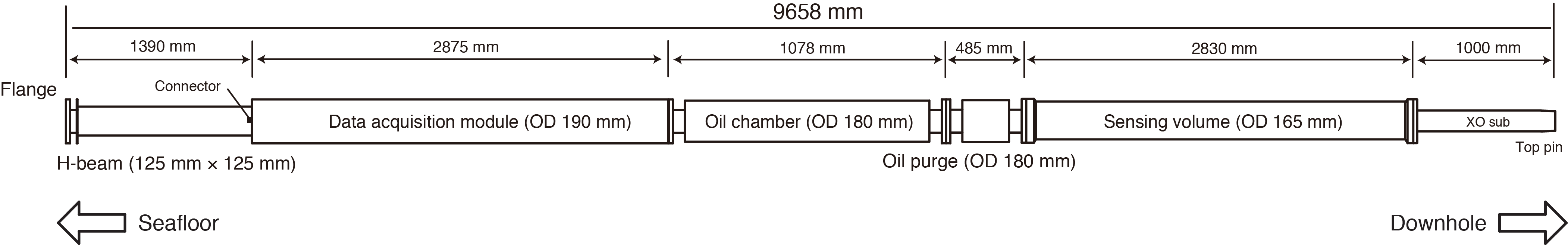
Figure F5. Strainmeter components and configuration.
The strainmeter is designed to withstand ambient pressures as high as 70 MPa, which is the maximum pressure the instrument may experience during transit through the water column to the borehole. The strainmeter is very sensitive to deformation because the bellows’ full measurement range of volume change is ~1 cm3, which corresponds to a strain of 3 × 10⁻⁵. While the strainmeter is being lowered from the ship, strain may exceed the full measurement range; therefore, a valve bypassing the bellows is installed and kept open to protect the sensor while the instrument is being deployed. After being cemented into position, a command issued through the acoustic modem will close the bypass valve and measurements will begin (see the following sections). The bypass valve also opens automatically when the instrument measures strains outside of the full measurement range. By opening the valve, the bellows is recentered to zero, resetting accumulated strain. The valve is then closed to resume strain measurements. The position of the bellows indicates a strain change, which is recorded by a digitizer in the strainmeter. Strain data are transmitted uphole by a sensor cable terminating in a UMC. A Paroscientific pressure transducer is also connected to the strain-sensing volume, and its pressure reading is used to check the status of other components, including the bypass valve. A three-component accelerometer is also included within the strainmeter. A controller inside the strainmeter regulates the digitizing displacement of the bellows, valve position (open or closed), and acceleration. The cable transmits serial data and power (24–30 V DC) to the strainmeter.
Vortex-induced vibration (VIV) is a common effect of the strong Kuroshio Current (Kitada et al., 2013), and operating in the current causes wear and damage to equipment and sensors. VIV exhibits a dominant frequency of 3–15 Hz and a maximum acceleration of 2G. Vibration tests approximating these conditions were performed to confirm that the strainmeter design is capable of withstanding these vibrations during installation. These tests were applied to all strainmeter components and electronics. High-pressure tests (as high as 60 MPa) successfully showed that the valve, bellows, and sensor plumbing systems function correctly under pressure.
Instrument carrier and sensor orientation
Previous experience with deploying an LTBMS near the Nankai Trough in the strong Kuroshio Current demonstrated the need for a strong frame to shield the instruments from damaging forces. During Expedition 380, however, the Kuroshio Current was never closer than 90 km to Hole C0006G, leaving calm waters for a safer deployment and a speedy drilling program. Nonetheless, the instruments were housed within an H-beam–shaped instrument carrier designed to hold the delicate components and protect them during deployment. The carrier includes the borehole instruments, sensor cables, and hydraulic tubing. A 190 mm diameter, 30 mm thick flange at each end provides sufficient strength against bending and tension loading. Cables, hydraulic tubing, and the thermistor string (see following section) all pass through six preformed slits in each flange. Six M16 high-tension bolts with self-locking nuts connect the flanges at each end. A schematic of the instrument carrier with installed instruments is shown in Figure F6. The orientation of the instruments is shown in Figure F7.
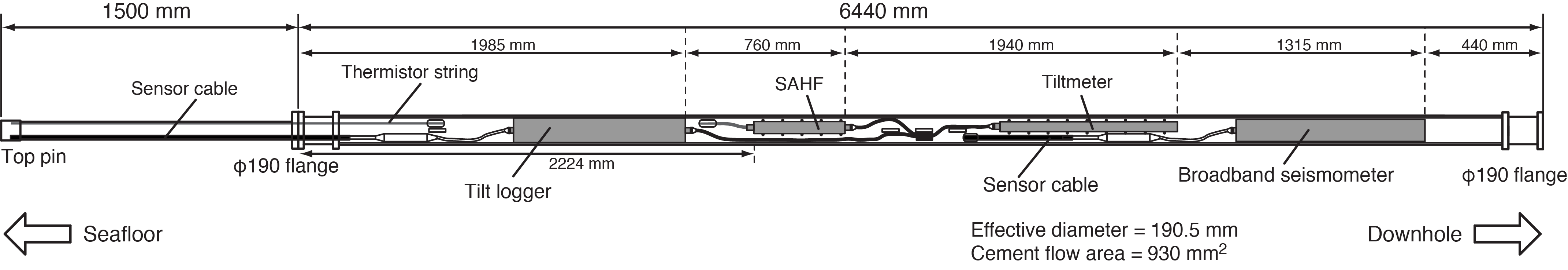
Figure F6. Instrument carrier.
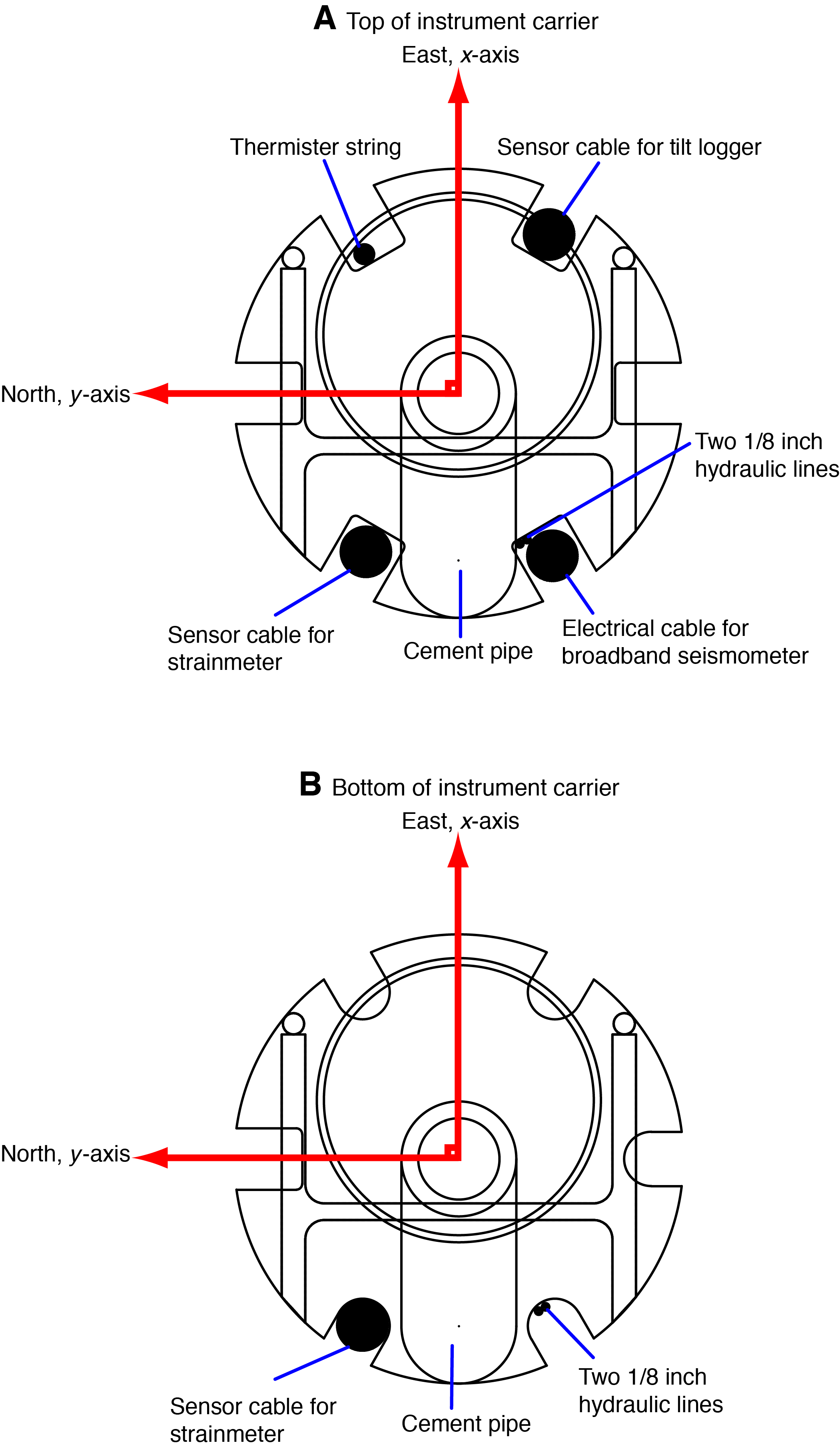
Figure F7. Instrument carrier flanges.
The broadband seismometer (CMG3T) and tilt combo were installed on the instrument carrier using steel wrap-around bands with lock-nut fasteners (Figure F8). Fiberglass-reinforced plastic (FRP) spacers isolated the sensor casings from the instrument carrier. All cables and hydraulic tubing and the thermistor string were connected to the instrument carrier using steel bands and plastic zip-ties.
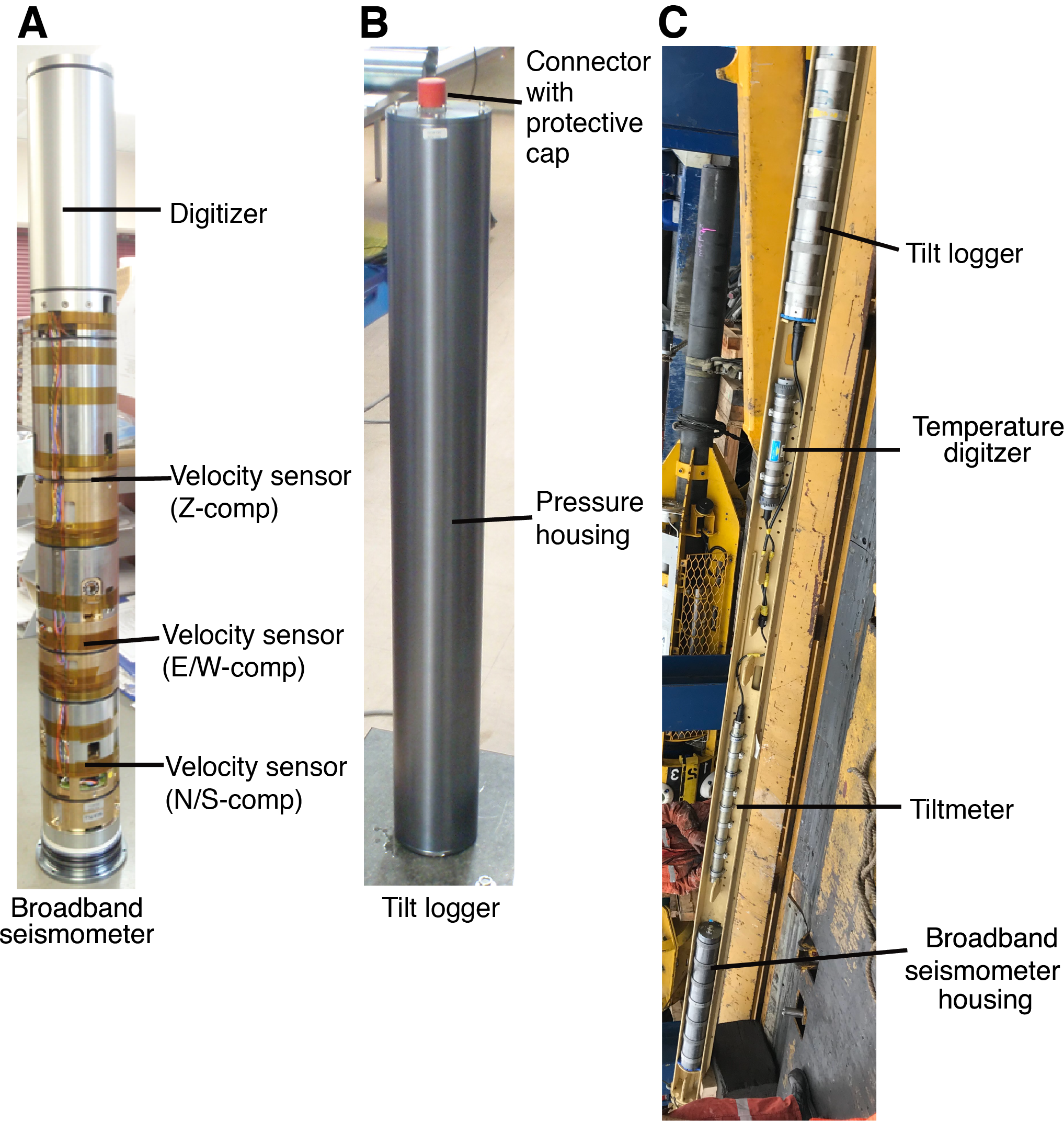
Figure F8. Sensors and instrument carrier.
Broadband seismometer
The CMG3T broadband seismometer installed in Hole C0006G is the same design as the one installed in Hole C0010A during Expedition 365 (Saffer et al., 2017). Figure F8 shows a schematic of the broadband seismometer. Table T6 lists detailed information about the seismometer. The seismometer’s titanium housing contains three sensors that measure ground velocity on three orthogonal (x-, y-, and z-) axes in the frequency range between 1/360 and 50 Hz. The seismometer is mounted near the bottom of the instrument carrier, which is cemented in the hole to ensure good coupling to the formation. Each sensor has a motorized leveling mechanism so that the sensors are functional within 4.5° of tilt.
Each sensor has a proof mass supported on a pivot, and each pivot is suspended by a leaf spring while measurements are active. The structurally weak pivot design assures very high sensitivity to ground motion. To protect these weak pivots from damage during transport, the proof masses are motion-locked. Locking of proof masses, leveling of sensors, and digitization of x-, y-, and z- ground motion is performed by a DM24 digitizer installed in the titanium housing. Resistance (~15 Ω) causes the 420 m borehole cable to dissipate power over its length; therefore, higher voltages (~30 V) need to be applied so that the seismometer can receive sufficient power to run the motor.
Tilt combo
The tilt combo installed on the instrument carrier contains three components: the LILY tiltmeter, the tilt logger, and the SAHF temperature digitizer (Figure F9). The SAHF temperature digitizer is connected to the thermistor string and is attached adjacent to the tilt combo on the instrument carrier. All instruments lie just above the broadband seismometer.
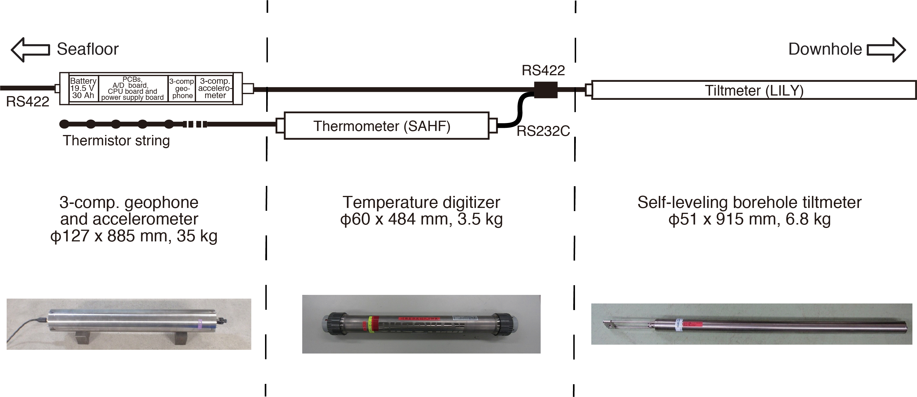
Figure F9. Tilt combo component sensors.
Instrument specifications
A schematic diagram of the tilt combo is shown in Figure F9, and Table T7 contains specific information on each tilt combo instrument. The tilt combo measures both ground motion and crustal deformation, with crustal deformation detected by the LILY tiltmeter instrument. For ground motion, one titanium housing unit contains the three-component geophones, the three-component accelerometer electrical boards, a CPU board, an analog to digital (A/D) conversion board, a power supply board, and internal batteries. Signals from the three-component geophone and accelerometer are digitized by an A/D converter on the A/D conversion board. The A/D conversion board has a calibration circuit that transmits electrical pulses to the geophone.
The tiltmeter and SAHF temperature digitizer each have their own A/D converters and titanium housings mounted on the instrument carrier. Each is connected to the CPU board through an electrical cable using dry-mate connectors. The tiltmeter, SAHF temperature digitizer, and accelerometer can individually be set to active or sleeping modes by switching electrical relays on the power supply board. All data are merged on the CPU board in standalone acquisition mode, in which data are stored to a mounted SD memory card. The CPU clock time can be synchronized to the GPS 1 pulse/s signal (Table T7).
Additional sets of instruments were prepared as backups for the primary sets. These sensors included two sets of tilt logger pairs (Modules 2 and 4), two sets of tiltmeters, and two sets of temperature digitizers (Numbers 3 and 4).
A series of tests was performed on each tilt combo to ensure its functionality. Initial testing took place in the laboratory and involved hooking up the individual tilt combo components together in the configuration shown in Figure F9 and powering them with an external power supply. The tilt combos (both primary and spare) were left to record for 12–96 h, ensuring that enough data were collected to check logging ability and data quality. The spare tilt combo encountered the same problem multiple times during initial testing: the instrument would suddenly stop recording after an unspecified amount of time. Troubleshooting revealed a loose wire in a connector, which was shorting out the tilt combo. When repaired, the spare began functioning normally. After initial testing, the primary tilt combo instruments were loaded into the instrument carrier, reconnected, and tested again.
Thermistor string
The thermistor string is designed for monitoring temperature in the borehole for long periods of time. The string contains five thermistors placed at intervals along an electrical cable, allowing for monitoring over 167 m of the Hole C0006G LTBMS (Figure F2). A schematic of the thermistor string and individual thermistor spacing are shown in Figure F10.

Figure F10. Thermistor string layout.
Electrical wires are covered by a hydrolytically stable polyether-based material, and the thermistors and connector are molded using the same material as the cable. The thermistor string is connected to the SAHF temperature digitizer and mounted within the instrument carrier. See Thermistor_SP_PSU.docx in CHECKLISTS in Supplementary material for temperature calibration information.
Data recording before DONET connection and future ROV operations
After the LTBMS was installed in Hole C0006G, the PSU began recording hydrostatic pressure (valves open to the ocean) using its own onboard battery power. The water depth for Hole C0006G exceeds the operation depth of the R/V Chikyu’s onboard ROV. With the lack of an on-site data recorder and power source, the tilt combo, strainmeter, and seismometer remained off-line until the LTBMS was connected to DONET. Time synchronization for the entire observatory was made upon connection to DONET, and power was provided to all sensors, allowing for the full suite of measurements to begin as of 27 March 2018. The UMC for the PSU was accessible by the JAMSTEC ROV Hyper-Dolphin for pressure data recovery, as well as the UMCs for the other instruments for connection to DONET (Figure F1; note the hooks that lie just below the UMC ports in Bay 2 for ROV use). An ROV platform attached to the LTBMS CORK head allows for easier ROV access during future underwater operations.
Acoustic modem
An acoustic modem system temporarily replaced the ROV connection before connection to DONET, allowing communication with the installed LTBMS instruments through acoustic signals. The acoustic modem can control the electrical power fed to the borehole instruments and measure supplied/internal current and voltage. Furthermore, the acosic modem can obtain small data logs and instrument health information an can control the main functions of the downhole instruments (i.e., turning sensors on/off, checking the conditions of the pivot masses within the seismometer, etc.). Initial laboratory testing of acoustic communications proved successful, with each sensor responding promptly with appropriate data, functions, and sensor condition. Secondary communication tests during LTBMS preparation assured the acoustic modem’s functionality. A schematic diagram of the acoustic modem in the CORK head is shown in Figure F5, and Table T8 contains specific information on the instrument.
During installation, LTBMS sensor conditions were checked through acoustic modem communication. The receiver of the acoustic modem is connected by UMCs to the borehole instruments, and the transmitter of the acoustic modem was attached to the underwater TV.
References
Becker, K., Kinoshita, M., Toczko, S., and the Expedition 380 Scientists, 2018. Supplementary material, https://doi.org/10.14379/iodp.proc.380supp.2018. Supplement toBecker, K., Kinoshita, M., Toczko, S., and the Expedition 380 Scientists, NanTroSEIZE Stage 3: Frontal Thrust Long-Term Borehole Monitoring System (LTBMS).Proceedings of the International Ocean Discovery Program, 380: College Station, TX (International Ocean Discovery Program). https://doi.org/10.14379/iodp.proc.380.2018
Expedition 332 Scientists, 2011. Expedition 332 summary. InKopf, A., Araki, E., Toczko, S., and the Expedition 332 Scientists, Proceedings of the Integrated Ocean Drilling Program, 332: Tokyo (Integrated Ocean Drilling Program Management International, Inc.). https://doi.org/10.2204/iodp.proc.332.101.2011
Kitada, K., Araki, E., Kimura, T., Mizuguchi, Y., Kyo, M., Saruhashi, T., Sawada, I., Namba, Y., and Kinoshita, M., 2013. Field experimental study on vortex-induced vibration behavior of the drill pipe for the ocean borehole observatory installation. IEEE Journal of Ocean Engineering,38(1):158–166. https://doi.org/10.1109/JOE.2012.2213973
Kopf, A., Saffer, D., Toczko, S., Araki, E., Carr, S., Kimura, T., Kinoshita, C., Kobayashi, R., Machida, Y., Rösner, A., and Wallace. L.M., 2017. Expedition 365 summary. With contributions by S. Chiyonobu, K. Kanagawa, T. Kanamatsu, G. Kimura, and M.B. Underwood. InSaffer, D., Kopf, A., Toczko, S., and the Expedition 365 Scientists, NanTroSEIZE Stage 3: Shallow Megasplay Long-Term Borehole Monitoring System.Proceedings of the International Ocean Discovery Program, 365: College Station, TX (International Ocean Discovery Program). https://doi.org/10.14379/iodp.proc.365.101.2017
Sacks, I.S., Suyehiro, S., Evertson, D.W., and Yamagishi, Y., 1971. Sacks-Evertson strainmeter: its installation in Japan and some preliminary results concerning strainsteps. Papers in Meteorology and Geophysics,22:195–208.
Saffer, D., Kopf, A., Toczko, S., Araki, E., Carr, S., Kimura, T., Kinoshita, C., Kobayashi, R., Machida, Y., Rösner, A., and Wallace, L.M., 2017. Site C0010. With contributions by S. Chiyonobu, K. Kanagawa, T. Kanamatsu, G. Kimura, and M.B. Underwood. InSaffer, D., Kopf, A., Toczko, S., and the Expedition 365 Scientists, NanTroSEIZE Stage 3: Shallow Megasplay Long-Term Borehole Monitoring System.Proceedings of the International Ocean Discovery Program, 365: College Station, TX (International Ocean Discovery Program). https://doi.org/10.14379/iodp.proc.365.103.2017
1 Kinoshita, M., Becker, K., Toczko, S., Edgington, J., Kimura, T., Machida, Y., Roesner, A., Senyener, B., Sun, T., 2018. Expedition 380 methods. In Becker, K., Kinoshita, M., Toczko, S., and the Expedition 380 Scientists, NanTroSEIZE Stage 3: Frontal Thrust Long-Term Borehole Monitoring System (LTBMS). Proceedings of the International Ocean Discovery Program, 380: College Station, TX (International Ocean Discovery Program). https://doi.org/10.14379/iodp.proc.380.102.2018
2Expedition 380 Scientists’ affiliations.
This work is distributed under the Creative Commons Attribution 4.0 International(CC BY 4.0) license. 