Becker, K., Kinoshita, M., Toczko, S., and the Expedition 380 Scientists
Proceedings of the International Ocean Discovery Program Volume 380
publications.iodp.org
https://doi.org/10.14379/iodp.proc.380.103.2018

Site C00061
M. Kinoshita, K. Becker, S. Toczko, J. Edgington, T. Kimura, Y. Machida, A. Roesner, B. Senyener, and T. Sun2
Keywords: International Ocean Discovery Program, IODP, Chikyu, Expedition 380, Site C0006, accretionary prism, frontal thrust, prism toe, Shikoku Basin, Nankai Trough, borehole observatory, long-term borehole observatory, LTBMS, Nankai Trough Seismogenic Zone Experiment, NanTroSEIZE, Dense Oceanfloor Network System for Earthquakes and Tsunamis, DONET, tsunami, tsunamigenic fault
MS 380-103: Published 20 December 2018
Introduction
International Ocean Discovery Program (IODP) Expedition 380 returned to Nankai Trough Seismogenic Zone Experiment (NanTroSEIZE) Integrated Ocean Drilling Program Site C0006 in the toe of the Nankai accretionary prism ~2 km landward of the trench axis (Figures F1, F2, F3). The sole objective of Expedition 380 was the riserless installation of a long-term borehole monitoring system (LTBMS) in Hole C0006G to ~450 meters below seafloor (mbsf) in the hanging wall above the plate boundary fault. Site C0006 was logged and cored during two of the initial NanTroSEIZE expeditions, 314 (Expedition 314 Scientists, 2009) and 316 (Expedition 316 Scientists, 2009). The LTBMS was of the same general design as the borehole observatories previously installed in Integrated Ocean Drilling Program Hole C0010A farther up the accretionary prism (Kopf et al., 2017) and Integrated Ocean Drilling Program Hole C0002G at the southeastern edge of the Kumano Basin above the prism (Expedition 332 Scientists, 2011). The LTBMS observatories in Holes C0002G and C0010A are already connected to the Dense Oceanfloor Network System for Earthquakes and Tsunamis (DONET) (http://www.jamstec.go.jp/donet/e), and the LTBMS in Hole C0006G was successfully connected in March 2018, shortly after Expedition 380. The transect of these three observatories should provide unprecedented resolution of the state of stress and strain in the leading edge of the overriding plate from the near-trench region to the seismogenic zone on a wide range of timescales, with near–real time data available to the scientific community.
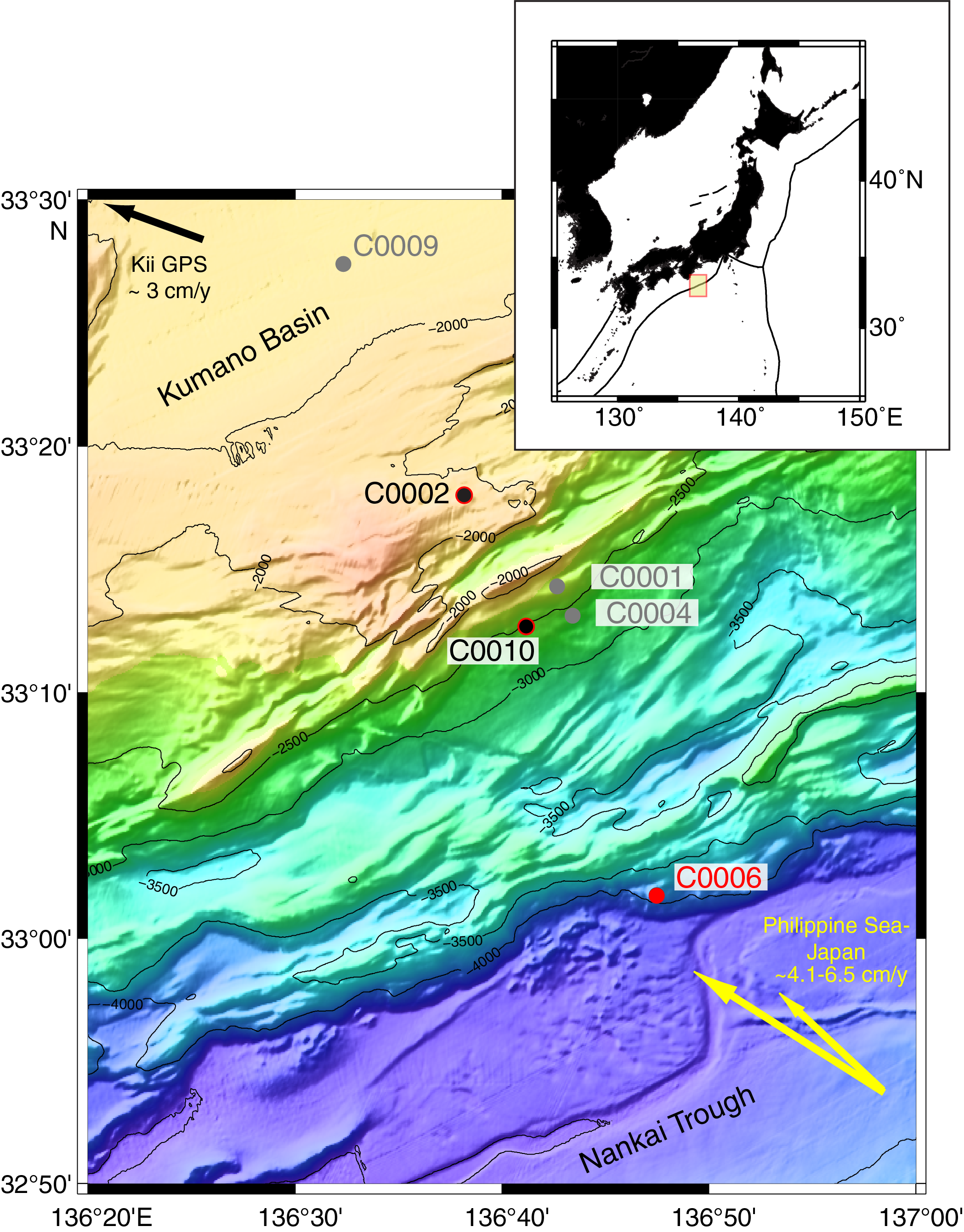
Figure F1. Site locations.

Figure F2. Interpreted seismic cross section and LTBMS site locations.

Figure F3. Interpreted seismic depth section.
The LTBMS in Hole C0006G shares the same general design as the two LTBMS systems previously installed in Holes C0002G and C0010A (see the Expedition 380 methods chapter [Kinoshita et al., 2018]). It includes an array of sensors designed to monitor slow crustal deformation (e.g., strain, tilt, and pore pressure as a proxy for strain), seismic events covering strong motion to very low frequency earthquakes, hydrologic transients associated with strain events, ambient pore pressure, and temperature. To ensure the long-term and continuous monitoring necessary to capture events that occur over a wide range of timescales, the borehole observatory was connected to DONET in March 2018 to provide power and allow for higher sampling rates than can be achieved in a standalone mode. The data from all three LTBMSs can be viewed and downloaded at the J-SEIS open-access observatory data portal (http://join-web.jamstec.go.jp/join-portal/en). Data from the Site C0002 LTBMS can also be accessed at http://offshore.geosc.psu.edu/about.
Selection of LTBMS monitoring zones from previous results at Site C0006
Expedition 380 conducted no new coring or logging. Site C0006 was originally drilled during Expedition 314 with measurement while drilling (MWD) and then logging while drilling (LWD) to 885.5 mbsf in two holes ~30 m apart (Expedition 314 Scientists, 2009). Four holes were cored at this site during Expedition 316 to a maximum of 603 mbsf (Expedition 316 Scientists, 2009). The LTBMS design and operational plan for Expedition 380 were based on these previous results, especially the continuous logging profiles. Therefore, the new LTBMS Hole C0006G was positioned midway between the two Expedition 314 MWD/LWD Holes C0006A and C0006B.
From examination of the Site C0006 cores, Expedition 316 Scientists (2009) identified three primary lithologic units (Figure F4). Unit I extends from the seafloor to ~27 mbsf and comprises Pleistocene trench to slope transition facies. Unit II is composed of Pleistocene trench deposits divided into four subunits based mainly on variations in silt and sand content, with significant repetition of sequences caused by numerous thrust faults. It extends to ~407 mbsf in Hole C0006E and ~450 mbsf in Hole C0006F. Subunit IIA comprises mainly sand-dominated trench wedge deposits, Subunit IIB comprises mixed sand-mud trench wedge deposits, Subunit IIC comprises mud-dominated trench wedge deposits, and Subunit IID comprises deep-marine basin to mud-dominated trench transition deposits. Unit III comprises late Miocene to Pleistocene deep-marine basin deposits.
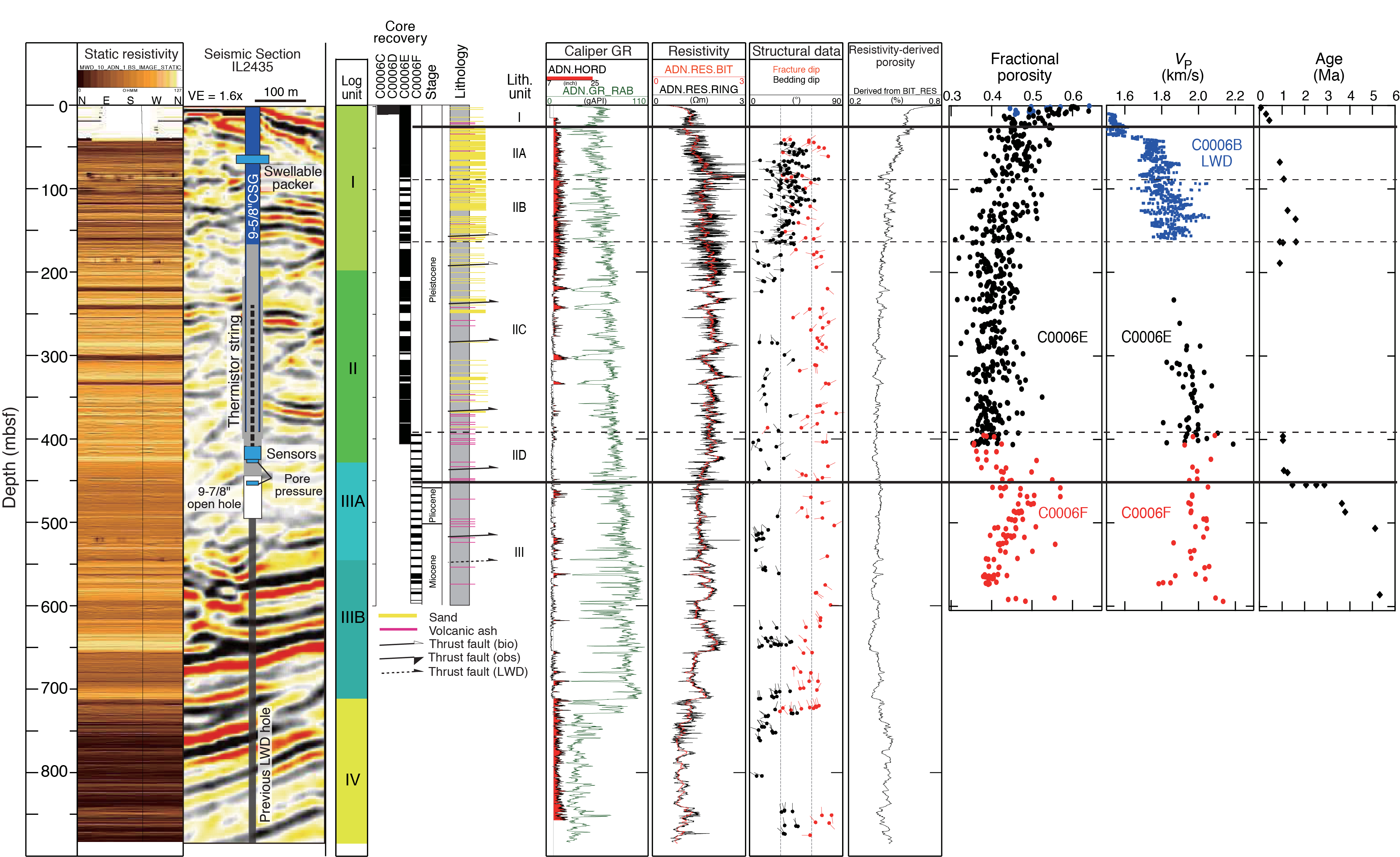
Figure F4. Seismic section and logging and coring results.
Four primary logging units (Figure F4) were identified based on differing trends and LWD log responses (Expedition 314 Scientists, 2009). Logging Unit I (0–197.8 m LWD depth below seafloor [LSF]) was interpreted to be sandy and muddy deposits. Logging Unit II (197.8–428.3 m LSF) was interpreted to be mud with occasional thick sand layers. Logging Unit III (428.3–711.5 m LSF) was identified as alternating beds of mud and sand and is divided into two subunits. The boundary between Logging Units II and III might be a fault zone (Figure F4). Logging Unit IV (711.5 m LSF to total depth) was interpreted to be underthrust, coarse trench-fill sediments. The main frontal thrust was identified by a sudden decrease in gamma ray values (from ~90 to 20–50 gAPI) across the Logging Unit III/IV boundary.
Based on these results, the target zone for the main LTBMS instrument package (strainmeter/seismometer/tiltmeter/pressure sensor) was selected in the deepest part of Logging Unit II at ~410–425 mbsf (Figure F4). The formation in this interval was expected to be relatively competent mudstone suitable for monitoring formation pressure and deformation in the hanging wall at the frontal toe of the prism. With the main package at 410–425 mbsf, the LTBMS design also allowed for (1) a deeper pressure monitoring screen in the open hole near the boundary between Logging Units II and III and (2) placement of the thermistor cable from ~400 to 250 mbsf spanning much of Lithologic Subunit IIC.
Operations
Expedition 380 began in the port of Shimizu, Shizuoka Prefecture (Japan), on 12 January 2018. The first few days were spent quayside, loading cargo and supplies. The science party boarded the D/V Chikyu on 12 January and participated in the shipboard prespud meeting on 14 January. The Chikyu sailed from Shimizu at 0900 h (local time; UTC + 9 h) on 15 January and arrived on location at Site C0006 by 0300 h on 16 January.
Site C0006
After arrival at Site C0006, four transponders were dropped (free fall) at the site. Making up and running the 20 inch casing began at 0845 h on 16 January 2018 (Table T1). The inner string bottom-hole assembly (BHA), composed of the jetting assembly and the drill-ahead tool (DAT) (Table T2), was made up and run into the casing at 2100 h. Make-up was paused for 1.5 h starting at 2300 h on 16 January to troubleshoot the closed-circuit TV (CCTV) camera system. Once resolved, the string and DAT were again lowered into the wellhead on the working cart in the moonpool from 0100 to 0230 h on 17 January. After picking up the casing with the internal BHA and confirming that the jetting BHA protruded 5 inches from the casing shoe, trouble with the CCTV halted all activities from 0400 to 0530 h. At 0530 h, the 20 inch casing was run to 3800 m BRT. Running stopped at 1815 h to install the underwater TV (UWTV) on the drill pipe. The UWTV was run down to 7 m above the 20 inch casing shoe by 2145 h. The vessel shifted to tag the seabed. At 2215 h, the Hole C0006G location and water depth (3900 m BRT; 3871.5 m MSL) were tagged and confirmed before jetting in.
Hole C0006G
Jetting in for Hole C0006G commenced at 2215 h, reaching 3965 m BRT by 0345 h on 18 January. At this point, the UWTV was retrieved after confirming that the DAT was in good condition and before continuing to drill down. The UWTV reached the surface at 0700 h, and drilling down commenced. After performing a wiper trip from 399 to 457 mbsf, the hole was swept and spotted with saltwater gel. The drill string was picked up to 66 mbsf while the UWTV was run to 10 m above the wellhead. The DAT was recovered, and the UWTV was again recovered in the moonpool. The DAT BHA was pulled out of the hole to the surface and, once that was completed at 2300 h on 19 January, the 9⅝ inch casing was made up and run. Once the casing reached 388 m BRT at 0745 h on 20 January, the casing hanger running tool (CHRT) was picked up and connected to the 9⅝ inch casing hanger. The casing was run down and hung in the moonpool from the working cart while the CHRT was made up and attached to the top of the casing. Once the Activation Kit was charged, the casing, CHRT, and Activation Kit were all run down to 1410 m BRT by 1945 h. The UWTV was opened and set around the drill pipe and then run down to the Activation Kit so that the UWTV cameras could monitor the kit’s pressure. The casing and CHRT were all run down to 3854 m BRT in preparation for reentering Hole C0006G. The wellhead was found, and the casing was run in at 0630 h on 21 January. Once the BHA reached 373 mbsf, the cement stand was made up and preparations for cementing began. Cementing the 9⅝ inch casing began at 2200 h on 21 January and was completed by 0145 h the next morning. Once the cementing was finished, the Activation Kit was unlocked from the casing hanger, the entire string was pulled out of the hole back to 4297 m BRT (397 mbsf), and the UWTV was recovered to the surface.
Once the UWTV was back on the working cart in the moonpool, the drill string was pulled out of the hole to prepare for running the bicenter bit BHA to drill out the cement and deepen the hole. The bit was made up and run in the hole at 1515 h on 22 January. By 0400 h on 23 January, the BHA reached 3853 m BRT. The drillers broke circulation in the string to run the UWTV for reentry in Hole C0006G. The UWTV reached 7 m above the bit at 0530 h, and reentry was completed by 0745 h. The UWTV was recovered in the moonpool at 0930 h. The BHA was run down to 4159 m BRT (259 mbsf) and then washed down to 4223.5 m BRT (323.5 mbsf) to begin drilling out cement. Several Hydrolift Power Swivel (HPS) stalls were observed. At 1445 h, drilling stopped, and the BHA was pulled out of the hole. The bicenter bit BHA was finally laid down at 0200 h on 24 January. The bicenter bit showed some damage, and after >3 h of drilling no appreciable advance was observed. Therefore, a drill-out-cement BHA was made up and run in the hole at 0200 h. The UWTV was lowered to 7 m above the bit, and both it and the bit were run down toward the seafloor. After the bit and the UWTV reached 3895 m BRT, the vessel was shifted to well center, and the Hole C0006G wellhead was reentered at 1400 h on 24 January. The UWTV was again recovered to the moonpool working cart before washing down to the top of cement at 325 mbsf. Drilling out the cement began again at 1715 h, and drilling and reaming continued to 409 mbsf. Five cubic meters (in two separate actions) of saltwater gel were used to sweep out the hole, which was ended by spotting another 5 m3 of saltwater gel. A wiper trip from 409 to 399 mbsf was followed by cleaning and sweeping out the 5 m3 of saltwater gel. The drill-out-cement BHA was pulled out of the hole to the surface and laid down at 0915 h on 25 January. The derrick stopped for HPS and traveling block maintenance while the vessel moved 1 nmi from well center, which was completed by 2145 h on 25 January.
The bicenter bit (Table T2) was made up and run to 3870 m BRT by 0830 h on 26 January. The UWTV was then run down to 7 m above the bit to help with wellhead reentry. After reentering at 1130 h, the bit was run to 407 mbsf. The bit was pulled back to 383 mbsf, and then there was a pause until 1530 h, by which time the UWTV was recovered in the moonpool. The bicenter bit BHA drilled to total depth (495 mbsf) by 2030 h, and the hole was swept twice with 10 m3 of saltwater gel and spotted with another 10 m3 of saltwater gel. A wiper trip to 393 mbsf was completed by 2145 h and showed no excessive drag, indicating that the hole was in good condition. Another sweep and spotting regimen was completed, and a special Protect Zone treatment by Schlumberger was put down at 2400 h on 26 January. Another sweep and spotting regimen was completed before pulling out of the hole and laying down the bicenter bit BHA at 1145 h on 27 January. A scraper run to confirm the casing section was uncontaminated by any cement was finished at 0830 h on 28 January. Once the scraper runs were complete, the remotely operated vehicle (ROV) platform was made up on the working cart in the moonpool in preparation for running with the UWTV. The UWTV with ROV platform began its run at 1330 h on 28 January; landing and confirmation of locking on the wellhead was visually confirmed by UWTV camera and slack off was checked. The two downward-looking cameras each have a light, and both lights failed. The remaining upward-looking camera and light were tilted downward to observe the ROV platform landing. The UWTV was recovered to the surface at 1800 h. The scraper BHA was then pulled out of the hole, and it was laid down at 0200 h on 29 January.
LTBMS completion run preparation started on 29 January with assembling the bull nose, the miniscreen hydraulic port (Port 1), and the cement port on the 3.5 inch tubing backbone of the LTBMS observatory. At 1230 h on 29 January, the strainmeter and instrument carrier were run down to the moonpool cart and the completion guide roller (CGR) working platform on the blowout preventer (BOP) cart, where the sensors were connected to data and power cables. The hydraulic line from Port 1 was connected to a flatpack that was run all the way up to the LTBMS CORK head where the pressure-sensing unit (PSU) was installed. Cable attachments, tie bands, and metal straps were used to secure the hydraulic line to the strainmeter and instrument carrier. Once the strainmeter and other sensors reached the CGR and the sensor cables were attached, a communication test of each sensor cable was performed; all sensors were confirmed to be healthy by 1730 h. The assembly was run into the moonpool to 147 m BRT and then to 409 m BRT, pausing at each stage for another sensor check. At 1400 h on 30 January, the swellable packer was prepared to pass the sensor cables through passages cut into the packer. Preparation was finished at 1630 h, and the sensors were checked again. When this test was successfully completed, the tubing, sensor cables, and flatpack were all run into the moonpool to 448 m BRT, pausing for the final make up and running of the LTBMS CORK head to the rotating guide roller (RGR).
The LTBMS CORK head preparation began with terminating the hydraulic flatpack to the PSU valves and Swagelok hydraulic lines and was completed on 31 January at 0045 h. The three sensor cables were measured and prepared for cutting and then termination with underwater mateable connectors (UMCs) by the Teledyne ODI engineers. The cables were cut, and the connections to the sensors were checked and run into the termination van at 0430 h. ODI engineers then started the molding, soldering, and termination process. After the initial molding and soldering, a sensor communication test confirmed good communication and the termination proceeded. Termination was completed at 0015 h on 1 February, and another sensor communication check confirmed good connection through the UMCs to the sensors. The terminated sensor cables were moved to the BOP cart, and wrapping the sensor cables onto the LTBMS CORK cable bay began at 0100 h. After this was finished, another communication check confirmed that the strainmeter and tilt combo communications were good; the seismometer, however, could not receive any commands. Investigation and troubleshooting began at 0600 h. At 1500 h, the decision was made to cut the ODI connection. Checking sensor communication with the bare cable found that communication was good. Re-termination of the seismometer sensor cable with the only spare ODI UMC splice kit was completed at 0730 h on 2 February. Final sensor checks confirmed that communication with the seismometer was fully functional (sending commands and receiving correct responses). The reterminated cable was fixed to the cable bay of the LTBMS CORK, and all UMCs were fixed to the acoustic modem bay. Once fixed, the connection to the acoustic modem for each sensor cable was completed, and then sensor checks through the acoustic modem were performed. These checks were completed at 1230 h, and the LTBMS CORK head was run into the moonpool for 5 min with all three-way pressure valves set to “OCEAN” so that remaining air could be bled out and the hydraulic lines could be filled with seawater. The LTBMS CORK head was then picked up, the two-way sampling valves were closed, and all valve handles were fixed in position with plastic tie wraps. The CORK head was set on the working cart so that the Activation Kit could be picked up and charged with N2 and BOP fluid. These preparations were finished at 1930 h, and the casing (CSG) hanger, Activation Kit, and hydraulically activated running tool (HART) were run into the moonpool to 1400 m BRT. Running was paused to prepare the UWTV for diving, so the scientists performed another sensor check with the acoustic modem. At 0115 h on 3 February, the UWTV reached the Activation Kit and checked to see that the pressure charger was maintaining pressure. Once the pressure was visually confirmed by the UWTV cameras, running the CSG hanger and UWTV continued to 2000 m BRT, where the Activation Kit pressure was checked again. The check was completed at 0400 h, and the CSG hanger was run to 3880 m BRT, near the seafloor, and was paused to let the UWTV catch up. During this pause, scientists took the opportunity to check the sensors before reentering Hole C0006G; all sensors remained healthy. When the UWTV reached the Activation Kit, a circulation test was run; a small leak was discovered in the strainmeter assemblage, possibly from an imperfect or cracked weld on the cement bypass conduit. After discussion among the offshore superintendent (OSI), offshore installation manager (OIM), and Co-Chief scientists, it was decided that this leak would not impact cementing.
The wellhead was reentered at 0930 h on 3 February, and the LTBMS assembly was slowly run into the wellhead; the LTBMS CORK head landed at 1615 h. Postlanding cementing commenced after a final communication and health check with the sensors to confirm that none of them had been affected by reentering. All sensors were healthy. At 2100 h, the UWTV sent the release command by acoustic modem to the Activation Kit. Neither this command nor a following command activated the release mechanism, so mechanical release was attempted by running the UWTV guide funnel over the Activation Kit trigger pins. Between 2100 h on 3 February and 0645 h on 5 February, multiple attempts at triggering the manual release failed. Release was finally activated at 0645 h on 5 February after 2 modifications to the UWTV guide funnel and 14 passes of the UWTV guide funnel past the Activation Kit pins.
The drill string was cleaned, pulled out of the hole, and laid down, and moonpool equipment was secured in preparation for sailing back to Shimizu. The Chikyu arrived offshore of Shimizu and anchored at 1630 h on 6 February. At 0900 h on 7 February, the pilot boarded and guided the vessel to quayside. At 1030 h the gangplank was lowered, and the expedition scientists disembarked.
LTBMS deployment
Initial preparations
Setting up moonpool test area
Prior to LTBMS assembly, an instrument test center (i.e., laptop PCs, cables, etc.) was prepared on the starboard side of the moonpool and near the sensor cable drums for direct connection to the LTBMS instruments (Figure F5). Once we started lowering the observatory into the moonpool, a series of function tests were run to confirm the status of each instrument (see CHECKLISTS in Supplementary material [Becker et al., 2018] for details). For a full test, we extensively checked all aspects of the performance of the instruments, including power supply, instrument booting, data recording and displaying, sending and receiving commands, and so forth. A complete, full function test took ~40 min to 1 h. A simple function test checked only the power supply and booting function for each instrument; this version of the test took ~15–20 min.

Figure F5. Sensor cable and flatpack drum configuration.
Figure F6 is the connection diagram of the two test rigs. Connection A was used for the direct (wired) connection between the sensor, the sensor cable, and the underwater mateable connectors (UMCs) before LTBMS CORK head deployment. Here, borehole sensors were connected to the borehole cables and/or Teledyne ODI UMCs. RS422/232C and RS232C-USB converters were used to connect the original sensor output (RS422) to a PC port (USB). The converters and GPS receiver were connected by D-sub 9-way straight and cross cables. A DC power supply unit was also used to supply power to the borehole sensors.
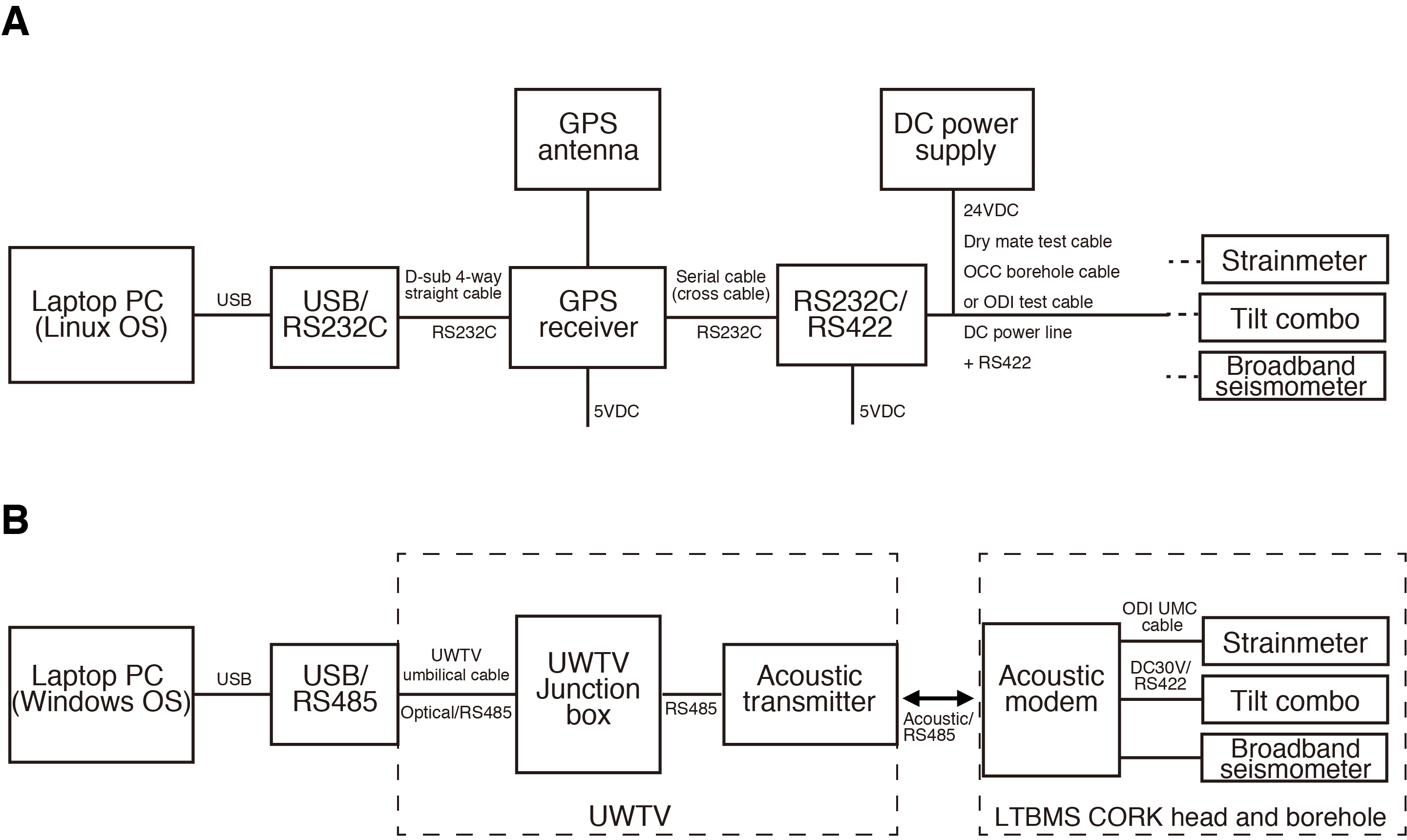
Figure F6. LTBMS sensor health check connection.
Table T3 contains a comprehensive list of troubleshooting events during sensor and instrument carrier running, sensor cable testing, and attachment.
LTBMS assembly
Attaching miniscreens to 3.5 inch LTBMS backbone tubing
The three miniscreens were attached to ¼ inch Swagelok hydraulic tubing and to the lowermost portion of the 3.5 inch LTBMS tubing with stainless steel banding. They were protected by two metal centralizers.
Strainmeter testing and attachment
After the 3.5 inch LTBMS tubing with bullnose, miniscreens, and cement port was run into the drilling floor, strainmeter preparations began with a full function test. See CHECKLISTS in Supplementary material [Becker et al., 2018] for the function test check sheets. Several issues were encountered during the first strainmeter test, including problems with the laptop PC screen displays and a communication disruption between the strainmeter and laptop PC caused by a damaged testing cable (see Table T3).
When the test was completed, the strainmeter with a crossover joint attached on the bottom end (for permanent connection to the LTBMS) and top end (used only for lifting the strainmeter for deployment), was loaded onto the riser transport system (RTS) and picked up on the rig floor to attach it to the 3.5 inch LTBMS tubing and ¼ inch hydraulic tubing. (Figure F7).
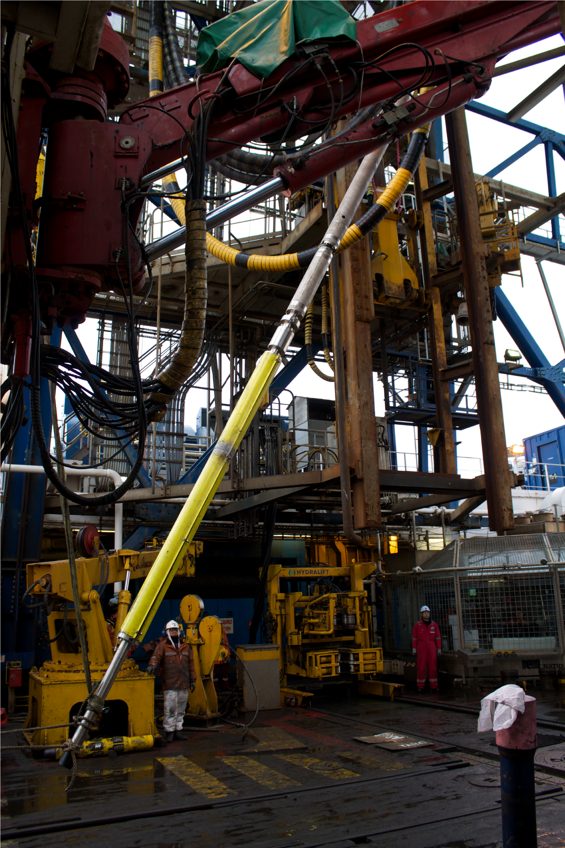
Figure F7. Strainmeter.
Attaching the instrument carrier
With the strainmeter attached to the 3.5 inch LTBMS tubing, the instrument carrier was loaded onto the RTS. The temporary crossover joint, which connected the top of strainmeter to the HPS, was removed to connect the top of the strainmeter to the bottom of the instrument carrier (Figure F8). Before attachment, the condition of the O-ring between the strainmeter and the instrument carrier was checked (Figure F9).
Figure F8. Strainmeter crossover connection.
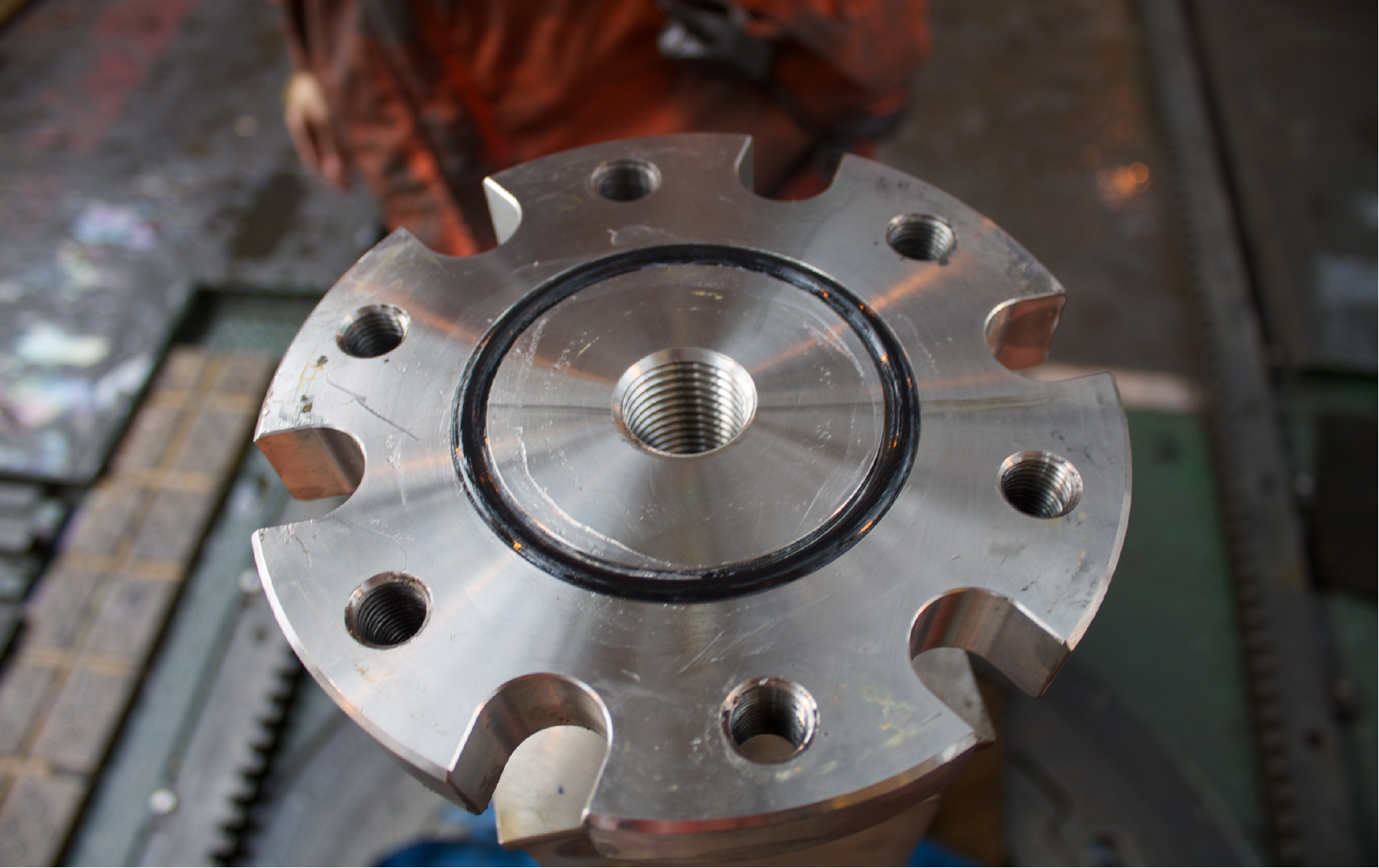
Figure F9. Crossover O-ring.
The two hydraulic tubes that pass through the strainmeter and extend to the miniscreens and the bottom of the strainmeter were not properly labeled. Therefore, it was very hard to distinguish between the tubing that led to the miniscreens and the tubing that led to the strainmeter. A water-pump test confirmed which hydraulic tube was which, and the correct hydraulic connections were made.
Full instrument Test 1
Before the strainmeter and instrument carrier were lowered into the water, a full test (Test 2 in Table T3) for all instruments was performed through dry-mateable connections (DMCs). The results show that all instruments were functioning well; however, several issues occurred during the test:
- One of the five wire connections of the USB-RS422 Moxa adaptor on the test cable was loose, causing communication problems during the broadband seismometer test. We solved this problem by tightening the wire connection.
- The voltage of the original power supply from the broadband seismometer-stream server (the “black box”) was not high enough, likely because of the long length of the sensor cables. We solved this problem by directly supplying power through an external power connector.
- Both PCs used for the test showed delayed response in automatically adjusting their screen brightness, initially causing difficulties in reading the screen outputs. To deal with this issue, we prepared another (the third) PC as an extra spare.
All of these problems led to delays in finishing this test, but the lessons learned helped us to improve the management of our testing equipment. Overall, later tests went much more smoothly.
Attaching the sensor cables and flatpack
When the instrument carrier, strainmeter, and lower tubing section were lowered into the moonpool, the sensor cables and hydraulic flatpack were connected by Center for Deep Earth Exploration (CDEX) engineers and Mantle Quest Japan (MQJ) crew. The flatpack and sensor cables were attached to the 3.5 inch LTBMS tubing using both plastic zip-ties and SUS stainless steel banding (Figure F10). Metal centralizers were spaced at 2.3 m (for open hole) and 4.5 m intervals (for inside of casing) along the tubing joints to protect the sensor cables and flatpack. Aside from a brief crossing of sensor lines while lowering the casing, no major issues occurred.
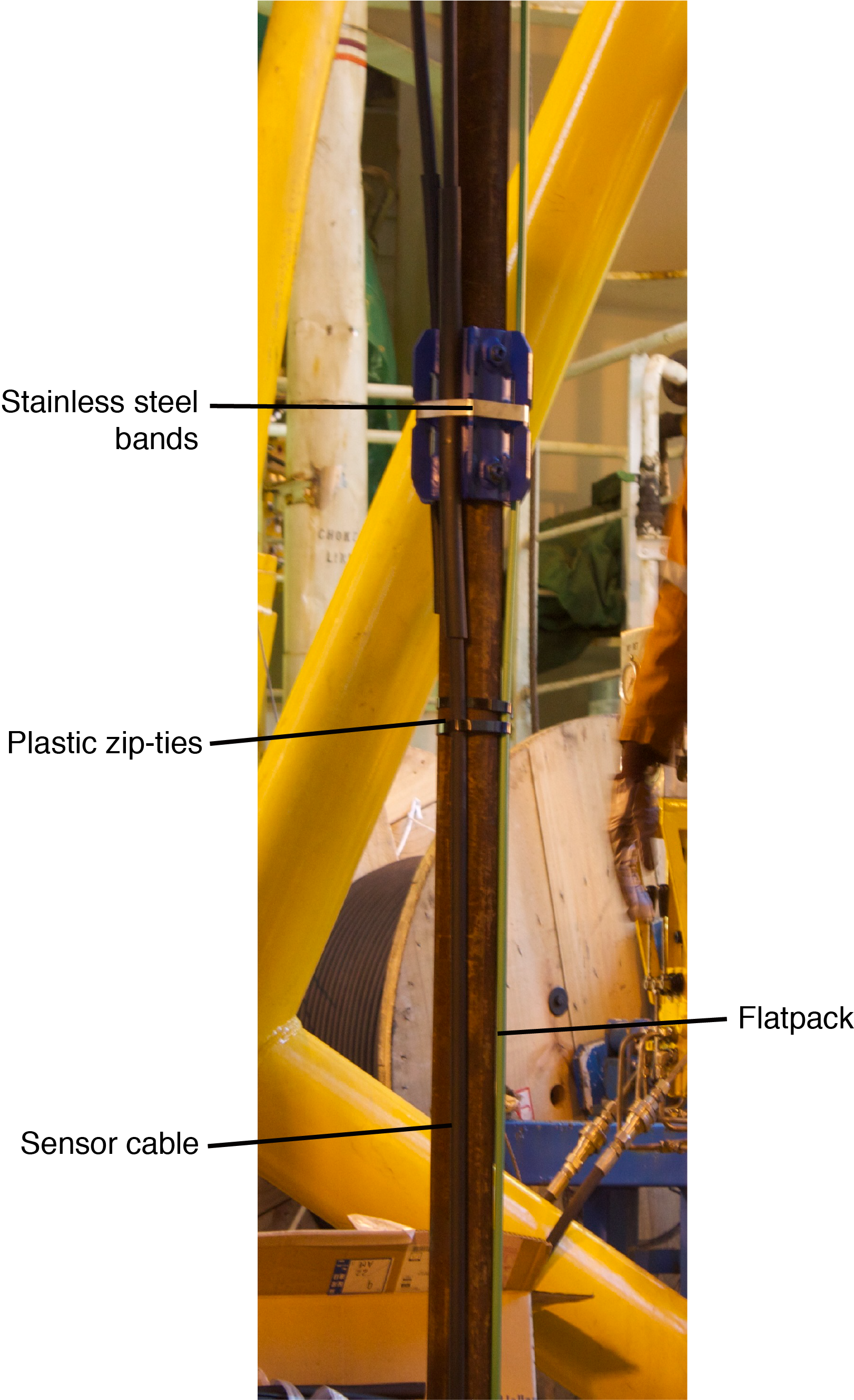
Figure F10. Cables and flatpack.
While the instrument carrier was progressively lowered into the water by adding 3.5 inch LTBMS tubing joints one by one, the flatpack and sensor cables continued to be attached to the tubing using plastic zip-ties and stainless steel bands. The sensor cables and flatpack were strung up for attachment through cable drums and pulleys set up the moonpool area (Figure F5).
Attaching swellable packer, passing sensors cables through the swellable packer, and sensor communication tests
The swellable packer was attached to the 3.5 inch LTBMS tubing at a position that would correspond to 68 mbsf once deployed downhole in Hole C0006G. A Halliburton engineer inserted the sensor cables and flatpack through the swellable packer (Figure F11). Before passing the sensor cables through the swellable packer, a simple test was performed for all instruments through DMCs.
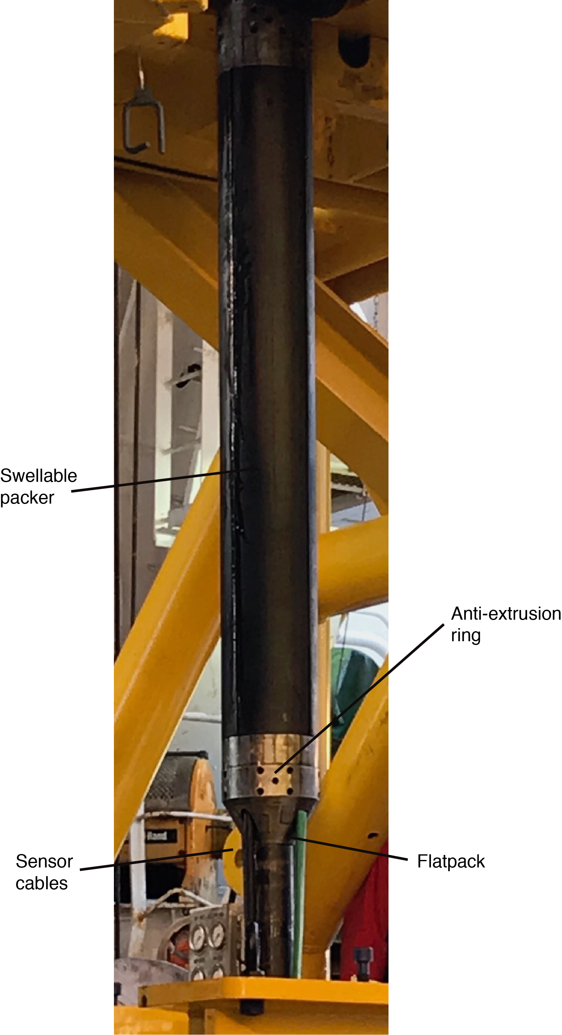
Figure F11. Swellable packer.
Full instrument Test 2
Immediately after passing the sensor cables through the swellable packer, a full test was performed for all instruments through DMCs. The test results confirmed that communication to all sensors was not affected by running the sensor cables through the swellable packer.
Attaching the LTBMS CORK head
After all instruments and the swellable packer were assembled and lowered, the LTBMS CORK head was connected to the HART while still on the RTS and then raised above the drill floor and attached to the 3.5 inch LTBMS tubing. The sensor cables and hydraulic flatpack were passed through the LTBMS CORK head’s hanger. The sensor cables were temporarily attached to the LTBMS CORK head with plastic zip-ties, and the hydraulic flatpack was terminated and attached to the PSU hydraulic tubing, completing the pressure sensing system. No issues occurred during LTBMS CORK head attachment. A full test was performed before cutting the sensor cables.
Cutting sensor cables and full instrument Test 3: termination of sensor cables
After the LTBMS CORK head was lowered to just above the moonpool and the attachment of sensor cables to the 3.5 inch LTBMS tubing was completed, the sensor cables were cut, leaving ~10 m of extra length for termination. Four UMCs were prepared for the terminated cables (one as a spare).
Immediately after cutting the sensor cables, a full test was performed for all instruments through direct connections of DMCs and the cut wires in each of the three sensor cables. All instruments were fully functional.
Attaching UMCs and instrument tests
Teledyne ODI engineers prepared the UMCs for the termination of each of the three sensor cables at a workstation located in the moonpool area. During this process, a series of instrument tests were conducted. A test was conducted after the Teledyne ODI engineers had soldered the wires, and another test was conducted after the engineers completed the final epoxy (resin) pour during UMC construction. The first of these two tests was performed as a full function test, including a broadband seismometer test confirming downlink function. However, the second test after the epoxy had hardened was not a full function test; the downlink function check procedures were skipped. The broadband seismometer test procedure was revised to include a downlink function check for all following tests. When the communication cables were spliced midway through UMC termination, a third full instrument test was performed. All instruments were functioning properly, and the Teledyne ODI engineers completed the UMC terminations. A fourth full test was performed through direct connection to the newly fabricated UMCs, and again all instruments proved fully functional.
Attaching UMCs and cables to the LTBMS CORK head and further testing
With the UMCs and instruments fully functional, the cables and UMCs were then attached to the LTBMS CORK head with plastic zip-ties. Once they were fully attached (Figure F12), a full function test of all instruments (including the PSU) was performed through direct connection to the UMCs. A major issue was found when the downlink connection to the broadband seismometer ceased functioning. The cause was isolated to a damaged communication cable, more specifically in the newly built UMC pressure housing. A full function test, including the downlink function, had not been conducted after epoxy hardened nor after carrying the UMCs to the LTBMS CORK head (see CHECKLISTS in Supplementary material [Becker et al., 2018]). The broadband seismometer cable was removed from the LTBMS CORK head and cut just beneath the UMC pressure housing. Communication with the sensor was checked through direct connection between the borehole cable and test equipment. The results confirmed that the broadband seismometer itself was functional, isolating the problem to a damaged communication cable, more specifically in the newly built UMC pressure housing. The Teledyne ODI engineers prepared a new UMC pressure housing (using a spare).
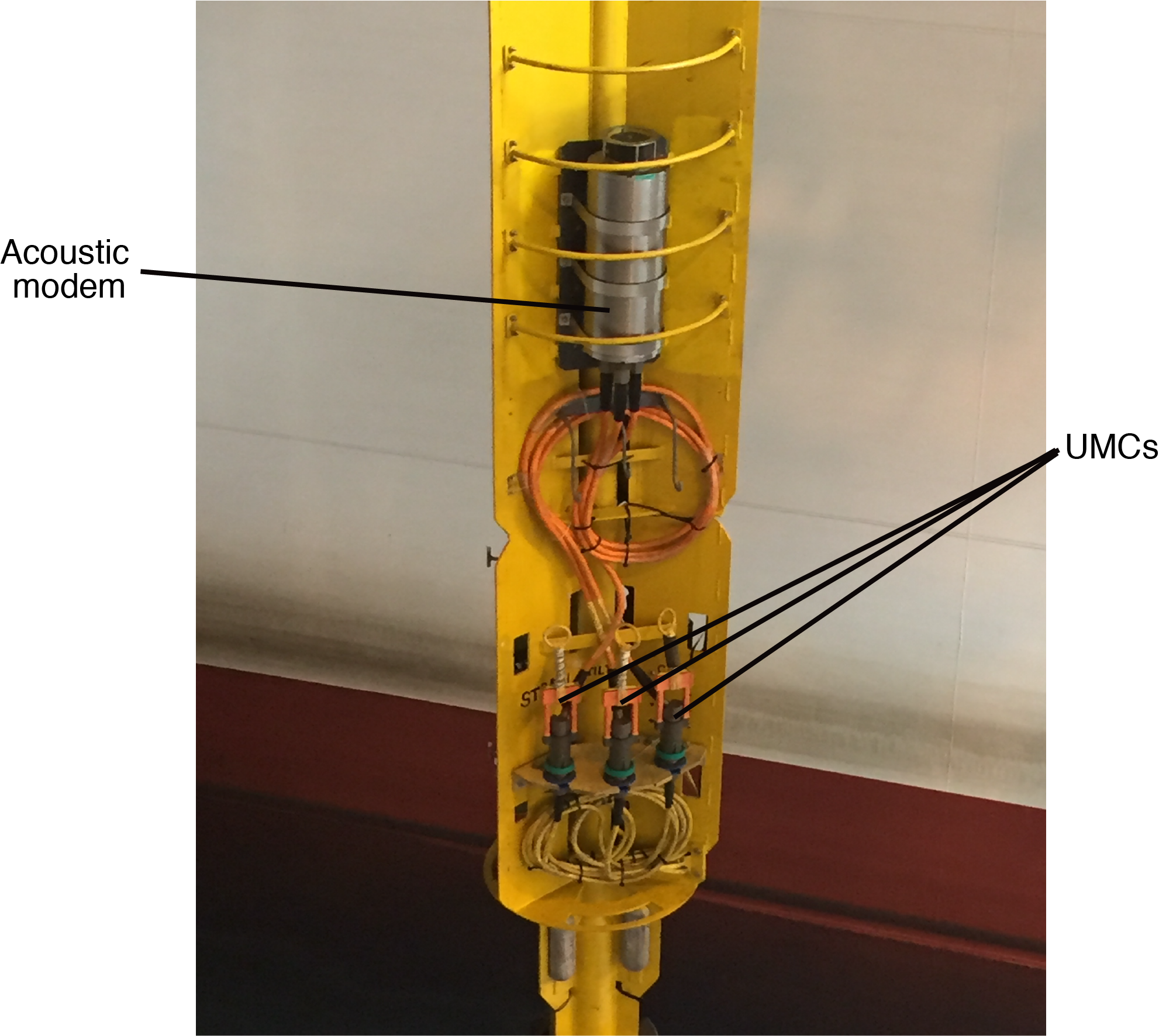
Figure F12. Acoustic modem and UMC cables.
Similar instrument tests, including a downlink function test, were performed again for the seismometer during the new UMC construction: one test each after electrical connection (soldering), epoxy hardening, and completion, with each test proving successful. Upon reattaching the UMC and seismometer cable, one final full test was performed through direct connection to all instruments, and all were functioning properly.
Acoustic modem instrument testing and final LTBMS CORK head preparation
All instruments were then connected to the acoustic modem through UMCs (Figure F12). Once connected, a full test at the moonpool was performed through the modem, which ensured instrument functionality with the acoustic communication system (see Test 18 in Instrument_tests.xlsx in CHECKLISTS in Supplementary material [Becker et al., 2018]). Upon completing the test successfully, the formation and sampling valves were opened to the ocean (hydrostatic pressure) and the LTBMS CORK head was lowered into the water for 5 min to flush the hydraulic tubing with seawater. The LTBMS CORK head was raised, the valves for Pressure Ports 1 and 3 were closed (see Figure F3 in the Expedition 380 methods chapter [Kinoshita et al., 2018]), and the Activation Kit was then attached to the LTBMS. All valves were zip-tied to ensure the handles did not turn during descent.
Lowering the LTBMS
Acoustic modem instrument testing at 1400 and 3880 m BRT
During descent, two more acoustic modem tests were performed through the UWTV, one when the instrument carrier reached 1400 m BRT and one when it reached 3880 m BRT. Each test showed that all instruments were functioning properly. After the LTBMS CORK head and UWTV were deployed, Connection B (Figure F6) was used for a series of health checks through acoustic communication. The acoustic transmitter and the acoustic modem have internal batteries in their pressure housings and can supply DC power to their internal circuits and to the borehole sensors.
Reentry and landing
Acoustic modem testing after reentry and landing
Prior to reentry, a cement circulation test was performed to inspect the cement tubing in the instrument carrier. A small leak at the connection between the instrument carrier and the strainmeter was detected. This leakage may have been caused by a weak or cracked welding point, and the science team confirmed that the leak would not negatively affect the cementation process. The LTBMS reentered, and the LTBMS CORK head landed smoothly. A full acoustic modem test was performed after landing to ensure that the instruments remained healthy.
Cementing
Checking instruments during cementing and final acoustic modem test
Once the landing of the LTBMS CORK head was completed, the cementing process started. The process was completed without any problems. Brief instrument checks were performed through the acoustic modem every 30 min to ensure functionality during cementing. After cementing, the final full acoustic modem test was performed (see Test 23 in Instrument_tests.xlsx in CHECKLISTS in Supplementary material [Becker et al., 2018]). Test results suggested that the lowermost thermistor (T1) had stopped recording. After connection to DONET, that sensor seemed to be working properly. The strainmeter contains a temperature sensor that could substitute for a potential loss of the T1 thermistor sensor.
Releasing the LTBMS
After cementing was completed, the UWTV acoustic modem triggered the Activation Kit to release the HART. Although pressure was released (confirmed by the UWTV camera and by checking the gauges on the Activation Kit), the HART did not release. The UWTV was moved up and down past the Activation Kit to trigger the manual release to no effect. Multiple runs with the UWTV also had no apparent effect. The UWTV was recovered to modify the guide funnel by adding 5 mm rubber sheets and welding 12 mm of metal banding to the inside half of the guide funnel door to reduce the inside diameter of the funnel and make better contact with the manual trigger pins on the outside of the Activation Kit. This strategy was finally successful. Upon detaching the HART, the separation was visually confirmed before running one final sensor test with the UWTV acoustic modem.
References
Becker, K., Kinoshita, M., Toczko, S., and the Expedition 380 Scientists, 2018. Supplementary material, https://doi.org/10.14379/iodp.proc.380supp.2018. Supplement toBecker, K., Kinoshita, M., Toczko, S., and the Expedition 380 Scientists, NanTroSEIZE Stage 3: Frontal Thrust Long-Term Borehole Monitoring System (LTBMS).Proceedings of the International Ocean Discovery Program, 380: College Station, TX (International Ocean Discovery Program). https://doi.org/10.14379/iodp.proc.380.2018
Expedition 314 Scientists, 2009. Expedition 314 Site C0006. InKinoshita, M., Tobin, H., Ashi, J., Kimura, G., Lallemant, S., Screaton, E.J., Curewitz, D., Masago, H., Moe, K.T., and the Expedition 314/315/316 Scientists, Proceedings of the Integrated Ocean Drilling Program,314/315/316: Washington, DC (Integrated Ocean Drilling Program Management International, Inc.). https://doi.org/10.2204/iodp.proc.314315316.118.2009
Expedition 316 Scientists, 2009. Expedition 316 Site C0006. In Kinoshita, M., Tobin, H., Ashi, J., Kimura, G., Lallemant, S., Screaton, E.J., Curewitz, D., Masago, H., Moe, K.T., and the Expedition 314/315/316 Scientists, Proceedings of the Integrated Ocean Drilling Program,314/315/316: Washington, DC (Integrated Ocean Drilling Program Management International, Inc.). https://doi.org/10.2204/iodp.proc.314315316.134.2009
Expedition 332 Scientists, 2011. Expedition 332 summary. InKopf, A., Araki, E., Toczko, S., and the Expedition 332 Scientists, Proceedings of the Integrated Ocean Drilling Program, 332: Tokyo (Integrated Ocean Drilling Program Management International, Inc.). https://doi.org/10.2204/iodp.proc.332.101.2011
Heki, K., 2007. Secular, transient, and seasonal crustal movements in Japan from a dense GPS array: implication for plate dynamics in convergent boundaries. InDixon, T.H., and Moore, J.C. (Eds.), The Seismogenic Zone of Subduction Thrust Faults:New York (Columbia University Press), 512–539.
Kinoshita, M., Becker, K., Toczko, S., Edginton, J., Kimura, T., Machida, Y., Roesner, A., Senyener, B., and Sun, T., 2018. Expedition 380 methods. InBecker, K., Kinoshita, M., Toczko, S., and the Expedition 380 Scientists, NanTroSEIZE Stage 3: Frontal Thrust Long-Term Borehole Monitoring System (LTBMS).Proceedings of the International Ocean Discovery Program, 380: College Station, TX (International Ocean Discovery Program). https://doi.org/10.14379/iodp.proc.380.102.2018
Kopf, A., Saffer, D., Toczko, S., Araki, E., Carr, S., Kimura, T., Kinoshita, C., Kobayashi, R., Machida, Y., Rösner, A., and Wallace. L.M., 2017. Expedition 365 summary. With contributions by S. Chiyonobu, K. Kanagawa, T. Kanamatsu, G. Kimura, and M.B. Underwood. InSaffer, D., Kopf, A., Toczko, S., and the Expedition 365 Scientists, NanTroSEIZE Stage 3: Shallow Megasplay Long-Term Borehole Monitoring System.Proceedings of the International Ocean Discovery Program, 365: College Station, TX (International Ocean Discovery Program). https://doi.org/10.14379/iodp.proc.365.101.2017
Miyazaki, S., and Heki, K., 2001. Crustal velocity field of southwest Japan: subduction and arc-arc collision. Journal of Geophysical Research: Solid Earth, 106(B3):4305–4326. https://doi.org/10.1029/2000JB900312
Moore, G.F., Park, J.-O., Bangs, N.L., Gulick, S.P., Tobin, H.J., Nakamura, Y., Sato, S., et al., 2009. Structural and seismic stratigraphic framework of the NanTroSEIZE Stage 1 transect. InKinoshita, M., Tobin, H., Ashi, J., Kimura, G., Lallemant, S., Screaton, E.J., Curewitz, D., Masago, H., Moe, K.T., and the Expedition 314/315/316 Scientists, Proceedings of the Integrated Ocean Drilling Program,314/315/316: Washington, DC (Integrated Ocean Drilling Program Management International, Inc.). https://doi.org/10.2204/iodp.proc.314315316.102.2009
Seno, T., Stein, S., and Gripp, A.E., 1993. A model for the motion of the Philippine Sea plate consistent with NUVEL-1 and geological data. Journal of Geophysical Research: Solid Earth, 98(B10):17941–17948. https://doi.org/10.1029/93JB00782
Strasser, M., Dugan, B., Kanagawa, K., Moore, G.F., Toczko, S., Maeda, L., Kido, Y., Moe, K.T., Sanada, Y., Esteban, L., Fabbri, O., Geersen, J., Hammerschmidt, S., Hayashi, H., Heirman, K., Hüpers, A., Jurado Rodriguez, M.J., Kameo, K., Kanamatsu, T., Kitajima, H., Masuda, H., Milliken, K., Mishra, R., Motoyama, I., Olcott, K., Oohashi, K., Pickering, K.T., Ramirez, S.G., Rashid, H., Sawyer, D., Schleicher, A., Shan, Y., Skarbek, R., Song, I., Takeshita, T., Toki, T., Tudge, J., Webb, S., Wilson, D.J., Wu, H.-Y., and Yamaguchi, A., 2014. Expedition 338 summary. InStrasser, M., Dugan, B., Kanagawa, K., Moore, G.F., Toczko, S., Maeda, L., and the Expedition 338 Scientists, Proceedings of the Integrated Ocean Drilling Program, 338: Yokohama, Japan (Integrated Ocean Drilling Program). https://doi.org/10.2204/iodp.proc.338.101.2014
1 Kinoshita, M., Becker, K., Toczko, S., Edgington, J., Kimura, T., Machida, Y., Roesner, A., Senyener, B., Sun, T., 2018. Site C0006. In Becker, K., Kinoshita, M., Toczko, S., and the Expedition 380 Scientists, NanTroSEIZE Stage 3: Frontal Thrust Long-Term Borehole Monitoring System (LTBMS). Proceedings of the International Ocean Discovery Program, 380: College Station, TX (International Ocean Discovery Program). https://doi.org/10.14379/iodp.proc.380.103.2018
2 Expedition 380 Scientists’ affiliations.
This work is distributed under the Creative Commons Attribution 4.0 International(CC BY 4.0) license. 
- F1. Site locations.
- F2. Interpreted seismic cross section and LTBMS site locations.
- F3. Interpreted seismic depth section.
- F4. Seismic section and logging and coring results.
- F5. Sensor cable and flatpack drum configuration.
- F6. LTBMS sensor health check connection.
- F7. Strainmeter.
- F8. Strainmeter crossover connection.
- F9. Crossover O-ring.
- F10. Cables and flatpack.
- F11. Swellable packer.
- F12. Acoustic modem and UMC cables.