Arculus, R.J., Ishizuka, O., Bogus, K., and the Expedition 351 Scientists
Proceedings of the International Ocean Discovery Program Volume 351
publications.iodp.org

https://doi.org/10.14379/iodp.proc.351.201.2017
Data report: sedimentary columns with facies and bedding for Units II–IV at IODP Site U14381
K. Johnson,2 R. Waldman,2 and K.M. Marsaglia2
Keywords: International Ocean Discovery Program, IODP, JOIDES Resolution, Expedition 351, Site U1438, Izu-Bonin-Mariana, Amami Sankaku Basin, Kyushu-Palau Ridge, stratigraphic columns
MS 351-201: Received 28 August 2016 · Accepted 19 July 2017 · Published 20 November 2017
Abstract
This report contains a database of detailed section-, core-, and hole-scaled stratigraphic columns constructed from shipboard and shore-based observations of core recovered during International Ocean Discovery Program (IODP) Expedition 351 at Site U1438. The section- and core-level stratigraphic columns include bedding and facies designations intended for use in postexpedition studies, including analyses of depositional processes and sediment provenance, as well as contexts for geochemical, isotopic, and geochronological analyses. We also present a stratigraphic synthesis column reflecting bedding and facies variation at the site.
Introduction
The Izu-Bonin-Mariana system was the focus of several International Ocean Discovery Program (IODP) expeditions (350, 351, and 352) in 2014 that were designed to answer questions about the fundamental plate tectonic processes of convergent-margin initiation and crustal development in intraoceanic settings (see the Expedition 351 summary chapter [Arculus et al., 2015b]). The primary objectives of Expedition 351 included discovering the nature and origin of the presubduction basement (lithosphere) in the Amami Sankaku Basin (Figure F1) west of the Kyushu-Palau Ridge (remnant arc) and the subsequent history of magmatic arc initiation and evolution as recorded in the overlying stratigraphic section. These objectives were achieved by drilling a single deep hole at Site U1438, where a thick 1.61 km volcanic/sedimentary section was cored (see the Expedition 351 summary chapter [Arculus et al., 2015b]). The Holocene to Eocene stratigraphy at Site U1438 was divided into five lithostratigraphic units (Figure F2): four sedimentary units (I, II, III, and IV) overlying volcanic rocks designated as igneous Unit 1 (1461.1–1611.1 meters below seafloor [mbsf]). Sedimentary Unit I (0–160.3 mbsf) comprises mainly hemipelagic mud with minor ash beds, whereas sedimentary Units II (160.3–309.6 mbsf), III (309.6–1361.4 mbsf), and IV (1361.4–1461.1 mbsf) are dominated by coarser (sand–gravel) marine volcaniclastic sediments. Sediment accumulation rates are estimated as having decreased from ~120 m/My in Units II and III (Eocene to Oligocene) to ~5 m/My in Unit I (Miocene to Holocene) (see the Site U1438 chapter [Arculus et al., 2015c]).
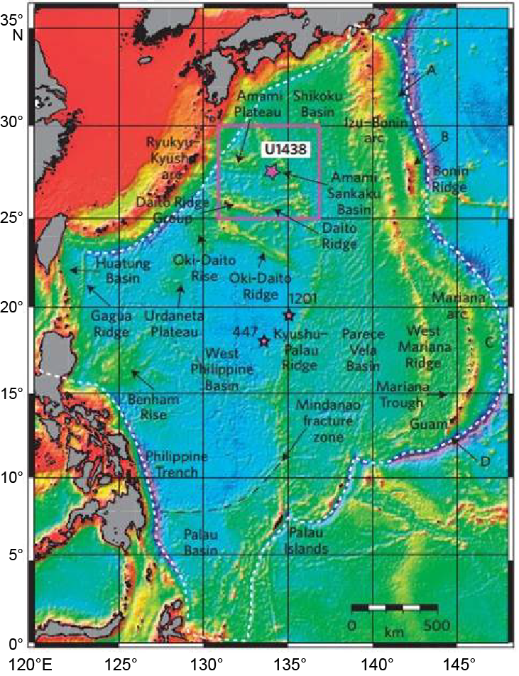
Figure F1. Location map, Site U1438.
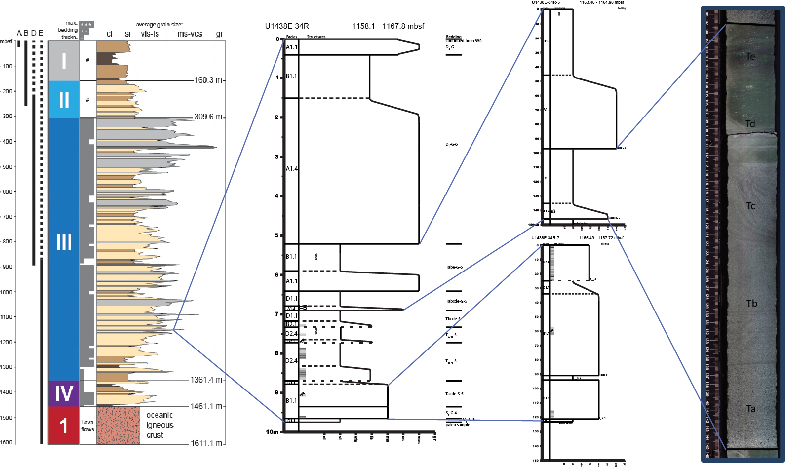
Figure F2. Relationships of hole summary, core, and section columns.
Shipboard scientists described ~1.15 km of volcaniclastic sedimentary core recovered in the 1.46 km cored interval at Site U1438, logging changes in grain size, texture, color, and gross lithology, as well as the nature of bedding contacts and presence of sedimentary structures on a core-by-core basis. All of this information was recorded on 11 inch × 17 inch data sheets with high-resolution core images and then entered into the DESClogik database. These data were used to define the four lithostratigraphic units (I, II, III and IV) in combination with color, magnetic susceptibility, and gamma ray measurements. For the site report, DESClogik data were extracted to create figures showing gross downhole trends in grain size, presence of sedimentary structures, and bioturbation.
Units II, III, and IV comprise tuffaceous mudstone, sandstone, and breccia-conglomerate (see the Site U1438 chapter [Arculus et al., 2015c]). The sand includes mineral grains of plagioclase feldspar, ferromagnesian silicates, and opaque minerals, as well as a variety of vitric to holocrystalline and variably vesiculated volcanic lithic clasts. Gravel clasts include pumice, scoria, lava, and a variety of volcanic rock fragments. These sedimentary rocks are variably altered with common clay mineral and zeolite cements at depth.
There was no shipboard facies analysis or intercore integration (e.g., beds extending across core boundaries, patterns in bedding types, trends in grain size, etc.). This report provides stratigraphic columns with bedding and facies designations meant to be used in postexpedition studies, including analyses of depositional processes and sediment provenance, as well as contexts for geochemical, isotopic, and geochronological analyses. We also present a stratigraphic synthesis column reflecting bedding and facies variation at the site.
Methods
Illustrated stratigraphic columns were produced from the Unit II–IV cores recovered at Site U1438, first at the section level and then at the core level (Figure F2), starting from igneous basement (Core 351-U1438B-69R) and working upsection. Thicker beds present at the top of Unit III and structurally complex intervals at the Unit II/III boundary made the shorter section columns less informative, so starting at Core 351-U1438D-48R (~660 mbsf) and continuing uphole through Core 351-U1438B-18H, only summaries at the core level were produced.
These stratigraphic columns at the section and core levels were constructed based on slabbed core images taken shipboard, data in the DESClogik database exported into a Microsoft Excel spreadsheet and summarized on visual core description sheets, and shipboard notes taken by K. Marsaglia during periods when multiple cores were laid out for visual inspection during several shipboard “sampling parties.” Additional textural information at discrete intervals was gleaned from petrographic examination of a suite of 241 thin sections produced from shipboard samples of mainly sandy lithologies with some mudstone facies from Unit IV. Adobe Illustrator was used to combine these data into an easy-to-read page format at the section and core levels.
On each page, the illustrated width of the core interval (horizontal scale) represents grain size within the core. Intervals are marked with symbols for bedding contacts and sedimentary and tectonic structures as defined in Figure F3, using a system modeled after Expedition 351 shipboard descriptions (see the Expedition 351 methods chapter [Arculus et al., 2015a]). Two classification schemes were applied to the core: one broad (facies) and the other more detailed (bedding/depositional units). Facies divisions and bed-scale intervals were often bounded by bedding planes, but in some instances, boundary relationships were masked by diagenetic overprinting, drilling deformation, and/or gaps in recovery. A column on the left of each diagram includes facies classifications, whereas bedding classifications are indicated on the right at the bottom of individual beds or intervals of lamination distinguished as bedding <1 cm.
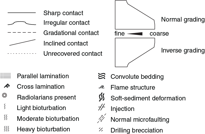
Figure F3. Symbols used in constructing stratigraphic columns, Site U1438.
Facies classification
Sequences of beds in the core as portrayed on the stratigraphic columns were first classified into a number of facies categories (Table T1). The deep-water sediment classification scheme used by Pickering et al. (1986) and Pickering and Hiscott (2015) was used in its original form, with additional classes observed in Site U1438 cores such as debrites and tuffs. Classes are designated by prefixes associated with grain size (Pickering et al., 1986):
- A = gravels and pebbly sand classes.
- B = sand classes.
- C = sand and mud couplet classes.
- D = silt classes.
- E = mud and clay classes.
Table T1. Facies classification scheme. Download table in .csv format.
Following the prefix is a two-part number code. The first number represents bed organization:
Next, after a decimal point, is a second number that has different meanings for each prefix.
Bedding/depositional classification
Site U1438 core contains several bedding types associated with gravity flow or pyroclastic processes (Figure F4). Grain size variations and sedimentary structures were the main criteria used to help differentiate which type of depositional mechanism (turbidity current, debris flow, or pyroclastic fall/flow) to which each bed-scale interval belonged. Once the broad bedding category was determined (e.g., turbidite, debris flow, or tuff), more specific classification schemes were applied. For example, three turbidite classification options were used, each associated with different grain size distributions reflecting different flow densities.
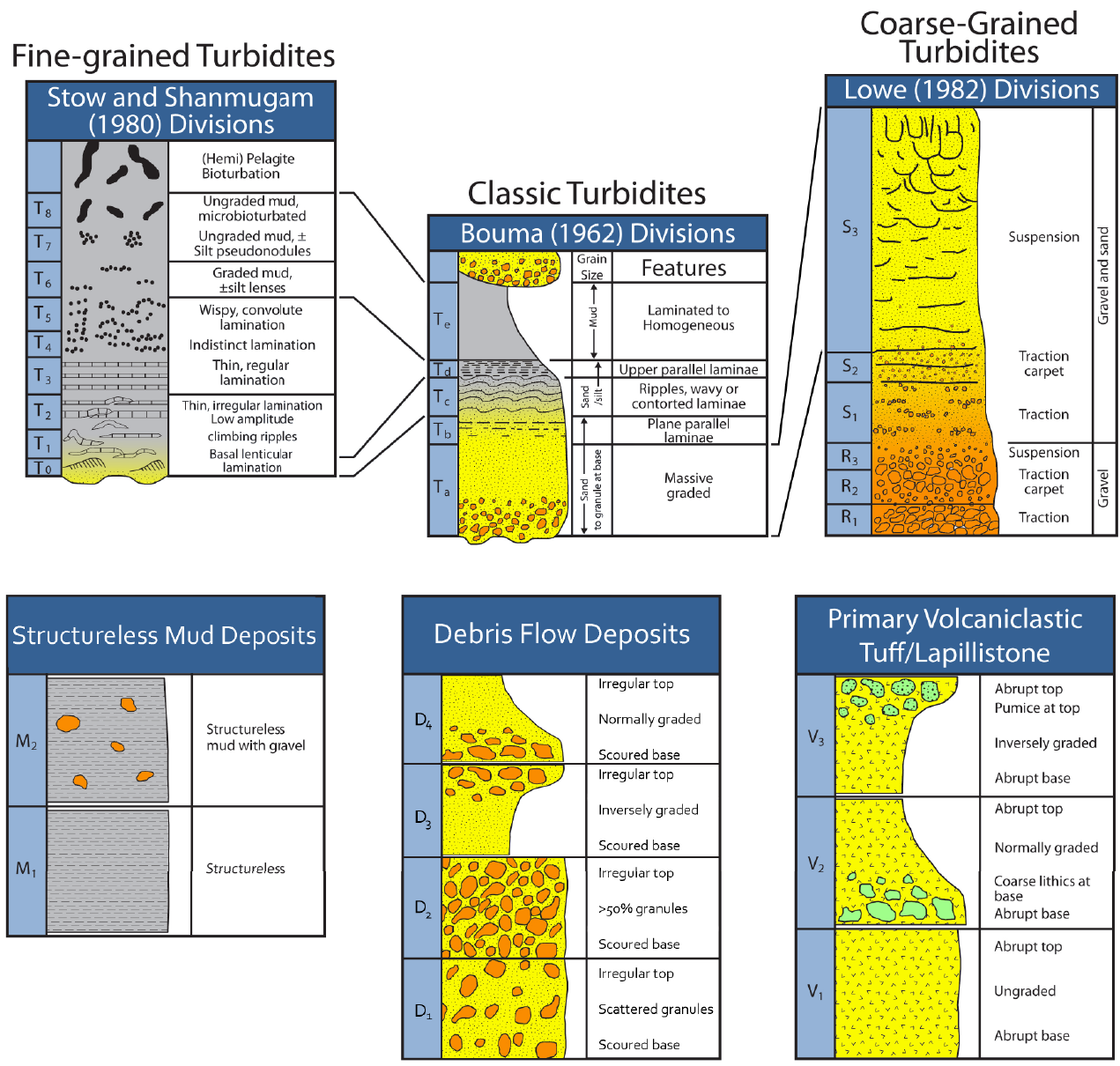
Figure F4. Classification schemes used in this study.
Medium-grained turbidites
Medium-grained turbidites (classic turbidites) were classified using the Bouma sequence divisions (Bouma, 1962) (Figure F4) as a root with hyphenated supplements for maximum grain size and deposit thickness: T(Bouma divisions)-(maximum grain size)-(deposit thickness). The supplements, maximum grain size (mud, silt, sand, or gravel) and deposit thickness, are defined in Tables T2 and T3. For example, Tacde-G-5 refers to a deposit exhibiting Bouma divisions a, c, d, and e with a maximum grain size of granule and a thickness between 30 and 100 cm.
Table T2. Grain size designators. Download table in .csv format.
Table T3. Bed/deposit thickness designators. Download table in .csv format.
Fine-grained turbidites
Fine-grained turbidites, resulting from low-density turbidity currents, were classified according to Stow and Shanmugam (1980), who separate Bouma’s Tc, Td, and Te divisions into nine detailed subdivisions designated T0–T8 (Figure F4). The T0 division correlates to the Bouma Tc division, the T1–T5 divisions correlate to the Bouma Td division, and the T6–T8 divisions correlate to the Bouma Te division. The T0 division contains basal lenticular lamination. The T1–T5 divisions transition from well-developed convolute bedding, to irregular laminations and regular laminations, and then to indistinct laminations. The T6–T8 divisions transition from graded mud and silt, to ungraded mud and silt, and finally to ungraded and bioturbated mud. Above T8 in section is hemipelagic bioturbated sediment, which in this study is simply grouped with T8. The divisions are used in a similar way to those of the classic turbidites described above, where the divisions present are displayed (i.e., T3568) with hyphenated supplements for maximum grain size and deposit thickness (Tables T2, T3): T(divisions)-(maximum grain size)-(deposit thickness). For example, T3568-Si-3 refers to a deposit exhibiting T3, T5, T6, and T8 divisions, a maximum grain size of silt, and a total thickness between 5 and 10 cm. A complete sequence was very rarely observed; instead, partial sequences were more common, referred to as top-absent, base-absent, and middle-absent based on the absence of Te, Tc, or Td Bouma divisions, respectively, as defined by Pickering et al. (1986).
Coarse-grained turbidites
Coarse-grained turbidites, resulting from high-density turbidity currents, were classified using the Lowe (1982) “S” or “R” prefixes and divisions (Figure F4). The Bouma Ta division is generally equivalent to Lowe division “S3.” Lowe division S is defined as follows:
- S3 = massive, graded, and suspension-sourced gravel and sand division with dish structures.
- S2 = gravel and sand oriented as a traction carpet.
- S1 = also a result of traction but has more organized coarse grains.
Below S3–S1 is a sequence of gravel-sized divisions, labeled R3–R1, that are rarely in sequence with S3–S1 due to movement of the flow-dispersing gravel-sized clasts more proximally than sand-sized grains. R3–R1 are described similar to S3–S1 but lack sandy matrix and have larger gravel clasts. In this study, coarse-grained turbidites were classified similarly to classic turbidites but using the Lowe divisions instead of Bouma division: S/R(Lowe divisions)-(maximum grain size)-(deposit thickness). For example, S12-G-6 is a coarse-grained turbidite sequence with Lowe divisions S1 and S2, a maximum grain size of gravel, and a total thickness <100 cm.
Debris flow deposits
Debris flow deposits were classified based on criteria outlined in Boggs (2011), which describes four varieties of debris flows that contain clasts supported by a finer-grained matrix (Figure F4). The scheme developed for this study uses a prefix of “D” followed by a subscripted number denoting characteristics:
- D1 = debris flow that is primarily sand with sparse floating gravel clasts.
- D2 = flows that have more gravel than sand but are not necessarily clast supported.
- D3 = inversely graded debrites.
- D4 = normally graded tops of debris flows.
Following the prefix are the two supplements, maximum grain size and bed thickness (Tables T2, T3): D(1, 2, 3, or 4)-(maximum grain size)-(bed thickness). For example, D2-G-4 is an unorganized gravel-rich debris flow deposit with a thickness between 10 and 30 cm. Note that the proportion of mud in these deposits was very hard to visually estimate by shipboard scientists and in core images owing to postdepositional alteration of volcanic components and cementation.
Mud/mudstone beds
Mud/mudstone beds were classified using a prefix of “M” followed by a subscripted number that represents bedding characteristics (Figure F4):
Following the prefix are the two supplements, maximum grain size and bed thickness (Tables T2, T3): M(1 or 2)-(maximum grain size)-(bed thickness). For example, M2-G-5 is a bed, 30–100 cm thick, that consists of structureless mud with gravel-sized clasts. Note that the M2 bed designation may be considered a mud flow deposit with an emplacement mechanism more similar to the D units described above. In addition, the structureless M1 beds may be a product of thorough bioturbation.
Tuff/Lapillistone
Tuff/Lapillistone was classified using the prefix “V” with an added subscripted number that corresponds to grading (Figure F4):
Akin to the previous schemes, two suffixes are added based on maximum grain size and bed thickness (Tables T2, T3) (e.g., V[1, 2, or 3 for grading]-[maximum grain size]-[bed thickness]). For example, V1-Si-4 refers to a tuffaceous bed/interval that is ungraded, has a maximum grain size of silt, and has a thickness of 10–30 cm.
Hole overlap
Lastly, a large-scale stratigraphic column with bedding and lithology variation was constructed from the core descriptions. In producing a generalized stratigraphic section, overlap in cored sections between holes was handled as follows. Shipboard correlation (figure F19 in Arculus et al. [2015d]) showed that the deformed Unit II–III contact zone was better recovered in Hole U1438B using extended core barrel drilling techniques than in Hole U1438D using rotary drilling techniques. Based on the correlation and depths, we used the larger scale stratigraphic sections from Cores 351-U1438B-1X through 30X to a depth of 257.13 mbsf then passed down to into Core 351-U1438D-7R starting at 257.60 mbsf, skipping Cores 1R through 6R, which averaged <30% recovery. The overlap of recovery in Unit III moving from Hole U1438D to U1438E was handled by using core recovered down through Core 351-U1438D-72R through 895.09 mbsf, and then starting at Core 351-U1438E-7R at 896.2 mbsf, within a thick conglomeratic interval present in each hole.
Results
Stratigraphic columns
Section columns, 538 in total ranging up to 150 cm in length, were constructed (see Appendix A). In constructing columns, recognizing bedding planes was problematic in some intervals owing to unrecovered contacts and breaks in cores as described in Methods. Several intervals were significantly altered, which also impeded column construction. The section columns for each core were combined into core summary columns (147 total) (see Appendix B). Thirteen Unit IV core summary columns were included here for completeness. No detailed columns were constructed for lithostratigraphic Unit I, as it consisted mainly of hemipelagic mud.
Grain sizes of individual beds were described in the DESClogik database. Thin section observations made in this study were consistent with shipboard analyses of thin sections, which indicated that the sand- to gravel-sized sediment was volcaniclastic in origin. As individual stratigraphic columns were finished, facies classes introduced by Pickering et al. (1986) were applied to the appearance of beds. A simplification was made to better apply to the interpretation of depositional processes in this study. This simplification disregarded specific differences in grading (taken into account by depositional unit classification), and internal structures (taken into account by symbols [Figure F3]). Once depositional unit classification schemes were determined (Figure F4), they were applied to groups of beds using structures, contacts, and lithologies identified within the core images. A few beds and groups of beds did not fit into any scheme and were left out of interpretations. Beds were often too disturbed (by drilling and/or soft-sediment deformation) to confidently determine deposit type; these were classified as having “disrupted bedding.”
Downhole distributions
To better illustrate downhole trends in these cores, several summary columns were constructed (Figure F5). The grain size distribution for each core was created by tabulating the total length of recovered core comprising each lithology. These data are presented in Table T4. These proportions were plotted on a 100% stacked plot to visualize distributions. The dominant grain size for each bed was used rather than the largest grain size, which was used in the depositional unit classification scheme. Within Unit IV and between 1460 and 1200 mbsf within Unit III, mud and sand are the dominant grain sizes. Abruptly starting at 1200 mbsf, silt and gravel dominate with lower sand contents and diminished mud content. Above, mud and sand again dominate in Unit II.
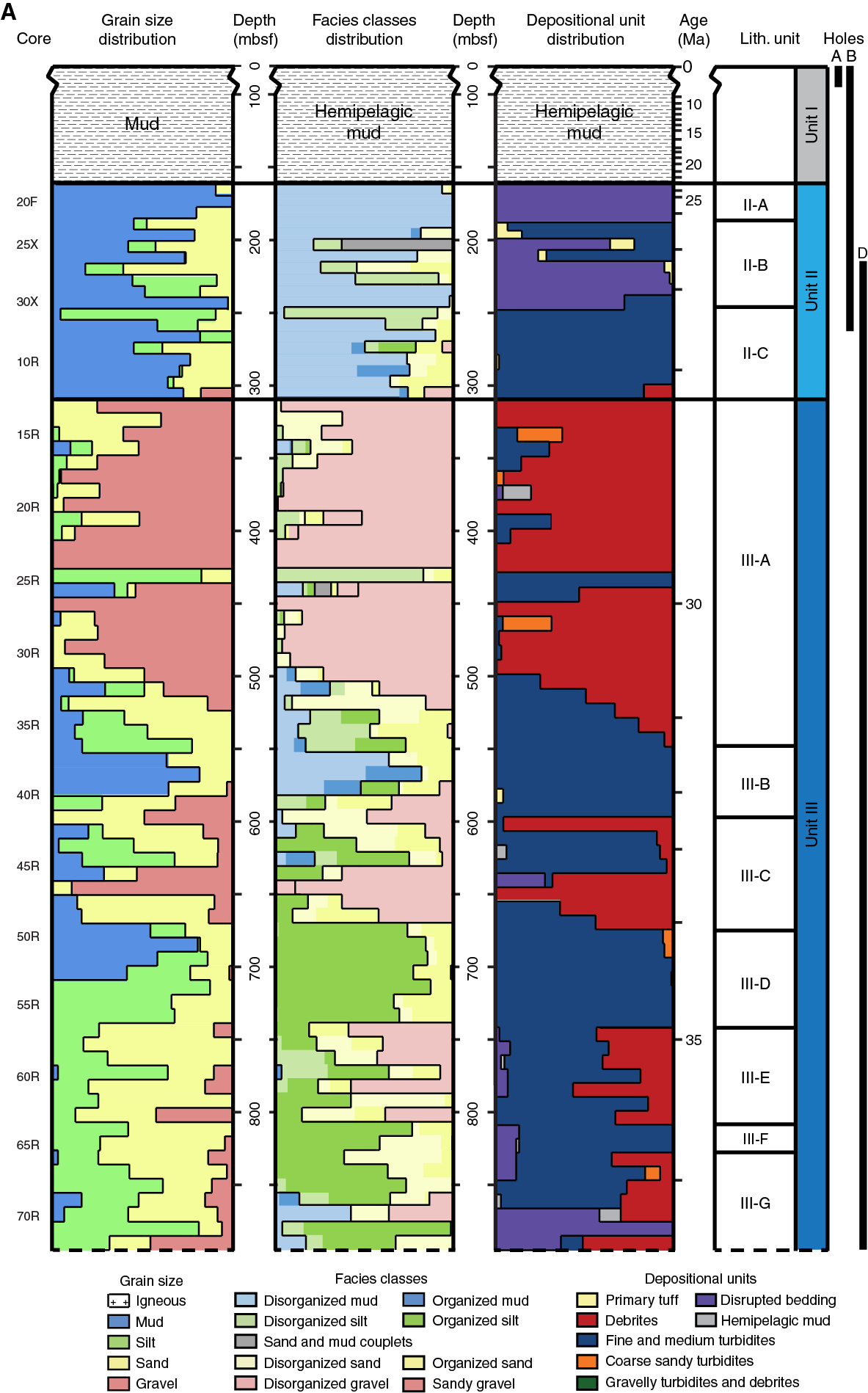
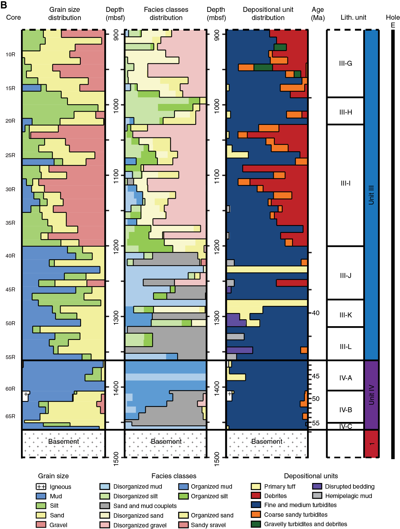
Figure F5. Distributions of grain size, facies classes, and depositional units.
Table T4. Lithologies on a core-to-core basis. Available in TRENDS in Supplementary material.
To formulate a facies class distribution plot (Figure F5), elements of each facies class (A, B, C, D, and E) listed in Table T1 were grouped as disorganized or organized. Details can be found in the Figure F6 caption. The total thickness representing each class present in each core summary column was tabulated and recalculated to 100%; the plot for each core’s distribution was then stacked to visualize their distribution in the section. Data are presented in Table T5. In Unit IV and below 1200 mbsf in Unit III, facies Classes C (organized sand and mud couplets) and E (mud) dominate, with organized mud more common below 1300 mbsf. This is the only interval where facies Class C is notable. The lowest half of this interval is rich in facies Class E2.1 (laminated mud), whereas the top has significant facies Class E1.1 (structureless mud). Above 1200 mbsf, facies Classes D (silt), B (sand), and A (gravel) are dominant, and Class A yields to Class D in fine intervals. From ~575 to 500 mbsf, a high proportion of facies Class E is again present before the facies Class A–dominated interval that precedes the Unit III/II boundary. Within Unit II, facies Classes E (mud) and B (sand) dominate with varying amounts of facies Class D (silt).

Figure F6. M1 hemipelagic mudstone, D2 debrite, and V1 primary tuff.
Table T5. Facies classes on a core-to-core basis. Available in TRENDS in Supplementary material.
Proportions of depositional unit types were tabulated on a core-by-core basis and plotted on a 100% stacked plot for visualization (Figure F5). Depositional unit data at a one-depositional-unit bin size for Unit III are visualized in Figure F7. Data are presented in Table T6. In Unit IV and below 1200 mbsf in Unit III, turbidites are dominant. Exceptions are tuff intervals within Cores 351-U1438E-47R and 42R. Above 1200 mbsf, debrites and coarse-grained turbidites are introduced and vary in proportion until the Unit III/II boundary. Intervals of solely turbidites exist within intervals that contain debrites. Unit II contains turbidites that progressively yield to tuff and hemipelagic mudstone upsection. Overall percentages of each type are as follows: ~57% turbidites (fine and medium grained), ~31% debrites, ~3% coarse-grained turbidites, ~2% tuff/lapillistone, and ~1% structureless mud deposits.
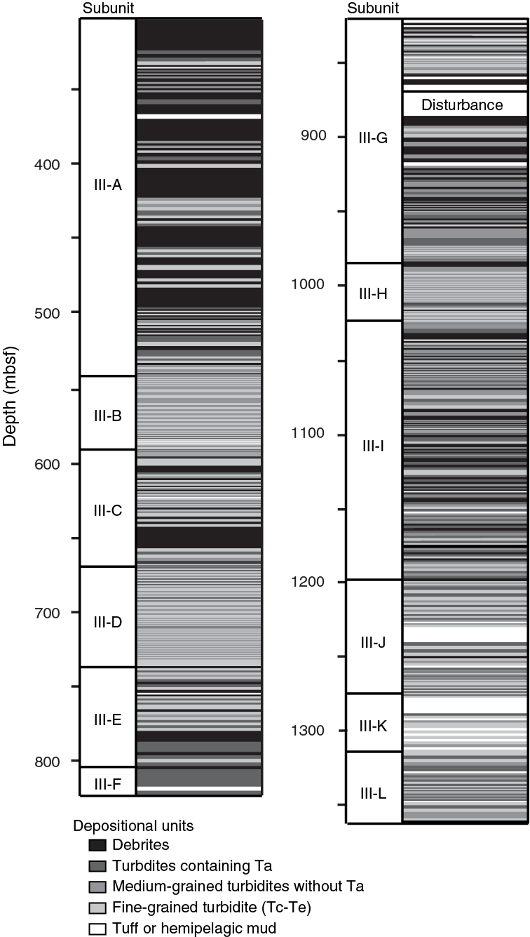
Figure F7. Distribution of depositional units within Unit III.
Table T6. Depositional unit types on a core-to-core basis. Available in TRENDS in Supplementary material.
Stratigraphic subunit designations for Units IV and III
Shipboard scientists placed the Unit IV/III boundary at the first downhole occurrence of a thick mudstone interval below the thick interval of debrite and turbidite in Section 351-U1438E-55R-3. Unit IV is distinguished by a significant radiolarian content in the top 50 m of the unit. This is distinguished as Subunit IV-A, which contains thin and medium fine-grained turbidites. The underlying interval (Subunit IV-B) is characterized by fine-grained turbidites that contain minimal sand, whereas the thin Subunit IV-C is mainly hemipelagic mudstone. Note that Unit IV subunit designators follow the IODP format where A equals the youngest and then designators progress through the alphabet with increasing relative age. This format was continued into Units III and II.
As the thickest of the Site U1438 units (1052.33 m), Unit III contains the most variety of depositional unit characteristics. Unit III is distinguished from Unit IV in that it contains fine-, medium-, and coarse-grained turbidites as well as debrites in coarsening-upward packages.
Whereas shipboard scientists did not attempt to divide this thick unit into subunits, the detailed data collected in this study facilitated subunit divisions. Following the illustration and classification of all the cores, core summary columns for Units III and II were printed and combined end-to-end, forming a 25 m long high-resolution stratigraphic log. Large-scale subunits could then be discerned based on changes in grain size, bedding, facies classes, and depositional unit types present. Unit III is distinguished by periodic pulses of debrites. Debrite-rich and debrite-poor subunits generally alternate. Unit III subunits are broadly based on relative debrite versus turbidite content, where intervals of cores containing debrites were grouped together. Each debrite-rich subunit contains a gradual buildup of debrite content and thickness before dropping abruptly, which defines the upper contact of the subunits. Debrite-poor subunits may contain tuff beds, mudstone beds, and isolated debrites, but the dominant depositional units are turbidites. Throughout Unit III, the sediment accumulation rate varied but peaked at significant occurrences of debrites. Unit III is divided into twelve subunits, labeled “III-L” to “III-A” from oldest to youngest as summarized in Table T7 and Figure F5. These are described in detail below.
Table T7. Characteristics of each subunit. Available in TRENDS in Supplementary material.
Subunit III-L
Subunit III-L is composed of thin sand to mud turbidites (Figure F8A; Table T4) and scattered intervals of hemipelagic mudstone (Figure F8B). Drilling brecciation and disturbance were common, so intact bedding contacts were not often recognizable. Apparent depositional unit (turbidite) thicknesses are <10 cm, the thinnest of all Unit III subunits. The dominant facies class, from Pickering et al. (1986), is Class C (Table T1), more specifically Classes C2.2 (sand and mud couplets 10–30 cm thick) and C2.3 (sand and mud couplets <10 cm), with thicknesses decreasing upsection within the subunit. Most turbidites exhibit either Tade or Tbde patterns. Bouma (1962) division Tc is absent aside from rare occurrences of complete and nearly complete turbidites.

Figure F8. Subunit III-L thin turbidites and unstructured hemipelagic mud beds.
Subunit III-K
Subunit III-K contains a relatively high percentage of tuff/lapillistone. A relatively structureless 11 m thick tuff bed (Figure F9A) occurs at the top of the subunit. The relative content of primary volcanic material (ash) builds upsection before dropping from 100% to 0% at the contact with Subunit III-J. Between volcanic deposits are fine-grained turbidites and medium-grained turbidites with partial to nearly complete Bouma sequences (Figure F9B). Turbidites are affected by soft-sediment deformation at the bottom of the subunit coherent at the top where thicknesses exceed 30 cm. Facies Classes B (sandstone), C, D (siltstone), and E (mudstone) (Table T1) occur in nearly equal proportions.
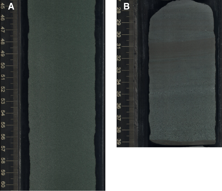
Figure F9. Subunit III-K thick primary tuff bed and medium-grained turbidite.
Subunit III-J
Subunit III-J is primarily thin sandy turbidites, with minor isolated basin floor hemipelagic mudstones, debrites, and primary volcanic deposits. Core 351-U1438E-42R is a primary tuff and lapillistone thicker than 2.6 m exhibiting faint lamination (Figure F10A). Turbidites are either fine-grained or incomplete medium-grained Bouma (1962) sequences (Figure F10B). Turbidite thicknesses increase upsection from ~20 to >50 cm. In addition, the primary facies class is Class E, corresponding to the abundance of mudstone (Table T1), although Classes B, C, and D are introduced near the top of the subunit.

Figure F10. Subunit III-J primary tuff bed and Tbce turbidite.
Subunit III-I
Subunit III-I is a primarily debrite-rich subunit with intermixed fine-, medium-, and coarse-grained turbidites. Two clusters of debrites are separated by a 25 m interval of ~50 cm thick Tabce turbidites. Both debrite clusters build up to about 85% debrite core percentage before abruptly dropping to 0%. The abrupt top of the second cluster is the boundary with overlying Subunit III-H. Within the debrite clusters are periodic 2–5 m thick fine- and medium-grained turbidite intervals (Figure F11A) overlain by debrite intervals (Figure F11B). Facies Classes A and B are dominant, meaning the dominant lithologies are conglomerate, sandstone, and siltstone (Table T1). Depositional unit thicknesses average <30 cm; however, contacts were often not recovered.
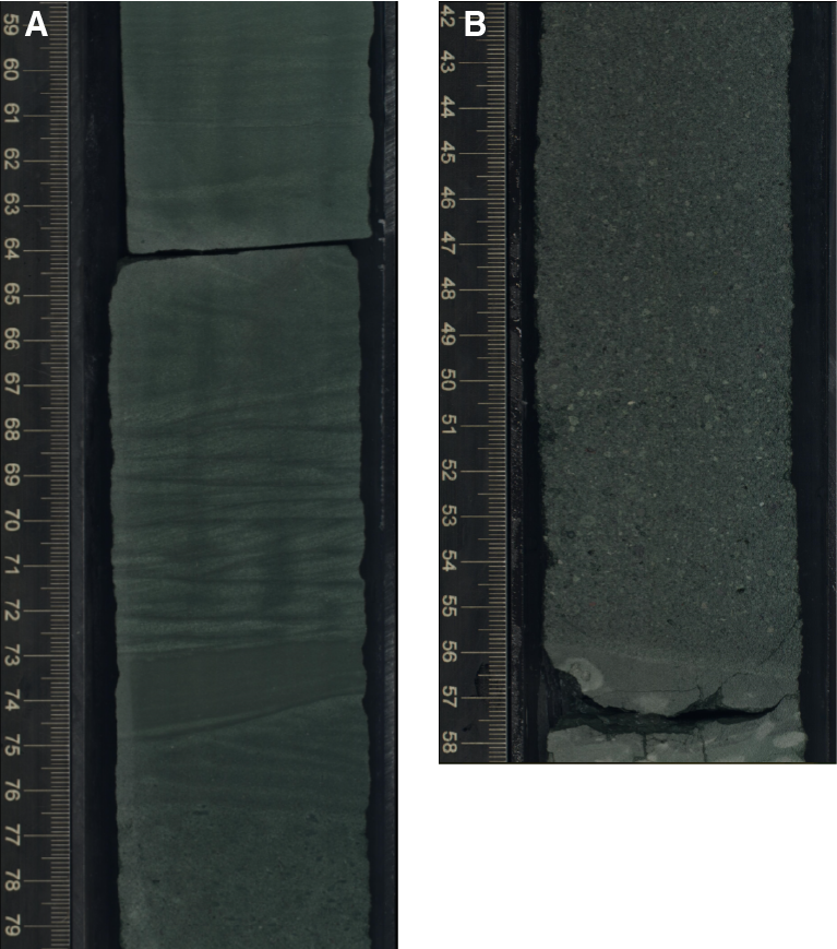
Figure F11. Subunit III-I turbidite interval and base of thick debrite bed.
Subunit III-H
Subunit III-H is dominated by fine- to medium-grained turbidites (Figure F12). As an exception, Core 351-U1438E-19R contains isolated thin debrites, a single primary lapillistone bed, and a single coarse-grained turbidite among the dominant thin fine-grained turbidites. Siltstone is the subunit’s dominant lithology, meaning facies Classes D1.1 and D2.4 are dominant. Facies Classes A and B exist only within the most complete turbidites. The primary average turbidite thickness is >50 cm; however, two 2–3 m packages of ~10 cm turbidites are present.
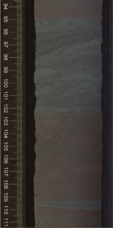
Figure F12. Typical Subunit III-H turbidite sequence.
Subunit III-G
Subunit III-G contains a relatively high percentage of debrites. Debrites build up to a proportion of about 50% in Core 351-U1438D-72R before gradually decreasing to 0%, marking the boundary with overlying Subunit III-F. A highly faulted zone (Figure F13A) marks the transition from Hole U1438E to U1438D where depositional units cannot be confidently interpreted. Below the faulted zone, gravel-sized clast content is very high and facies Classes A and B dominate. Similar to Subunit III-I, the bottom of Subunit III-G contains alternating turbidite (facies Classes C, D, and E; Figure F13B) and debrite (Figure F13C) intervals, with coarsening-upward trends. Debrites are consistently thicker than 1 m.
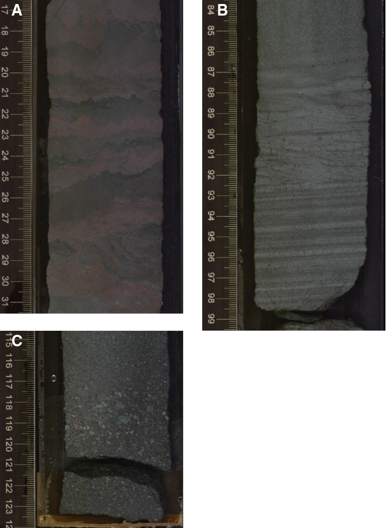
Figure F13. Subunit III-G disturbed, microfaulted zone, turbidite interval between debrites, and debrites.
Subunit III-F
Subunit III-F is the thinnest subunit in Unit III and is composed entirely of turbidites. The primary lithologies are sandstone and siltstone, which are organized in very thin nearly complete medium-grained turbidites (Figure F14). No mudstone and minor gravel are present. One tuff bed occurs near the bottom of the subunit within a series of drilling-brecciated turbidites. Thin (<10 cm) turbidites of facies Class D2.5 are interrupted by short intervals of turbidites thicker than 30 cm (facies Class B1.1).
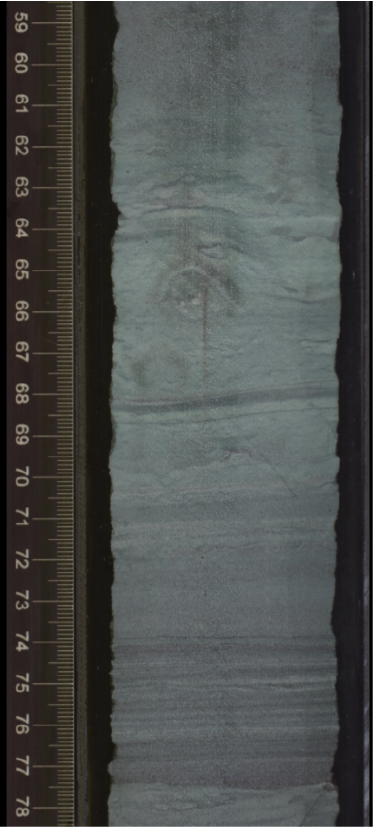
Figure F14. Typical turbidite from thin Subunit III-F.
Subunit III-E
Subunit III-E has a relatively high proportion of debrites (Figure F15A) that alternate with fine- and medium-grained turbidite intervals. Most medium-grained turbidites contain the Ta Bouma division but those that do not are grouped together in relatively thin intervals with depositional unit thicknesses <30 cm (Figure F15B). Debrites and Ta-containing turbidites are <1 m thick. Intervals of thin fine- and medium-grained turbidites are common at the bottom of the subunit but are thicker and less common near the top. Facies Classes A, B, and D are present, meaning all lithologies are present except mudstone.
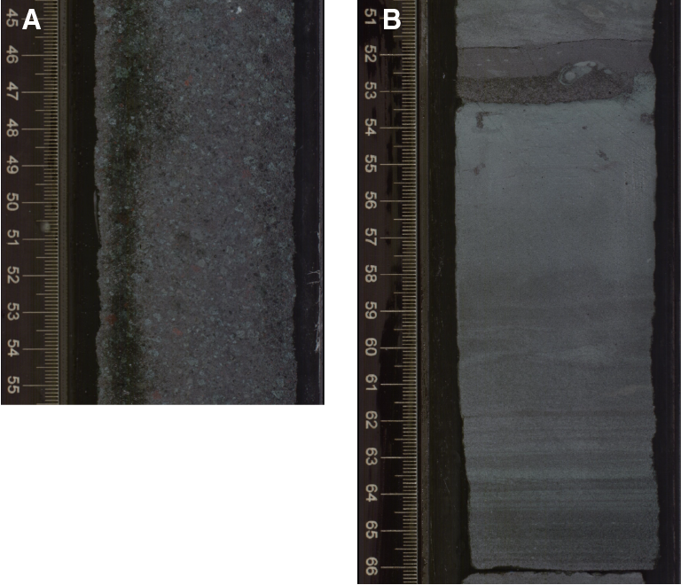
Figure F15. Subunit III-E debrites and turbidites within debrite intervals.
Subunit III-D
Subunit III-D is fine- and medium-grained turbidite dominated and is the most silt-rich section in Unit III. Fine-grained turbidites overprinted by bioturbation are accompanied by isolated medium-grained turbidites (Figure F16A). Near the top of the subunit coarse-grained turbidites are introduced (Figure F16B) and transition into the overlying debrite-rich Subunit III-C. Depositional unit thickness ranges from 10 cm for the fine-grained turbidites to 75 cm for the medium- and coarse-grained turbidites at the top. Facies Class D2.5 (disturbed sequences of sand to silt turbidites) is prominent, and Classes B1.1 and B2.1 accompany the medium- and coarse-grained turbidites.
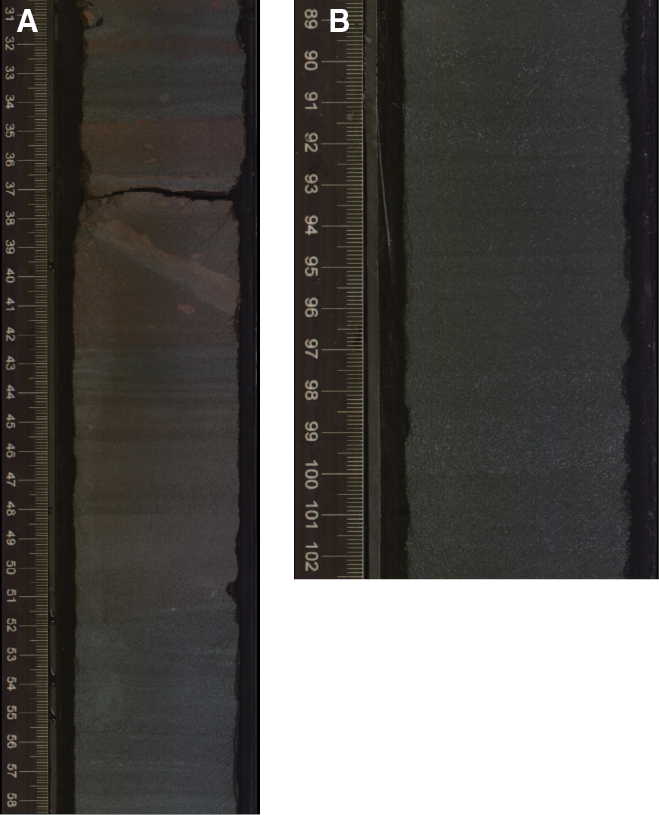
Figure F16. Subunit III-D fine-, medium-, and coarse-grained turbidites.
Subunit III-C
Subunit III-C contains two intervals with a high debrite concentration within medium-grained turbidites. Most depositional unit contacts are not recovered, owing to drilling disturbance, but where recovered, depositional units are <1 m thick. A 16 m thick debris flow deposit makes up the bottom of the subunit (Figure F17A) and is the start of the first buildup of debrites that continues into the overlying 30 m of section. Turbidites are sand-to-silt Tbcde varieties (Figure F17B) with zones of soft-sediment deformation–disturbed fine-grained turbidites. Mudstone is present between the debrite intervals. Debrite-rich zones contain facies Classes A and B, whereas intervening turbidites are facies Classes D2.4 and D2.5.

Figure F17. Subunit III-C part of 16 m debrite bed and Tbcde turbidite.
Subunit III-B
Subunit III-B is made up entirely of fine- to medium-grained turbidites. Turbidites are generally thin (<30 cm) (Figure F18A), and the thickest turbidite is 0.75 m (Figure F18B). The entire subunit is fairly uniform in character. Exceptions are one tuff bed, one mudstone bed, and a few Ta turbidites at the bottom of the subunit. There is an upsection transition from mudstone rich (facies Class E), the highest mudstone content of Unit III, to siltstone rich (facies Class D).

Figure F18. Subunit III-B thin medium-grained turbidites and Tbcde turbidite.
Subunit III-A
Subunit III-A contains a very high proportion of debrites (Figure F19A) with few interbedded turbidites. Debris flow proportion builds from 0% in Core 351-U1438D-37R to 100% in Core 31R and remains high to the top of the subunit (Unit III/II boundary). Cores 25R and 16R contain relatively thin-bedded (10–50 cm) fine- and medium-grained siltstone-rich turbidite intervals (Figure F19B) that exhibit abrupt contacts with the surrounding debrite intervals. Debrites range from 1 m thick to <20 m thick (in Cores 22R to 24R), but thickness determinations are different because approximately 20% of depositional contacts were not recovered. The primary lithologies are conglomerate and coarse sandstone (facies Class A).
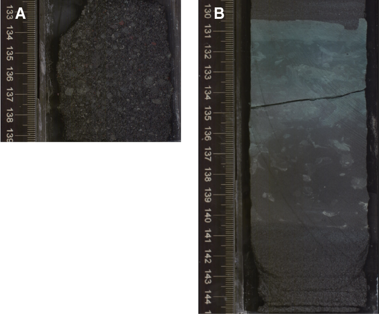
Figure F19. Subunit III-A debrite bed below Unit III/II boundary and fine-grained turbidite.
Stratigraphic subunit designations for Unit II
The Unit III/II boundary was placed at 309.55 mbsf, within Core 351-U1438D-12R by shipboard scientists. It is marked by an abrupt shift from the largely gravel-rich Unit III to the sandstone-to-mudstone turbidite- and hemipelagic mud–rich Unit II (Figure F20). The exact boundary was not recovered but was placed at the top of the youngest gravel-rich interval in a drilling-brecciated zone.
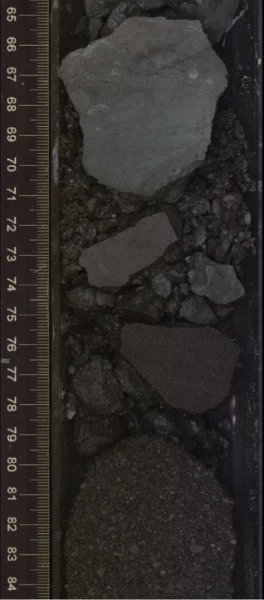
Figure F20. Unit III/II boundary.
Unit II subunits are divided based on lithologic changes and degree of drilling disturbance of variably lithified subunits. This unit is primarily mud and mudstone, with a varying sandstone content that corresponds to the ratio of medium-grained turbidites to fine-grained turbidites. Drilling disturbance and hemipelagic mud proportions increase upsection. Unit II is divided into three subunits, labeled “II-C,” “II-B,” and “II-A” from oldest to youngest (Figure F5A; Table T4).
Subunit II-C
Subunit II-C immediately overlies the Unit III/II boundary and is composed of mud-rich turbidites. Individual bed contacts are indistinguishable due to soft-sediment deformation (Figure F21) and drilling-related disturbance but turbidite divisions are discernible. The entire subunit is made up of fine-grained turbidites (Figure F21) with scattered sandy medium-grained turbidites. Sandy beds in Subunit II-C are the thickest of all Unit II. Facies Classes E1.1 and D1.1 dominate with lesser facies Class B2.1 (sandy beds).
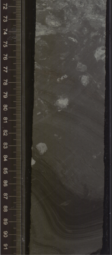
Figure F21. Prominent convoluted fine-grained turbidite, Subunit II-C.
Subunit II-B
Subunit II-B is too disturbed by drilling and bioturbation (Figure F22) to confidently apply any classification scheme to depositional units. Unconsolidated ash and lapilli beds are present in the upper two cores of the subunit (Cores 351-U1438B-25X and 24X). Sandstone is rare—yielding to an increased proportion of bioturbated mudstone (facies Class E1.1) and siltstone (facies Class D1.1).
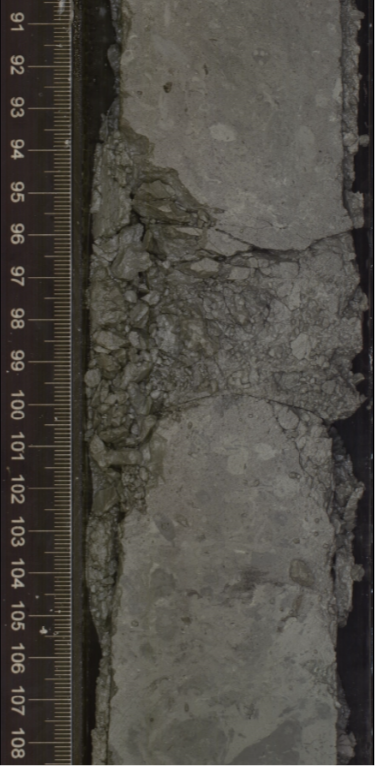
Figure F22. Drilling disturbance (brecciation) in fine-grained heavily bioturbated beds, Subunit II-B.
Subunit II-A
Subunit II-A makes up the top portion of Unit II and transitions into the hemipelagic mud of Unit I. The bottom 12 m consists of sand-rich turbidites (facies Classes B1.1 and 2.1) (Figure F23A) and a relatively high volcanic ash content. Drilling brecciation means fine-grained depositional units cannot be confidently interpreted. Sand content decreases upsection. The top 17.5 m consists of unlithified hemipelagic mud (Class E1.1) with altered ash and no visible structures other than burrows (Figure F23B).
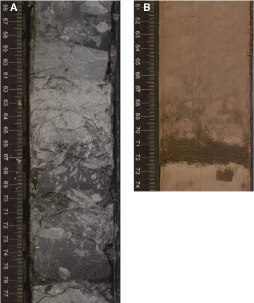
Figure F23. Subunit II-A final turbidites and hemipelagic mud and dark, fining-upward primary ash.
Unit II/I boundary
The Unit II/I boundary is a shift from sandstone-to-mudstone turbidites with hemipelagic mud in Unit II to massive and uninterrupted hemipelagic mud in Unit I. This occurs at 160.25 mbsf, within Core 351-U1438B-18H.
Acknowledgments
This work was supported by grants awarded to Marsaglia from NSF (OCE-1503694) and Ocean Leadership and a GSA grant awarded to Johnson. We would like to thank the core description team from International Ocean Discovery Program (IODP) Expedition 351 for the excellent data set that they created, without which this study would not have been possible.
References
Arculus, R.J., Ishizuka, O., Bogus, K., Aljahdali, M.H., Bandini-Maeder, A.N., Barth, A.P., Brandl, P.A., do Monte Guerra, R., Drab, L., Gurnis, M.C., Hamada, M., Hickey-Vargas, R.L., Jiang, F., Kanayama, K., Kender, S., Kusano, Y., Li, H., Loudin, L.C., Maffione, M., Marsaglia, K.M., McCarthy, A., Meffre, S., Morris, A., Neuhaus, M., Savov, I.P., Sena Da Silva, C.A., Tepley, F.J., III, van der Land, C., Yogodzinski, G.M., and Zhang, Z., 2015a. Expedition 351 methods. In Arculus, R.J., Ishizuka, O., Bogus, K., and the Expedition 351 Scientists, Izu-Bonin-Mariana Arc Origins. Proceedings of the International Ocean Discovery Program, 351: College Station, TX (International Ocean Discovery Program). https://doi.org/10.14379/iodp.proc.351.102.2015
Arculus, R.J., Ishizuka, O., Bogus, K., Aljahdali, M.H., Bandini-Maeder, A.N., Barth, A.P., Brandl, P.A., do Monte Guerra, R., Drab, L., Gurnis, M.C., Hamada, M., Hickey-Vargas, R.L., Jiang, F., Kanayama, K., Kender, S., Kusano, Y., Li, H., Loudin, L.C., Maffione, M., Marsaglia, K.M., McCarthy, A., Meffre, S., Morris, A., Neuhaus, M., Savov, I.P., Sena Da Silva, C.A., Tepley, F.J., III, van der Land, C., Yogodzinski, G.M., and Zhang, Z., 2015b. Expedition 351 summary. In Arculus, R.J., Ishizuka, O., Bogus, K., and the Expedition 351 Scientists, Izu-Bonin-Mariana Arc Origins. Proceedings of the International Ocean Discovery Program, 351: College Station, TX (International Ocean Discovery Program). https://doi.org/10.14379/iodp.proc.351.101.2015
Arculus, R.J., Ishizuka, O., Bogus, K., Aljahdali, M.H., Bandini-Maeder, A.N., Barth, A.P., Brandl, P.A., do Monte Guerra, R., Drab, L., Gurnis, M.C., Hamada, M., Hickey-Vargas, R.L., Jiang, F., Kanayama, K., Kender, S., Kusano, Y., Li, H., Loudin, L.C., Maffione, M., Marsaglia, K.M., McCarthy, A., Meffre, S., Morris, A., Neuhaus, M., Savov, I.P., Sena Da Silva, C.A., Tepley, F.J., III, van der Land, C., Yogodzinski, G.M., and Zhang, Z., 2015c. Site U1438. In Arculus, R.J., Ishizuka, O., Bogus, K., and the Expedition 351 Scientists, Izu-Bonin-Mariana Arc Origins. International Ocean Discovery Program, 351: College Station, TX (International Ocean Discovery Program). https://doi.org/10.14379/iodp.proc.351.103.2015
Arculus, R.J., Ishizuka, O., Bogus, K.A., Gurnis, M., Hickey-Vargas, R., Aljahdali, M.H., Bandini-Maeder, A.N., Barth, A.P., Brandl, P.A., Drab, L., do Monte Guerra, R., Hamada, M., Jiang, F., Kanayama, K., Kender, S., Kusano, Y., Li, H., Loudin, L.C., Maffione, M., Marsaglia, K.M., McCarthy, A., Meffre, S., Morris, A., Neuhaus, M., Savov, I.P., Sena, C., Tepley, F.J., III, van der Land, C., Yogodzinski, G.M., and Zhang, Z., 2015d. A record of spontaneous subduction initiation in the Izu-Bonin-Mariana arc. Nature Geoscience, 8:728–733. https://doi.org/10.1038/ngeo2515
Boggs, S., Jr., 2011. Principles of Sedimentology and Stratigraphy (5th edition): Upper Saddle River, New Jersey (Pearson).
Bouma, A.H., 1962. Sedimentology of Some Flysch Deposits: A Graphic Approach to Facies Interpretation: Amsterdam (Elsevier).
Lowe, D.R., 1982. Sediment gravity flows, II. Depositional models with special reference to the deposits of high-density turbidity currents. Journal of Sedimentary Petrology, 52(1):279–297. http://jsedres.sepmonline.org/cgi/content/abstract/52/1/279
Pickering, K., Stow, D., Watson, M., and Hiscott, R., 1986. Deep-water facies, processes, and models: a review and classification scheme for modern and ancient sediments. Earth-Science Reviews, 23(2):75–174. https://doi.org/10.1016/0012-8252(86)90001-2
Pickering, K.T., and Hiscott, R.N., 2015. Deep Marine Systems: Processes, Deposits, Environments, Tectonics and Sedimentation: Chichester, United Kingdom (Wiley-Blackwell).
Pickering, K.T., Hiscott, R.N., and Hein, F.J., 1989. Deep-Marine Environments: Clastic Sedimentation and Tectonics: London (Unwin Hyman).
Stow, D.A.V., and Shanmugam, G., 1980. Sequences of structures in fine-grained turbidites: comparison of recent deep-sea and ancient flysch sediments. Sedimentary Geology, 25(1–2):23–42. https://doi.org/10.1016/0037-0738(80)90052-4
Appendix A
Section-scale stratigraphic columns
Section-scale (up to 1.5 m) stratigraphic columns are available in STRATCOL in Supplementary material.
Appendix B
Core-scale stratigraphic columns
Core-scale (up to 9.5 m) stratigraphic columns are available in STRATCOL in Supplementary material.
1 Johnson, K., Waldman, R., and Marsaglia, K.M., 2017. Data report: sedimentary columns with facies and bedding for Units II–IV at IODP Site U1438. In Arculus, R.J., Ishizuka, O., Bogus, K., and the Expedition 351 Scientists, Izu-Bonin-Mariana Arc Origins. Proceedings of the International Ocean Discovery Program, 351: College Station, TX (International Ocean Discovery Program). https://doi.org/10.14379/iodp.proc.351.201.2017
2 Department of Geological Sciences, California State University, USA. Correspondence author: Kathie.marsaglia@csun.edu
This work is distributed under the Creative Commons Attribution 4.0 International (CC BY 4.0) license. 