Fryer, P., Wheat, C.G., Williams, T., and the Expedition 366 Scientists
Proceedings of the International Ocean Discovery Program Volume 366
publications.iodp.org
https://doi.org/10.14379/iodp.proc.366.104.2018

Site U14911
P. Fryer, C.G. Wheat, T. Williams, E. Albers, B. Bekins, B.P.R. Debret, J. Deng, Y. Dong, P. Eickenbusch, E.A. Frery, Y. Ichiyama, K. Johnson, R.M. Johnston, R.T. Kevorkian, W. Kurz, V. Magalhaes, S.S. Mantovanelli, W. Menapace, C.D. Menzies, K. Michibayashi, C.L. Moyer, K.K. Mullane, J.-W. Park, R.E. Price, J.G. Ryan, J.W. Shervais, O.J. Sissmann, S. Suzuki, K. Takai, B. Walter, and R. Zhang2
Keywords: International Ocean Discovery Program, IODP, JOIDES Resolution, Expedition 366, Site 1200, Site U1491, Site U1492, Site U1493, Site U1494, Site U1495, Site U1496, Site U1497, Site U1498, Mariana, Asùt Tesoru Seamount, Conical Seamount, Fantangisña Seamount, South Chamorro Seamount, Yinazao Seamount, Cretaceous seamount, subduction, subduction channel, forearc, seismogenic zone, mud volcano, fluid discharge, serpentinite, carbonate, harzburgite, clasts, ultramafic rock, breccia, gypsum, mudstone, chert, reef limestone, volcanic ash, guyot, CORK, CORK-Lite, screened casing
MS 366-104: Published 7 February 2018
Site summary
Site U1491 is located on the flank of Yinazao Seamount (informally known as Blue Moon Seamount) about 55 km west of the Mariana Trench. This site was chosen to characterize the composition and timing of various serpentinite mudflows to assess transport and alteration conditions on the midflank (Figure F1). Three holes were drilled at this site. The seafloor was tagged in Hole U1491A, and an advanced piston corer (APC) core was taken from inside the drill pipe without the piston core being fired (see Operations); 1.32 m of brown to dark brown clayey pelagic sediment with one mafic and one carbonate pebble was recovered. The drill string was moved slightly to spud Hole U1491B and recovered a total of 19.4 m: 5.45 m of brown muddy sediment, 1.19 m of carbonate fragments mixed with brown mud, 6.34 m of greenish serpentinite pebbly mud with one mafic pebble, and 3.15 m of bluish gray serpentinite pebbly mud. Beneath the serpentinite mud were cuttings of serpentinized ultramafic rocks (probably fall-in of rocks drilled farther up the hole), carbonate, and a very small amount of serpentinite mud. This material extended to the bottom of the hole at 19.4 meters below seafloor (mbsf).
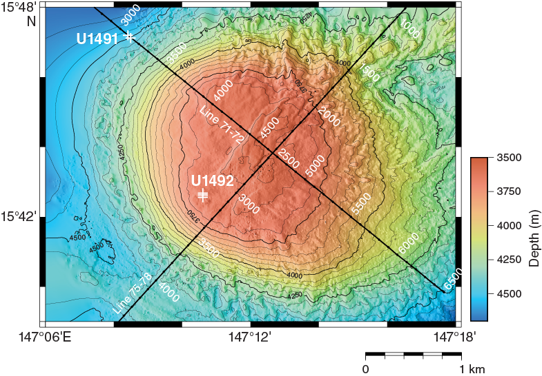
Figure F1. Bathymetric map.
Hole U1491C is positioned 200 m downslope to the northwest and recovered 24.72 m of material from a cored advance of 34.2 m. The recovered lithology was generally similar to that in Hole U1491B. The top of Hole U1491C contained 2.26 m of brown sediment similar to that in Hole U1491B. However, a carbonate cobble is present in Section 366-U1491C-2H-5, 133 cm (Figure F2), and all of Section 2H-6 and half of Section 3F-1 consists of carbonate mixed with brown mud and lithic granules to pebbles. Immediately below the carbonate is a unit of highly mottled serpentinite mud and heavily serpentinized/altered clasts of ultramafic rock. Mottling varies from red-brown to black, and there are alteration halos (some black, some red-brown) in the serpentinite mud matrix around rock clasts. A second layer of mixed carbonate and ultramafic gravel with breccia fragments lies beneath the mottled serpentinite mud. Beneath the gravel layer is another serpentinite mud layer with a bluish gray matrix and dark mottling and a third layer of carbonate fragments mixed with serpentinized ultramafic rocks and some red-brown granules to pebbles, some of which are breccias, in a thin layer of serpentinite mud. Toward the bottom of the hole, the serpentinite mud matrix becomes less rich in rock clasts (except for some fall-in gravel at the top of cores) but contains fragments of carbonate to the bottom of the hole. A fragment of carbonate material in Section 8F-1 has ribs or ridges (pecten or scallop shell fragment?) (Figure F3).

Figure F2. Fossilized high-spire gastropod.

Figure F3. Fossilized pecten or scallop shell fragment.
Ten whole-round samples were collected at Site U1491 for interstitial water extraction. The chemical composition of these fluids is much like that of bottom seawater in the upper 10 m of the sediment matrix, and dissolved methane and hydrogen concentrations are low. However, the composition of interstitial waters deviates from bottom seawater values lower in the cored section in the serpentinite muds. At depth, pH and strontium concentrations are generally higher than seawater values, whereas alkalinity is lower, consistent with trends observed in interstitial waters from the summit conduit (Site U1492) (Hulme et al., 2010). These trends indicate that serpentinization reactions remain active in flank-derived materials or the trends result from diffusive transport and diagenetic reactions that allow for infiltration of seawater into the serpentinite mud deposits.
Samples were collected for shore-based microbiological studies. To assess possible artifacts from drilling operations, tracers were pumped into the drill string prior to and during core recovery (see Microbiology). Tracer analyses indicate that most of the microbiology whole-round samples are suitable for shore-based analyses.
The physical property data collected at Site U1491 are in good agreement with the lithology data mentioned above. The occurrence of pelagic deposits at the top of the section indicates that mudflows have not been active on the northeastern flank of Yinazao Seamount for some time; these findings will be constrained by shore-based dating methods. The physical properties of the underlying serpentinite mud at Site U1491 are consistent with those measured on other Mariana forearc seamounts (Conical Seamount, Ocean Drilling Program [ODP] Leg 125 [Fryer, Pearce, Stokking et al., 1992]; South Chamorro Seamount, ODP Leg 195 [Salisbury, Shinohara, Richter, et al., 2002]), as well as the serpentinite mud deposits recovered at the summit of Yinazao Seamount at Site U1492 during this expedition. The high peak magnetic susceptibility values of about 10−2 SI highlight the presence of magnetite in serpentinite mud, classically associated with the process of serpentinization of ultramafic rocks (e.g., Bonnemains et al., 2016). The significant variations of this physical property reflect heterogeneities in magnetite content associated with the ratio of muds to clasts. The effect of compaction is suggested by the overall increasing trend in gamma ray attenuation (GRA) bulk density with depth, with average values of ~1.8–2.0 g/cm3, but the overall high bulk density values (>2.0 g/cm3) in the serpentinite mud (6–16 mbsf) suggest that additional porosity-reducing processes are also in play.
Downhole measurements consisted of two temperature measurements using the advanced piston corer temperature tool (APCT-3) in the APC coring shoe. Because of heave and the shallow depth of the measurements (9.5 and 19.4 mbsf), temperatures recorded with the sensors were affected by movement of the bottom-hole assembly (BHA) while the measurements were collected, resulting in temperature estimates with a degree of uncertainty. Nevertheless, the thermal gradient was 20°–30°C/km, and the calculated heat flow was 30–44 mW/m2, comparable to measurements on the flanks of other nearby serpentinite mud volcanoes.
Natural remanent magnetization (NRM) intensities vary with lithostratigraphic unit and magnetic susceptibility (see Physical properties); for example, high intensities averaging 0.5 A/m were measured in the serpentinite mud from Hole U1491B, lithostratigraphic Unit II. Declination results followed by principal component analyses (PCA) of demagnetization data revealed no clear correspondence in declination and inclination changes in the pelagic sections. Because these sections contain sandy silt beds, two or more dipping lithologic contacts, and some gravel- and pebble-sized clasts, these sections were not ideal for recording the paleomagnetic field with sufficient fidelity to characterize age-related reversals.
Background and objectives
Site U1491 is located on the lower northwest flank of Yinazao Seamount (Figures F1, F4), a serpentinite mud volcano that lies on the eastern edge of a forearc graben about 55 km from the Mariana Trench axis (see Figure F1 in the Expedition 366 summary chapter [Fryer et al., 2018b]). Of the three mud volcanoes cored during Expedition 366, it is the closest to the trench, and based on multichannel seismic (MCS) reflection data, the subducting slab lies approximately 13 km below its base (Oakley, 2008; Oakley et al., 2008). Like the many other serpentinite mud volcanoes that populate the southern half of the Mariana forearc (between the trench and the volcanic arc), Yinazao Seamount is situated along a zone of weakness in the overriding plate’s lithosphere. The fault that controlled the growth of the edifice has a northeast trend.

Figure F4. MCS Line EW0202 71-72.
The plan for drilling at Site U1491 was to penetrate the lower northwest slope of the mud volcano. On the basis of bathymetry and side-scan data, it appeared that this region of the seamount was the least deformed by slumping. In contrast, the eastern and southeastern sectors of the seamount’s flanks are disrupted by general downslope movement toward the trench. This deformation is likely caused by seismic activity in the forearc lithosphere and in the decollement beneath the region around Yinazao Seamount. A cluster of earthquakes in 1990 and 1991 in this area was followed by active seismicity lasting at least until 2002 (Engdahl et al., 1998; Fryer, 2012).
A MCS profile collected across Yinazao Seamount at Site U1491 shows reflectors dipping slightly southeast, consistent with interpretations by Oakley et al. (2007) that serpentinite mud volcanoes essentially sag under their own weight and extend their distal edges over time. Drilling at Site U1491 on the lower northeast flank was expected to recover serpentinite mudflow materials older than those at the summit.
The plan was to core two 50 m deep boreholes separated by 200 m and a third borehole up to 250 m deep, forming a downflank transect. The location of the transect was chosen to (1) intersect mudflows on the midflank; (2) potentially date discrete mudflows paleontologically, should there be sediment layers between them; (3) determine variability of mudflow thickness; (4) investigate potential systematic variability in degree of serpentinization (possible lower degrees of alteration at the initiation of mud volcanism, e.g., conduit “throat clearing”); (5) examine transport conditions; and (6) provide a measure for the scale of potential flow characteristics.
Operations
After completing operations to remove part of the CORK body from Site 1200, the ship transited 137 nmi to Site U1491 in 14.5 h at an average speed of 9.8 kt, arriving in the area of Site U1491 at 1050 h on 15 December 2016. (All dates and times are ship local times.)
Hole U1491A
A seafloor depth measurement using the precision depth recorder (PDR) was taken once the ship was in position; however, the depth was 222 m shallower than expected. Initially, the discrepancy was thought to be an artifact of being on the steep-sided flank (~10° slope) of the serpentinite mud volcano; however, the operations summary had an erroneous position coordinate with a ~5 nmi error. With the drill string at 1855 meters below rig floor (mbrf), the ship was moved in dynamic positioning (DP) mode to the corrected location coordinates. The new PDR seafloor depth was 4442 meters below sea level (mbsl), which was different from the depth in the Scientific Prospectus (4500 mbsl) because of the slope geometry: the first arrival of the PDR 3.5 kHz signal came from upslope rather than from directly under the ship. To be certain of the seafloor depth, the seafloor was tagged with the core bit at 4494 mbsl, starting Hole U1491A at 0645 h on 16 December 2016. During the tagging process, sediment entered the bit and BHA and was then collected with the APC core barrel from inside the BHA without the core barrel being fired. The core barrel was recovered at 0800 h with 1.3 m of recovery, including three distinct mudlines, likely resulting from ship heave causing the BHA to tag the seafloor three or more times (Table T1). This single core constitutes Hole U1491A, and its exact location is difficult to specify because of the way it was collected.
Table T1. Site U1491 core summary. Download table in CSV format. View PDF table.
Hole U1491B
At 1015 h, Hole U1491B was started at 4503.4 mbrf. Oriented APC coring continued using the advance by recovery method, penetrating to 19.4 mbsf and recovering 19.0 m of core (98%) (Table T1). Coring was halted due to the continued presence of coarse gravel. All cores were incomplete strokes. Formation temperature measurements using the APCT-3 were attempted at 13.2 and 19.4 mbsf. The drill string was pulled out of the hole, clearing the seafloor at 2325 h.
Hole U1491C
Hole U1491C is 200 m northwest (downslope) of Hole U1491B, and coring started at 0025 h on 17 December 2016 at 4492.5 mbsl. The first two cores are oriented APC cores, and then because of incomplete stroke a switch was made to half-length APC (HLAPC) coring and advanced by recovery for Cores 366-U1491C-3F through 8F. The barrel did not fully stroke for any of the cores from this hole, and recovery ranged from 1 to 4.7 m, prompting a switch to extended core barrel (XCB) coring. XCB Core 9X required 70 min of rotating time to cut the core and substantial effort to clean out 5 m of coarse gravel fill prior to cutting the core. Core 9X contained only 0.27 m recovery due to a jammed piece of core in the XCB cutting shoe. A second XCB core barrel was deployed, and the bit was advanced to 43.9 mbsf when the driller noticed a loss of torque and pump pressure. Two unsuccessful attempts were made to recover the core barrel, but the overshot did not engage the pulling neck on the barrel. Upon recovery of the sinker bar string, the overshot had all of its shear pins intact; however, the core line was damaged on both runs. Recognizing that something was wrong with the drill assembly (and fearing a BHA failure), the drill string was recovered. When the drill string was recovered, the BHA had failed and the following were lost in the hole: the bit, a nonmagnetic drill collar, an APC/XCB outer core barrel assembly, and an XCB core barrel assembly. At 0000 h on 18 December, the ship started the 5 nmi transit to Site U1492 in DP mode.
Lithostratigraphy
Materials recovered at Site U1491 include pelagic clays, carbonate pebbles and cobbles, and serpentinite muds, representing changes in emplacement environments (Figure F5). The drill site on the flank of Yinazao Seamount (Figure F6) shows a subtle break in slope with a slight slope decrease and potential depositional basin where Site U1491 is located. These slope characteristics, coupled with the discovery of an active serpentinite spring during a dive of the remotely operated vehicle Jason (Fryer et al., in prep) on the mud volcano summit and the presence of carbonate cobbles with shell, coral, and gastropod fossils topped by pelagic sediment materials, accounts for the variety of lithologic units and the sharp and distinct lithologic boundaries between them in this shallow (<50 m) depth range. Holes U1491B and U1491C are separated by 200 m, and although there are some similarities in the lithostratigraphy in both holes, there are also significant differences. We therefore describe the lithostratigraphy for each hole separately.
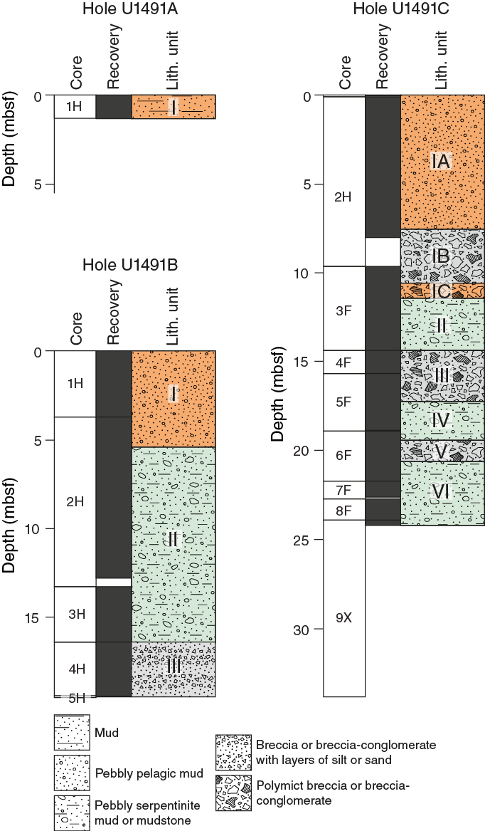
Figure F5. Lithostratigraphic summary.
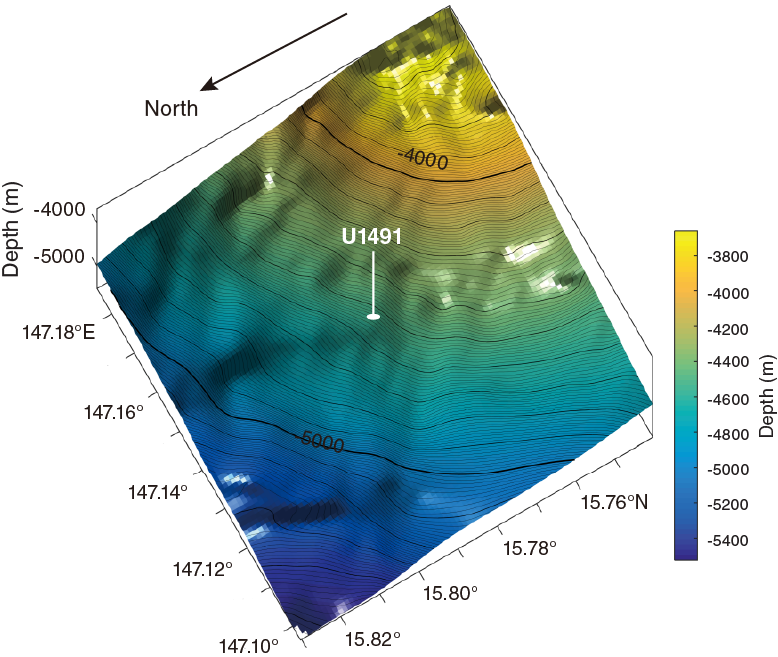
Figure F6. Yinazao Seamount and Site U1491.
Hole U1491A
Hole U1491A consists of 1.32 m of massive brown to dark brown clayey pelagic mud with lithic and carbonate clasts. The lithic clasts are dominantly brown mudstone; however, some may be altered arc volcanic rocks. Carbonate pebbles are rare. This core represents an amalgamation of three separate cores taken from inside the drill pipe in an effort to establish depth to the seafloor. As a result, it is highly variable in clast size and degree of consolidation and does not constitute a representative section in stratigraphic continuity.
Hole U1491B
Hole U1491B cores are divided into three units with a total thickness of 19.42 m (Figures F5, F7; Table T2).
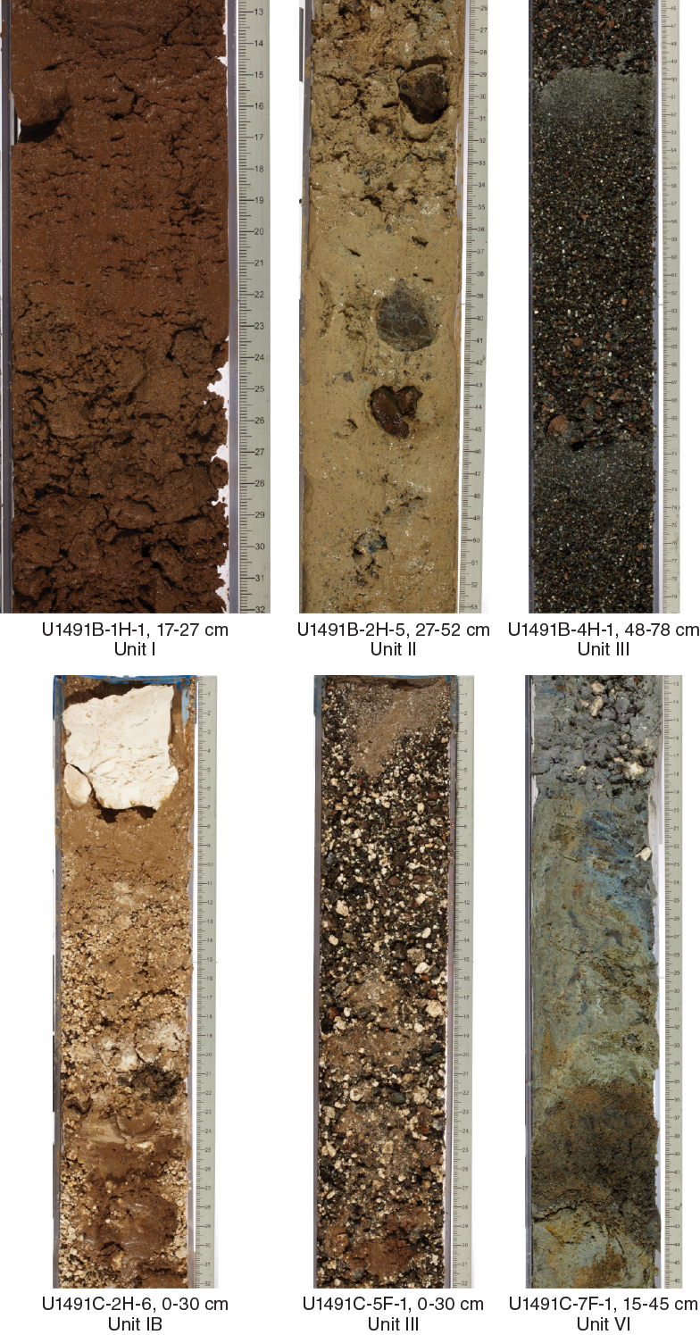
Figure F7. Lithostratigraphic units.
Table T2. Lithostratigraphic units, Hole U1491B. Download table in CSV format.
Unit I
Unit I is 5.13 m thick and consists of red-brown clay-rich pelagic mud with mudstone clasts (~11%). There is one light brown burrow (?) in Section 1H-3, 26–36 cm. Mudstone clasts dominate the upper part of the unit (Section 1H-1, 0–95 cm); in Section 2H-1, 49 cm, granule- to pebble-sized carbonate dominates. In Sections 2H-1, 95 cm, to 2H-1, 110 cm, there is a 15 cm thick zone of almost pure carbonate, with large pebble-sized clasts in a matrix of smaller clasts and grains. Deeper carbonate and mudstone clasts are present in subequal proportions to Section 2H-1, 142 cm. In Section 2H-2, 0–26 cm, the uppermost part of Unit II consists largely of soupy carbonate mud with large carbonate clasts (as large as 5 cm). The carbonate layer grades with a coring-disturbed contact into the gray-green serpentinite mud of Unit II. The carbonates are fossiliferous shallow-water reef fragments. The lower part of Unit I is similar to the carbonate-rich lower part of Subunit IB in Hole U1491C. Note that some of the serpentinite mud from Unit II was drawn upward into the top of Unit II (to about Section 2H-2, 13 cm) by coring suction (flow-in).
Unit II
Unit II is 11.23 m thick and consists of gray-green pebbly serpentinite mud with lithic clasts. The dominant clasts are pebble-sized serpentinized ultramafic rocks (~21%), and the subdominant clasts are coarse sand– to pebble-sized fragments (~5%) of mudstone or highly altered volcanic rock. The serpentinite clay matrix is mottled in some intervals, with clots of paler green material interspersed in the gray-green matrix and, in some places, with black patches and dark halos around some clasts. The matrix appears soft and disturbed by coring in the upper part of Section 2H-2. Coring disturbance is apparent in Sections 2H-5 through 2H-CC where the matrix necks in and becomes softer. Starting in Section 3H-1, the matrix is more bluish gray than greenish gray and contains more lithologically diverse fragments of the coarse sand– to pebble-sized rocks. It also contains carbonate fragments (e.g., in Section 3H-1, 70–72 cm). In the last section of this unit, the serpentinite mud shows flow-in features on the right side of the archive half and the serpentinite matrix muds appear disturbed in some areas showing isoclinal folding with axes perpendicular to the length of the section. There are a few fragments of breccia in the unit.
Unit III
Unit III is 3.06 m thick and consists of three grayish to olive-green, normally bedded, well-sorted sections of drilling cuttings. Unit III is divided into three intervals within which this graded sequence is repeated. The upper two of these intervals both have fine-sand tops grading into coarse pebbly bases. Both consist of the same grain-size distribution. All fragments comprise dominant angular to subrounded pieces of dark gray to red-brown serpentinized ultramafic rock with subdominant brown siltstone and white carbonate. All three graded sections contain the same three lithologies in the about the same proportions. The lowermost of the three graded sections ranges in size from fine sand to 3 cm in diameter subangular and angular pebbles. In Section 4H-3, 47–51 cm, there is an interval of serpentinite mud similar to the gray mud at the base of Unit II.
The current interpretation of these sequences is that the drill bit encountered a layer of matrix-supported, coarse serpentinized ultramafic rocks and carbonate (possibly similar to that in Sections 2H-1 and 2H-2) after coring Section 3H-3. The APC cores taken at this site were full-length APC cores, so the small recovery obtained in Core 3H necessitated drilling down to establish the next depth target for the APC shot for Core 4H. Flushing the hole to assist in drilling to the necessary depth distributed the ground-up rock fragments in a normally sorted layer in the hole. When setting up to shoot APC Core 4H (now a graded sequence of ground-up and fall-in material from the rock and serpentinite mud and carbonate layers), the heave of the drill string disturbed the uppermost part of the cuttings and redistributed them into the two shorter graded sequences with similar grain-size distribution in Section 4H-1. The material present in the lower part of Core 4H and all of Core 5H represents the original fall-in cuttings from the interval below the base of Section 3H-3.
Hole U1491C
Hole U1491C contains six units that comprise 24.57 m of core (Figures F5, F7; Table T3). Unit I is further divided into Subunits IA, IB, and IC.
Table T3. Lithostratigraphic units, Hole U1491C. Download table in CSV format.
Unit I
Subunit IA
Subunit IA is 7.51 m thick and consists of red-brown clay-rich pelagic mud with mudstone. In Section 2H-4, 76–96 cm, there is an about 45° contact between the upper brown, vitric silty clay and a lower grayish brown serpentinite mud. The lower part of this section was removed as whole rounds. The grayish brown serpentinite mud was observed as clumps in Section 2H-5, 1–6.5 cm.
Note that in Section 2H-5, 57–122 cm, the core photos give the impression of biscuits (commonly observed in semilithified clays during XCB or rotary core barrel [RCB] coring); however, in this case they are not drilling disturbance, but rather impressions from spatulas used to separate the working and archive section halves of the cores. At Section 2H-5, 122–125 cm, the brown sediment becomes soupy and contains about 4% carbonate and about 2% sand. The matrix is well-sorted vitric silt and claystone, and in Section 2H-5, 143–140 cm, a large (8 cm), angular cobble of carbonate indicates the transition to Subunit IB. This carbonate clast is likely a fossiliferous fragment of shallow-water reef material but also contains a gastropod fossil in Section 2H-5, 136.2–136.8 cm.
Subunit 1B
Subunit IB is 3.02 m thick and consists of pink, clayey, pebble-sized, angular to subangular carbonate clasts (~37%) and subangular very coarse sand–sized serpentinized ultramafic clasts and granule-sized carbonate clasts (~22%) mixed in with some clumps of brown mud/claystone. From Section 3F-1, 45 cm (48 cm thick), to the base of the unit (Section 3F-1, 93 cm) is a complex mix of coarser and finer grained mudstone and carbonate sand- to pebble-sized fragments. The finer grained areas have a clay-sized matrix that is generally reddish brown (pelagic sediment and clay derived from mudstone) to pale brown carbonate silt and sand that may include serpentinite mud in places (greenish tinge). Coarser grained areas are typically richer in granule- to pebble-sized carbonate clasts. From about Section 3F-1, 63–93 cm, there is a more normally graded sequence consisting dominantly of carbonate sand and gravel, with black lithic clasts that appear to be highly serpentinized ultramafic rocks. It changes color downsection from pinkish to black and white, reflecting a decrease in clay content. Single large (4–6 cm across) angular carbonate clasts containing reef debris occur in Sections 2H-6, 1–7 cm; 2H-CC, 1–6 cm; and 3F-1, 41–45 cm within carbonate-rich zones (see smear slide description in Petrology). The lower contact with Subunit IC is sharp and essentially horizontal.
Subunit IC
Subunit IC is 0.85 m thick and consists of brown matrix-supported, polymict-conglomeritic sediment with dominant pebble- to cobble-sized angular mudstone clasts (~28%) and subdominant subangular, granule- to pebble-sized, serpentinized ultramafic clasts (~8%). A composite clast (Figure F8) made of semi-indurated brown mudstone and highly altered serpentinized ultramafic rocks with thick black (Mn oxide?) encrustations were recovered in Section 3F-1, 142–151 cm.
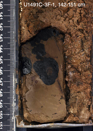
Figure F8. Composite clast.
Unit II
Unit II is 3.1 m thick and consists of greenish gray to reddish brown serpentinite pebbly mud with pebble- to cobble-sized clasts of serpentinized ultramafic rock (~10% clasts) and sparse (<2%) pebble-sized clasts of breccia with carbonate cement. Some ultramafic clasts exhibit red weathering with black (Mn-rich?) crusts (Figure F9) in Sections 3F-2, 77–91 cm; 3F-3, 6–11 cm; 3F-3, 48–54 cm; 3F-4, 20–29; and 3F-4, 37–48 cm. These clasts commonly contain relict primary olivine and orthopyroxene (see Petrology). Someone removed the clasts from the archive section halves of Sections 3F-3 and 3F-4 shortly after recovery (the core photographs show these missing clasts), and the clasts were not returned, so they are unavailable for sampling. The matrix is gray-green serpentinite mud mottled with dark patches.
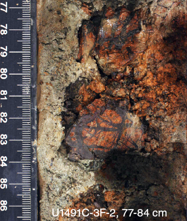
Figure F9. Ultramafic clast.
Unit III
Unit III is 2.67 m thick and consists of three layers with normally graded bedding. The upper layer, in Section 4F-1, 0–20 cm, grades rapidly from fine sand with faint horizontal layering at the top to coarse sand and pebbles at the base. This layer contains several large (3–5 cm) clasts of mudstone at the middle and bottom of the layer. The upper graded layer is underlain by a matrix-supported coarse sand– to pebble-sized, polymict layer in Section 4F-1, 20–34 cm. The matrix is serpentinite mud, and both the upper and lower contacts of this polymict material have irregular surfaces with about 3 cm of relief on each contact.
The middle graded layer extends from Section 4F-1, 34 cm, to Section 4F-CC, 10 cm. The base of this layer is polymict clast-supported gravel of granule- to pebble-sized (as large as 2 cm) subangular to subrounded clasts of carbonate (reef material?), serpentinized ultramafic rock, and mudstone that grade downward from a fine sand of similar composition. Within the middle graded layer are two patches of serpentinite mud–supported, polymict coarse sand to pebbles, similar to that in Section 4F-1, 20–34 cm. This middle graded layer also contains two 4–5 cm long clasts. One is ophicarbonate breccia (fragments of serpentinized ultramafic rock cemented by carbonate) in Section 4F-1, 93–98 cm; the other (Section 4F-1, 102.5–106.5 cm) is red-brown serpentinized ultramafic rock crosscut by numerous black serpentine veins; it has a coating of black serpentine at one end (Section 4F-1, 102.5–106.5 cm). This clast is similar to those removed from the archive section halves of Sections 3F-3 and 3F-4. In Section 4F-1, 35–119 cm, there are small (coarse sand– to pebble-sized) subangular to subrounded clasts of this same red-brown serpentinized ultramafic rock scattered throughout the unit.
The lowermost graded layer begins in Section 5F-1, 0 cm, and continues to the base of the unit in Section 5F-2, 8 cm. It is very similar to the middle graded layer and coarsens downward very gradually from coarse sand in the upper 40 cm to a base of clast-supported polymict breccia–conglomerate with granule- to pebble-sized (as large as 2 cm) clasts of carbonate (coral) and serpentinized ultramafic rock.
Unit IV
Unit IV is 2.19 m thick and consists of greenish gray serpentinite pebbly mud with black patchy mottling and granule- to pebble-sized, angular to subangular serpentinized ultramafic rock clasts (~19%). In the patches of black mottling, the serpentinized ultramafic clasts are also black. In Section 5F-2, 42–45 cm, are two subangular, serpentinized ultramafic clasts; one is a breccia and the other is similar to the serpentinized ultramafic clasts with red-brown cores and black serpentine veins that were removed from the archive section halves of Sections 3F-3 and 3F-4. In Section 6F-1, 0–27 cm, a normally graded interval consists of subangular to subrounded coarse sand– to pebble-sized fragments of serpentinized ultramafic and white carbonate, with small patches of light gray to greenish gray serpentinite mud (especially in Sections 6F-1, 5–8 cm; 6F-1, 16–18 cm; and 6F-1, 22.5–23.5 cm). This interval is poorly consolidated and likely fall-in debris from higher up in the hole.
Unit V
Unit V is 1.18 m thick and consists of three sequences of normally graded polymict granule- to pebble-sized clasts of serpentinized ultramafic rocks (~23%), carbonates (~47%), and rare mudstones. In Section 6F-1, 27–59 cm, there is a serpentinite mud (light gray to greenish gray)–supported interval of pebble-sized, subrounded carbonate clasts (40%), pebble-sized angular to subangular serpentinized ultramafic clasts (20%), and mixed clay- to sand-sized grains. In Sections 6F-1, 58 cm, to 6F-2, 30 cm, there is an interval of poorly consolidated sand- to pebble-sized, subangular to subrounded fragments of serpentinized ultramafic and white carbonate. In Section 6F-1, 59–63 cm, the fragments grade from fine sand to coarse sand, and in Section 6F-1, 63–68 cm, grain size rapidly increases to about 1 cm and slowly increases to slightly over 1 cm throughout the rest of the unit, which ends at Section 6F-2, 35 cm. The graded bedding sequences in this unit are likely the result of heave on the drill string as coring progressed through this part of the hole.
Unit VI
Unit VI is 4.02 m thick and consists of greenish to bluish gray serpentinite pebbly mud with coarse sand– to pebble-sized subangular to subrounded serpentinized ultramafic clasts (~7%) and carbonate rock clasts (~6%). This material is similar to that of Unit II in Section 3F-CC.
Drilling fall-in material is seen in Sections 7F-1, 0–25 cm, 8F-1, 0–37 cm, and 9X-CC, 0–6 cm. The fall-in material typically comprises white sandy mud with granule- to pebble-sized clasts of mudstone, serpentinized ultramafic rocks, and carbonates (described on the visual core descriptions as clast-supported polymict breccia–conglomerates although it is not lithified).
Petrology
Serpentinite mud matrix
The serpentinite mud matrix consists of clay- to silt-sized serpentine minerals and other fragments of variably serpentinized ultramafic rocks with accessory brucite, magnetite, chromian spinel, calcite, aragonite, zeolite, and other unidentifiable phases. It is inferred from the mud volcano setting that the majority of the mud is finely ground fault gouge. The serpentinite mud contains granule- to cobble-sized lithic clasts. Detailed petrography of the representative rock clasts and their thin sections are described in Serpentinized ultramafic clasts.
Hole U1491B
Two smear slides from Unit II were examined (Samples 366-U1491B-3H-2, 64 cm, and 3H-3, 82 cm). They consist mainly of clay- to silt-sized serpentines (70%–90%). Euhedral to subhedral carbonate crystals 10–50 µm in size are common (as much as ~30%) in Sample 3H-2, 64 cm (Figure F10). Reddish brown chromian spinel (<50 µm) and black magnetite (<10 µm) were also observed as accessory minerals.
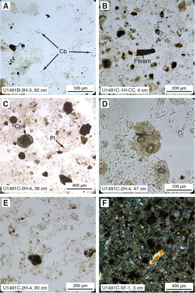
Figure F10. Smear slide images.
Hole U1491C
One smear slide from Subunit IA (Sample 366-U1491C-1H-CC, 4 cm) and three from Subunit IB (Samples 2H-4, 38 cm; 2H-4, 47 cm; and 2H-4, 80 cm) were examined. Clay is dominant (63%–80%) in all four samples. Trace amounts of volcaniclastic glass, plagioclase, clinopyroxene crystals, and pumice were observed (Figure F10). In Subunit IA, a few foraminifers and sponge spicules were also observed (Sample 1H-CC, 4 cm). Volcanic glass is relatively abundant (~3%) in Sample 1H-CC, 4 cm. Biotite was observed in Sample 2H-4, 47 cm. Various volcanic lithic fragments occur in every smear slide, which may cause the observed variable colors of different lithologic units. For example, the lithic clast in Sample 2H-4, 38 cm, is rounded and opaque rich (~10%), whereas the clast (~17% opaque rich) in the lower layer (Sample 2H-4, 47 cm) is transparent. This difference is consistent with the slightly darker color in the upper layer. Zeolite (phillipsite suggested by cruciform twinning) is ubiquitous (over 7%) in the matrix of Sample 2H-4, 80 cm, and an embayed structure of zeolite implies partial dissolution. One smear slide (Sample 5F-1, 3 cm) from the top of the second graded interval of Unit III shows that carbonate is dominant (~60%) in the silty to sandy matrix, with ~40% serpentine/serpentinite sand. Three smear slides from Unit VI (Samples 7F-1, 22 cm; 7F-1, 40 cm; and 7F-1, 51 cm) display sand- to clay-sized serpentine as dominant (>98%) in the matrix, with accessory magnetite ± carbonate minerals.
Carbonate breccias (ophicarbonates)
Several clasts of serpentinized ultramafic breccia cemented with carbonate were recovered from the shallowest part of Holes U1491B and U1491C. These clasts are composed of various sizes of angular serpentinized ultramafic fragments (100 µm to several centimeters) cemented by a fine-grained carbonate matrix. Sulfide minerals, tentatively identified as pyrite or pyrrhotite, were found throughout the core.
Hole U1491B
Sample 366-U1491B-2H-5, 85–88 cm (Thin Section [TS] 3), is breccia made of serpentinite clasts (about 100% serpentinization) embedded in a carbonate matrix (representing about 50% of the sample). The carbonate matrix mainly consists of calcite associated with radial aragonite and embeds various sizes of clasts (10 µm to 1 mm) composed of interpenetrating serpentine. A few small relics of fibrous serpentine or bastite were also observed within the carbonate matrix (Figure F11A).
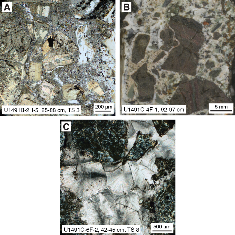
Figure F11. Carbonate breccia.
Hole U1491C
Two clasts of serpentinized ultramafic breccia cemented with carbonate were recovered in a gravel interval (Samples 366-U1491C-4F-1, 92–97 cm [TS 7], and 6F-2, 42–45 cm [TS 8]). In each sample, the carbonate cement is made of radial aragonite with rare crystals of calcite. Sample 4F-1, 92–97 cm (Figure F11A–F11C), is characterized by a high proportion of carbonate cement (as much as 70%). It penetrates the serpentinite mud matrix in which the serpentinized peridotite clasts are embedded. The clasts have finely recrystallized in interpenetrative lamellae of serpentine. In Sample 6F-2, 42–45 cm, the serpentinite clasts are composed of serpentine with pseudomorphic mesh and bastite textures crosscut by fibrous serpentine veins, and the carbonate matrix occupies about 40% of the sample. A few small magnetite grains (<10 µm) are disseminated into mesh textures.
Serpentinized ultramafic clasts
Serpentinized ultramafic clasts are typically pebble to cobble sized (as large as 7 cm). They are mainly composed of a dark blue serpentine matrix, white millimeter-scale bastites, and reddish brown chromian spinel. The ultramafic clasts are occasionally crosscut by one or several blue, white, or brown fibrous veins. These veins often crystallize in conjugated fractures and can display crack-seal-like textures.
Hole U1491B
Three serpentinized harzburgite clasts embedded in serpentinite mud were petrographically examined (Samples 366-U1491B-2H-2, 69–89 cm [TS 2], 3H-2, 10–15 cm [TS 4], and 5H-CC, 1–5 cm [TS 5]). Sample 2H-2, 69–89 cm (Figure F12A), is an ultramafic clast (about 100% serpentinization) preserving rare relics of olivine and orthopyroxene. Olivine and orthopyroxene are replaced by pseudomorphic serpentine displaying mesh and bastite textures, respectively. The olivine is too altered to decipher primary grains or grain size. Bastite pseudomorphs indicate primary orthopyroxene as long as 11 mm by 4 mm wide, with an average grain size of about 4 mm. Some of the smaller orthopyroxenes have fish shapes, indicating a porphyroclastic texture. Spinels average about 0.2 mm, with interstitial holly leaf shapes. The clast is crosscut by thick veins of fibrous serpentine (about 100 µm wide).
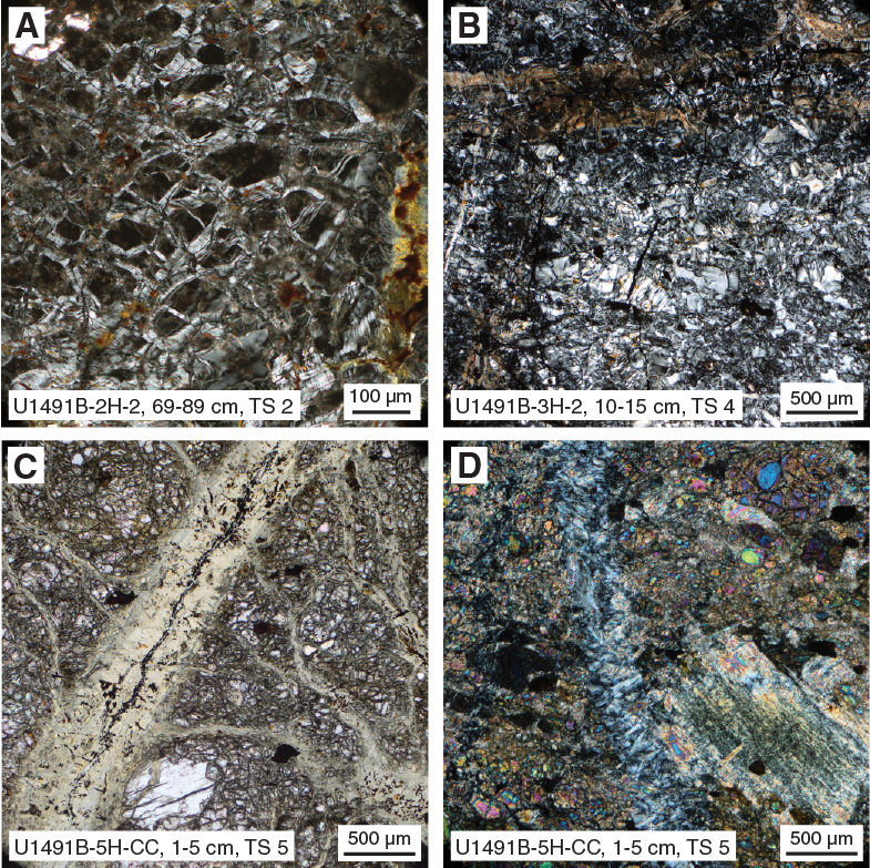
Figure F12. Serpentinized harzburgite clasts.
Sample 3H-2, 10–15 cm (Figure F12B), is serpentinized harzburgite. The primary mode is about 70% olivine, 30% orthopyroxene, and 1% chromian spinel (~100 µm wide). Orthopyroxene porphyroclasts are 3 to 4 mm long by 0.6 to 1.2 mm wide. Many porphyroclasts have fish shapes with undulatory extinction; some have severe kink folds. The primary texture was porphyroclastic. Veins are about 500 µm wide and contain carbonate and brownish fibrous serpentine associated with magnetite strings. The ultramafic components display interpenetrating and bastite textures replacing the primary olivine and orthopyroxene.
Sample 5H-CC, 1–5 cm (Figure F12C), is serpentinized harzburgite (about 50% serpentinization) displaying two domains with various degrees of serpentinization. The first domain preserves small round olivines about 10 to 50 µm wide and large orthopyroxenes approximately 500 µm wide. Olivine grains are surrounded by small (about 10 µm wide) serpentine veins. Olivine has a strongly foliated fabric, with relict grains from 0.8 mm × 0.2 mm to 0.4 mm × 0.1 mm in size, aligned in a foliation. Spinels are flattened in foliation plane as well. Porphyroclasts of orthopyroxene are as long as 2.4 mm. The inferred primary texture is equigranular tabular (foliated equigranular).
In the second domain (Figure F12D), primary minerals are fully replaced by pseudomorphic serpentine with mesh and bastite textures. Both domains are crosscut by thick veins of serpentine from 100 to 500 µm wide. Two different types of veins were observed: V1 is a serpentine vein with greenish footages and pseudomorphic mesh textures associated with thin strings of magnetite, and V2 is composed of serpentine with interpenetrating textures. V2 veins crosscut V1 veins; V2 veining must thus have occurred subsequent to V1 veining.
Hole U1491C
Two thin sections of serpentinized ultramafic clasts were examined (Samples 366-U1491C-3F-3, 50–53 cm [TS 6], and 6F-2, 42–45 cm [TS 8]).
Sample 3F-3, 50–53 cm, displays two domains: (1) a serpentinite domain composed of interpenetrative lamellae of serpentine crosscut by large crack-seal veins about 500 µm wide and (2) a domain composed of orthopyroxene and olivine with reddish alteration textures. The extent of alteration is about 80%. Altered olivine and orthopyroxene are crosscut by serpentine veins with interpenetrative textures. Highly deformed orthopyroxene porphyroclasts are elongate (~2 mm long × 1.1 mm wide) and have kink folds and undulatory extinction. There may be some relict clinopyroxene inclusions in bastite. The primary texture was likely porphyroclastic.
Sample 6F-2, 42–45 cm, is brecciated serpentinite with carbonate veins of radial aragonite and calcite. This sample also contains euhedral crystals of a very fine grained sulfide mineral provisionally identified as pyrrhotite (Figure F13). Abundant sulfide grains are primarily contained in carbonate veins along contacts with the serpentinized peridotite domains (Figure F14).
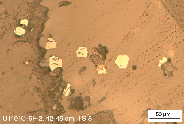
Figure F13. Putative pyrrhotite or pyrite grains.
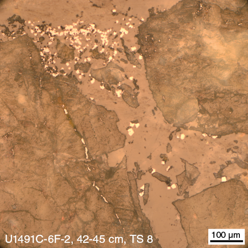
Figure F14. Very fine grained sulfide grains.
Structure
Brittle deformation structures were observed in a few clasts from Holes U1491B and U1491C, particularly in Cores 366-U1491B-2H through 3H and 366-U1491C-3F through 6F (Figures F15, F16). Two main types of breccia were distinguished: (1) carbonated breccia and (2) serpentinized harzburgite breccia. These two types are equally represented in the breccia population recovered from the two holes and were observed within all of the lithostratigraphic units described above in Lithostratigraphy.
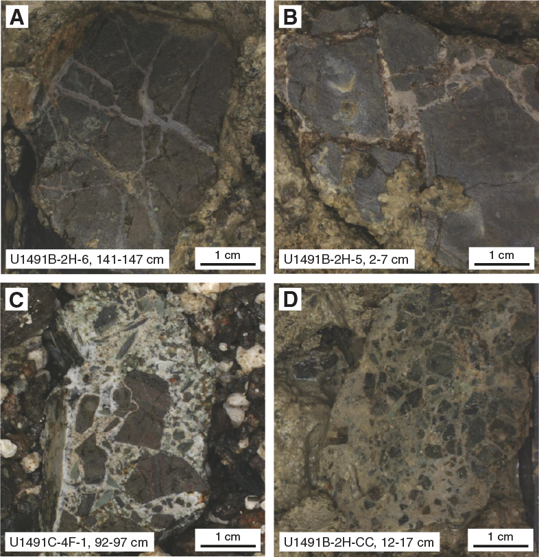
Figure F15. Carbonate breccia.
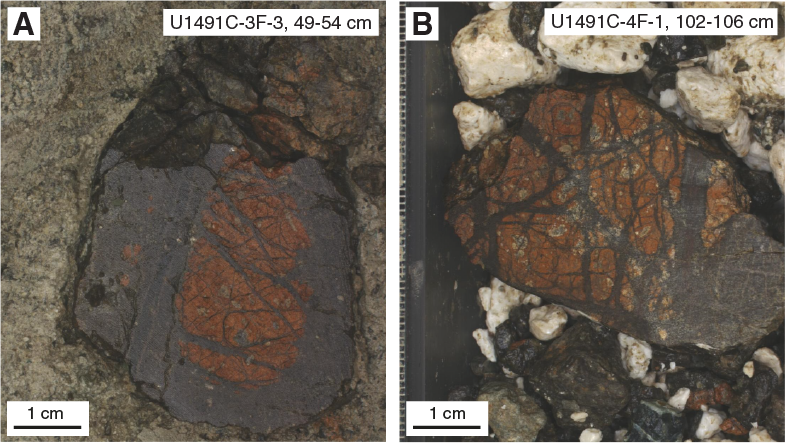
Figure F16. Serpentinized harzburgite clasts.
Carbonate breccia clasts are characterized by different degrees of brecciation, from isolated, single, filled fractures crosscutting ultramafic clasts to a dominant carbonate matrix (>50% of the clasts) enclosing millimeter-sized subangular to subrounded pieces of ultramafic clasts and serpentine vein fragments. The veins and matrix cement are mainly composed of carbonate and serpentine. At microscale, the breccia consists of a carbonate matrix and various lithic clasts. The clasts are mainly massive serpentinized harzburgite (100% altered). The serpentinite clasts display pseudomorphic and nonpseudomorphic (interpenetrating) textures. The matrix is composed of carbonate embedding serpentinite matrix mud (Samples 366-U1491B-2H-5, 85–88 cm, and 366-U1491C-4F-1, 92–97 cm, and 6F-2, 42–45 cm) (Figure F17).
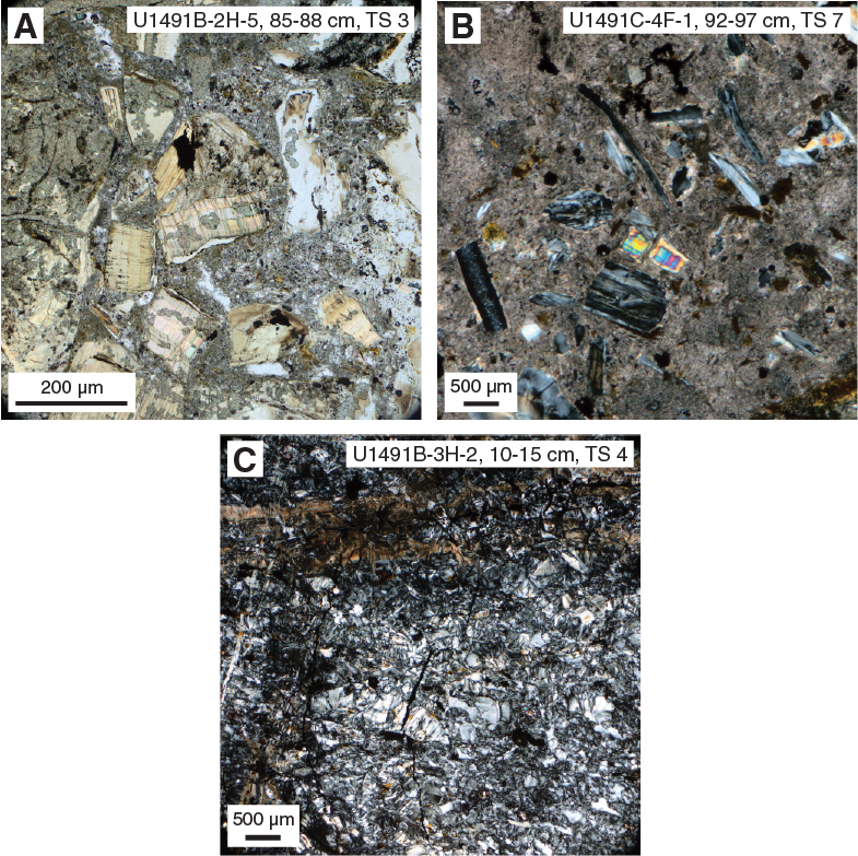
Figure F17. Serpentinite breccia.
These different degrees of brecciation could be related to different degrees of deformation, from distinct fracturing to well-developed fault breccia. No main orientation of the fault networks or of the embedded clasts can be distinguished.
Some serpentinized harzburgite clasts (e.g., Section 366-U1491C-3F-2, 77–90 cm) are subrounded and as much as ten centimeters in diameter. These clasts are nodule-like features with a heavily altered interior (harzburgite) that is red-brown and crosscut by dark brown veins of the same material as the dark brown outer layer (Figure F16). The vein network is composed of veins with variable widths and irregular orientation. The breccia microstructure is characterized by massive serpentinized harzburgite (100% altered). The olivine domain is replaced by nonpseudomorphic serpentine displaying interpenetrating textures. The orthopyroxene domain is replaced by serpentine with bastite texture. The serpentine textures are crosscut by microveins composed of brownish and fibrous serpentine associated with carbonate and magnetite. Few late fibrous small (<10 µm wide) serpentine veins were observed (Sample 366-U1491B-3H-2, 10–15 cm) (Figure F17).
In Sample 5H-CC, 1–5 cm (Figure F12C), the matrix is crosscut by thick veins of serpentine 100 to 500 µm wide. Thinner veins of proto-serpentine with crack-seal features (Andreani et al., 2004; Gratier and Gueydan, 2007) were observed at the center of those thick veins. Two additional thin sections (49 and 50) were made in the two orthogonal planes to the original thin section (5) (Figure F18) to better analyze the thin vein network and try to identify the opening kinetics of the fractures and their sealing mechanism.
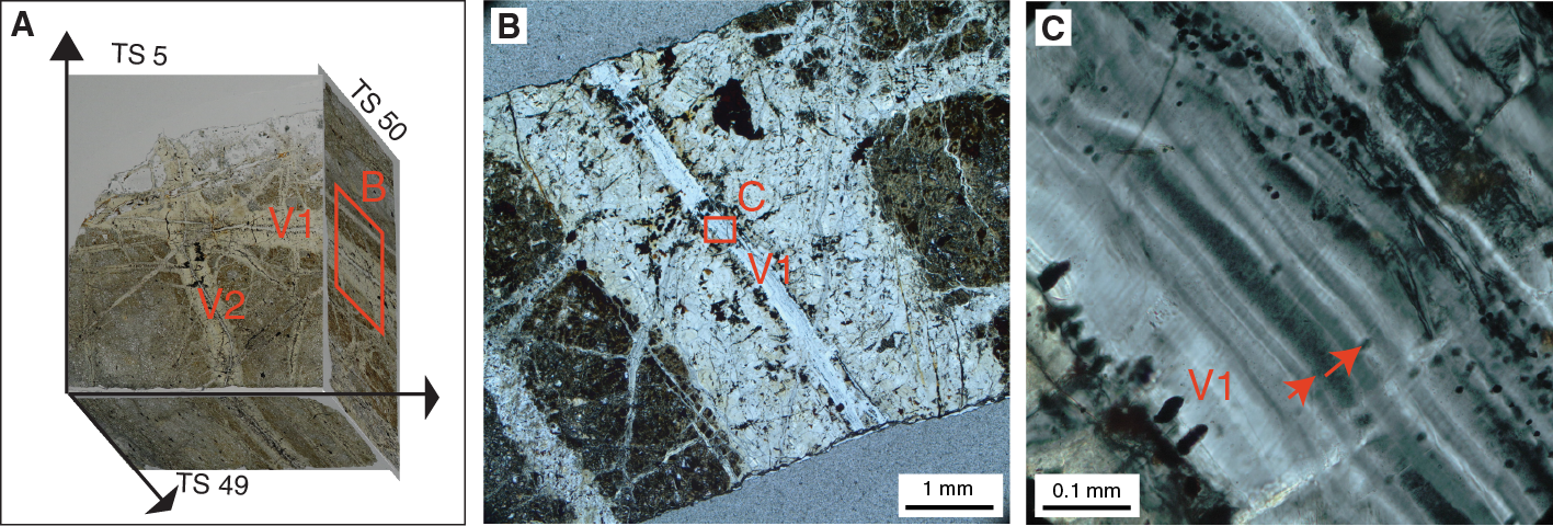
Figure F18. Proto-serpentine veins.
The internal structure of these veins was only revealed under crossed polars. Vein V1 internal fillings are banded, with 1–4 µm bands subparallel to the vein walls. The incremental growth is unidirectional, with wall inclusions at the base of the growing system. The grain size of serpentine is not visible, and the mineral growing direction of Vein V2 cannot be described at this stage. It requires additional chemical and imaging analyses (scanning electron microscope and transmission electron microscopy).
Lithostratigraphy, petrology, and structure summary
Site U1491 is located on the flank of Yinazao Seamount near the base of a slight topographic valley (Figure F6). The nature of the unconsolidated units recovered in Holes U1491A–U1491C is consistent with the interpretation that these units represent serpentinite mudflows, the deepest of which tapped a source of carbonate clasts and serpentinized ultramafic rocks that were possibly far less matrix supported by serpentinite mud than those observed elsewhere. The source of the carbonate gravels is possibly an underlying subducted Cretaceous seamount. Typically, mixed pelagic muds containing a variety of clastic materials are found at the tops of the holes. Beneath the pelagic sediments, sequences of normally graded carbonate-dominant sand- to gravel-sized unlithified units and serpentinite muds containing serpentinized ultramafic and occasionally carbonate (reef material?) clasts are found. Generally, these different lithostratigraphic units have distinct contact interfaces, supporting the hypothesis that the deposits result from sporadically energetic downslope flows of serpentinite mud.
Rock and sediment geochemistry
Elemental abundances for Site U1491 samples selected by the shipboard scientific party were determined using inductively coupled plasma–atomic emission spectroscopy (ICP-AES) and portable X-ray fluorescence spectrometer (pXRF) analysis (Table T4). pXRF calibration curves are provided in Figure F2 in Johnston et al. (2018). The examined samples included serpentinite muds and serpentinized ultramafic rocks (harzburgites and/or dunites). A full discussion of Expedition 366 rock, mudflow, and sediment data is found in Sediment and rock chemistry in the Expedition 366 summary chapter (Fryer et al., 2018b).
Table T4. ICP and pXRF data. Download table in CSV format.
Fluid geochemistry
Headspace hydrocarbon gas and H2 analyses were performed on samples from Holes U1491B and U1491C as part of standard shipboard safety monitoring procedures and to track the occurrence of hydrocarbon volatiles through the cores. One to two samples per core were collected (typically at the top of Section 3) from Cores 366-U1491B-1H through 5H and 366-U1491C-1H through 9X. Ten whole-round samples were collected for interstitial water analyses from the same cores (typically at the bottom of Sections 2 and 4 above the headspace hydrocarbon gas sample). Interstitial water samples were typically 10 cm long. The volume of recovered interstitial water was ~30 to 86 mL. Headspace gas and interstitial water samples were collected and analyzed as described in Fluid geochemistry in the Expedition 366 methods chapter (Fryer et al., 2018a).
Headspace analysis of H2, CO, and CH4
Dissolved H2, CO, and CH4 in the unconsolidated materials were measured in several intervals in Holes U1491B and U1491C (Table T5; Figure F19). Although CO concentrations were below detection limits in all samples from Holes U1491B and U1491C, H2 and CH4 were detected by gas chromatograph (GC)–helium ionization detector (HID) and GC–flame ionization detector (FID) analyses, respectively. H2 concentrations generally increase with depth in both holes. The observed range of H2 concentrations is similar to that encountered in shallow seafloor sediments. CH4 was also measured via GC-FID analysis, with values ranging between 1.5 and 2.2 ppmv. These values are similar to the CH4 concentration of ambient air in the laboratory, thus equivalent to the natural background.
Table T5. Dissolved H2, CH4, and CO. Download table in CSV format.
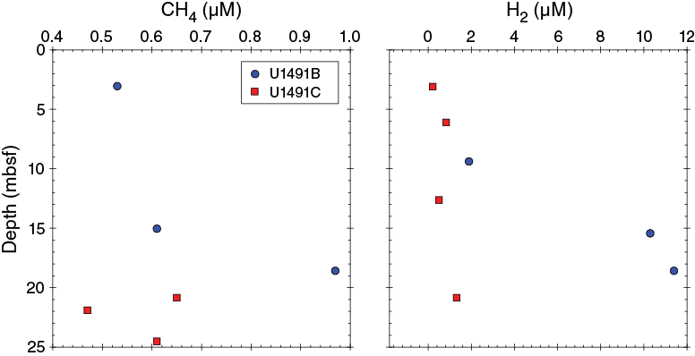
Figure F19. H2 and methane.
Electrochemical sensing of H2 and H2S
H2 and acid volatile sulfide (AVS) concentrations were measured using an electrochemical H2 probe (H2-NR, Unisense, Denmark) and an H2S probe (H2S-NR, Unisense, Denmark), respectively. H2 and AVS concentrations were below detection limits in all samples from Holes U1491B and U1491C.
Interstitial water
The salinity, pH, alkalinity, and chloride contents of the 10 interstitial water samples collected from Site U1491 were measured immediately after sampling. Samples were analyzed for ammonium, hydrogen sulfide, and phosphate by UV-vis spectrophotometry and for Mg, K, Na, bromide, chloride, and sulfate by ion chromatography (IC). Major (Mg, K, and Ca) and trace (Li, B, Mn, Fe, Sr, and Ba) cations were measured using the shipboard Teledyne Leeman Labs Prodigy ICP-AES instrument. The wavelengths examined for these elements are listed in Table T1 in the Expedition 366 methods chapter (Fryer et al., 2018a). Dissolved inorganic carbon (DIC) and dissolved organic carbon (DOC) were measured with the OI Analytical Aurora 1030C total organic carbon (TOC) analyzer. For hydrogen sulfide, we initially assumed that it would stay in solution because of the pH of the interstitial water samples, but when measured by spectrophotometry, there was none detected. However, hydrogen sulfide was precipitated for subsequent shore-based analysis of the sulfur isotopic composition. Concentrations of H2S will also be measured on these samples. These shore-based samples were preserved by adding Cd(NO3)2, which forms CdS in the presence of H2S. Visible precipitation and thus the presence of sulfide was only observed in a sample from Section 366-U1491B-2H-2. No other Site U1491 samples showed visible CdS precipitation. Furthermore, sulfide values should be low (<2 mM) given the similarity in the chlorinity and chloride concentrations. The cations analyzed by IC and the major cations analyzed by ICP-AES overlap, and comparisons between these data indicate the instruments produced largely similar results for Mg, K, and Ca but less similar results for Na (Figure F20). We use the IC Na results and the ICP-AES Ca, Mg, and K results in the figures in this section, as described in Fluid geochemistry in the Expedition 366 methods chapter (Fryer et al., 2018a).
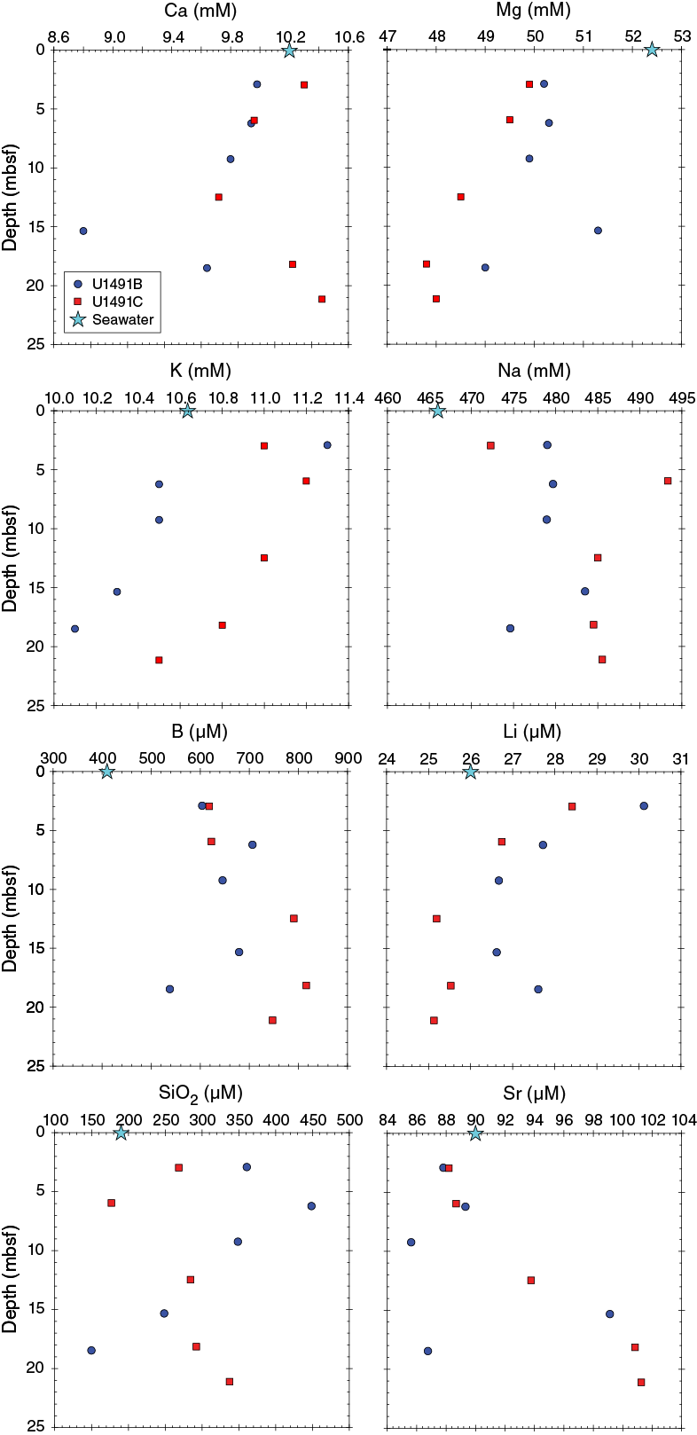
Figure F20. Major and minor cations.
The chemical composition of the interstitial water data is listed as a function of depth in Table T6. Top depth (on the core depth below seafloor [CSF-A] scale) plus half of the length of the whole round was used in Figures F19, F20, F21, and F23. Methods (ICP-AES, IC, spectrometer, and titration) are listed, including the wavelength used for elements analyzed by ICP-AES.
Table T6. Interstitial water analyses. Download table in CSV format.
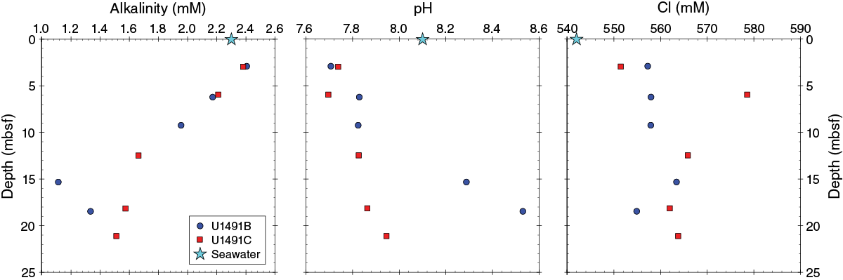
Figure F21. pH, alkalinity, and chloride.
Salinity, pH, alkalinity, and chloride
The salinity of Site U1491 interstitial water samples is typically around that of seawater, ranging from 34 to 35 in most samples from Holes U1491B and U1491C (Table T6). However, one sample at ~6 mbsf in each hole has higher salinity than seawater (42 for Hole U1491B and 37 for Hole U1491C). The reason for these higher values is unclear.
pH ranges from 7.71 to 8.53 in Hole U1491B and from 7.70 to 7.95 in Hole U1491C. Alkalinity ranges from 1.11 to 2.41 mM in Hole U1491B and from 1.51 to 2.38 mM in Hole U1491C (Table T6; Figure F21). Most of these values are less than those of seawater and are markedly lower than those observed in summit springs on other Mariana forearc seamounts (e.g., Mottl et al., 2004; Hulme et al., 2010). Alkalinity decreases downhole, whereas pH increases. The slight elevations in pH may relate to some minor ongoing serpentinite formation in Site U1491 unconsolidated materials, but the overall signal is dominated by seawater. Chloride ranges from 555 to 563 mM in Hole U1491B and from 551 to 579 mM in Hole U1491C. These values are within the analytical precision for seawater.
Ammonium, phosphate, sulfate, and bromide
Measured ammonium (NH4+) concentrations range from 39.3 to 52.6 µM in Hole U1491B and from 36.6 to 44.6 µM in Hole U1491C (Table T6; Figure F22). These concentrations are elevated above typical seawater values (submicromolar) and similar to previous data (e.g., ODP Sites 783 and 784 on Torishima Seamount, an inactive serpentinite seamount in the Izu-Bonin forearc [Mottl, 1992]). These values are significantly lower than those measured at active mud volcanoes like Conical Seamount, which reaches concentrations of up to 200 µM within the upper 20 m (Mottl, 1992). Phosphate ranges from below the detection limit to 1.9 µM in Hole U1491B and from below the detection limit to 1.7 µM in Hole U1491C. Phosphate ranges from 0.2 to 0.4 µM at Conical and South Chamorro Seamounts, respectively. Measured ammonium concentrations decrease slightly downhole in Holes U1491B and U1491C, whereas phosphate concentrations decrease downhole in Hole U1491B but increase downhole from the first sampled depth that was much lower than bottom seawater in Hole U1491C.

Figure F22. Ammonium, phosphate, bromide, and sulfate.
Most sulfate concentrations are enriched slightly over seawater values (28 mM), with the exception of the deepest sample collected from Hole U1941B (e.g., 28 to 29.5 mM for most samples and ~27 mM for the sample from 18.5 mbsf). Measured values are within typical seawater ranges. Bromide concentrations are higher than seawater (0.83 mM) and increase with depth, ranging from 0.86 to 0.89 mM in Hole U1491C and 0.87 to 0.89 mM in Hole U1491B.
Major and trace cations
Ca concentrations are near seawater values (10.2 mM), ranging from 9.98 to 9.64 mM in Hole U1491B and from 9.72 to 10.42 mM in Hole U1491C (Figure F20). Ca concentrations decrease downhole in Hole U1491B. Mg concentrations are overall slightly lower than that of seawater (52.4 mM), ranging from 49.0 to 51.3 mM in Hole U1491B and 47.8 to 49.9 mM in Hole U1491C, with a subtle decrease in concentration downhole (Figure F20). K concentrations also decrease downhole at values slightly higher than that of seawater. Na concentrations are elevated relative to seawater (466 mM) and increase downhole, ranging from 475 to 484 mM in Hole U1491B and from 472 to 493 mM in Hole U1491C.
B concentrations range from 538 to 706 µM in Hole U1491B and from 618 to 816 µM in Hole U1491C. These samples are enriched relative to seawater (410 µM) and generally have concentrations that increase downhole. Li concentrations are generally similar to seawater values (26 µM) and decrease downhole, ranging from 30.1 to 26.6 µM in Hole U1491B and from 28.4 to 25.1 µM in Hole U1491C. SiO2 concentrations are generally enriched compared to seawater values (190 µM), ranging from 150 to 449 µM in Hole U1491B and from 177 to 337 µM in Hole U1491C with no evident downhole patterns. Sr concentrations appear to increase downhole in Hole U1491C, with concentrations near seawater values (90 µM). Hole U1491B Sr concentrations range from 86 to 98 µM, and Hole U1491B Sr concentrations range from 88 to 101 µM. Fe concentrations were detectable only in the upper depths of both holes, decreasing from 25 to 13 µM in Hole U1491B and from 12.5 to 0.9 µM in Hole U1491C. Ba concentrations were below ICP-AES detection limits (<0.015 µM) for all samples from Site U1491.
Dissolved inorganic and organic carbon
DIC concentrations in Hole U1491B decrease steadily from seawater concentrations (24 ppm) at 3 mbsf to approximately half of this value (10.2 ppm) at 15 mbsf (Figure F23). Similarly, values in Hole U1491C decrease from near-seawater values (25.9 ppm) at 3 mbsf to ~15 ppm at 21 mbsf.

Figure F23. DOC and DIC.
DOC concentrations in Hole U1491B increase from below the limit of detection (<0.16 ppm) at 3 mbsf to about 2.7 ppm at 18.5 mbsf. This increase is correlated to hydrogen concentration, which exhibits a high value of 10.5 µM at depth in Hole U1491B. In Hole U1491C, concentrations are scattered between 0.15 and 0.9 ppm between 3 and 12.5 mbsf, whereas they increase up to 3.3 and 2.4 ppm at 18 and 21 mbsf, respectively.
Microbiology
Sample recovery
Microbiology sampling during Expedition 366 focused on exploring the limits of microbial life in serpentinite mud habitats across multiple depths using cultivation-based and cultivation-independent molecular biological approaches, microscopy, and assays for the detection of viruses. Sampling efforts targeted near-surface and deeper whole-round cores, especially if there was evidence of transitions across gradients of microbiologically affecting compounds and gases (e.g., hydrogen, methane, hydrogen sulfide, and sulfate). Two 20 cm long whole-round samples were collected at each sampled depth for general microbial analyses. Additional whole-round samples were collected for individual investigations. A total of 10 whole-round samples were collected for general microbial sampling from the flank of Yinazao Seamount at Site U1491. These samples were preserved and will be analyzed postexpedition as described in Microbiology in the Expedition 366 methods chapter (Fryer et al., 2018a).
Contamination testing
Contamination testing at Site U1491 was conducted using perfluoromethylcyclohexane (PMCH). Due to difficulties during sampling for PMCH (e.g., rocks and slurry cores) in the designated microbiology whole rounds, sample recovery for PMCH tracers was low (Table T7; Figure F24). Given the limited number of tracer samples analyzed at this site, conclusions cannot be made as to the quality of Hole U1491B samples for microbiological purposes. However, results for Hole U1491C indicate successful tracer delivery and whole-round samples free of contamination with drill fluid from Sections 2H-4 (6.7 mbsf) and 5F-2 (17.8 mbsf).
Table T7. PMCH contamination assessment data. Download table in CSV format.
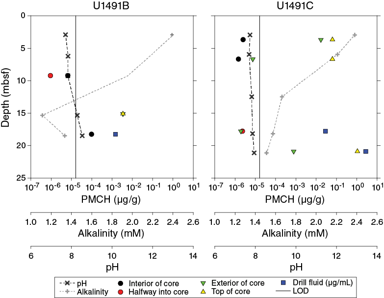
Figure F24. PMCH.
Physical properties
Physical property data were acquired on all Hole U1491B and U1491C cores with the exception of the core catchers, which are considered to be too disturbed for representative physical measurements. No measurements were made on Hole U1491A cores because the hole consists of only 1.32 m of sediments from an APC core barrel that remained in the BHA and was obtained as a “push core” while the drillers were finding the depth to seafloor (see Operations). Based on the analytical sequence presented in Physical properties in the Expedition 366 methods chapter (Fryer et al., 2018a), measurements were completed on whole rounds, section halves, and discrete samples. The Whole-Round Multisensor Logger (WRMSL) was used to measure wet bulk density using GRA, magnetic susceptibility, and P-wave velocity on the P-wave logger (PWL). Whole rounds were then logged for natural gamma radiation (NGR). Discrete thermal conductivity measurements were performed on two whole-round sections per core. Color reflectance and magnetic susceptibility were measured on archive section halves using the Section Half Multisensor Logger (SHMSL). In addition, shear strength (automated vane shear) was measured on the working section halves, and discrete samples were collected for moisture and density (MAD) measurements of wet and dry bulk densities. Physical property measurements were performed to help characterize the lithostratigraphic units and to describe the mechanical and thermal states of the serpentinite mud volcanoes. Raw data were uploaded to the Laboratory Information Management System (LIMS) database and subsequently filtered to remove spurious points that correspond to empty intervals in the liner or broken pieces. Onboard results and data interpretation are presented below.
Gamma ray attenuation bulk density
Hole U1491B
Bulk GRA density in Hole U1491B increases slightly but gradually from ~1.3 g/cm3 at the seafloor to ~1.75 g/cm3 at about 5 mbsf (Figure F25) and corresponds to lithostratigraphic Unit I, which is constituted of pelagic and volcanogenic muds with clasts (see Lithostratigraphy). These GRA bulk density values track the MAD measurements. At the transition from Unit I to Unit II (~4.6–5.4 mbsf), values become more scattered, but their average indicates an increase in GRA density. This increase corresponds to a layer with high contents of carbonate and lithic rock clasts within a fine clayey and water-saturated matrix with higher density and greater variability than the remainder of Unit I.
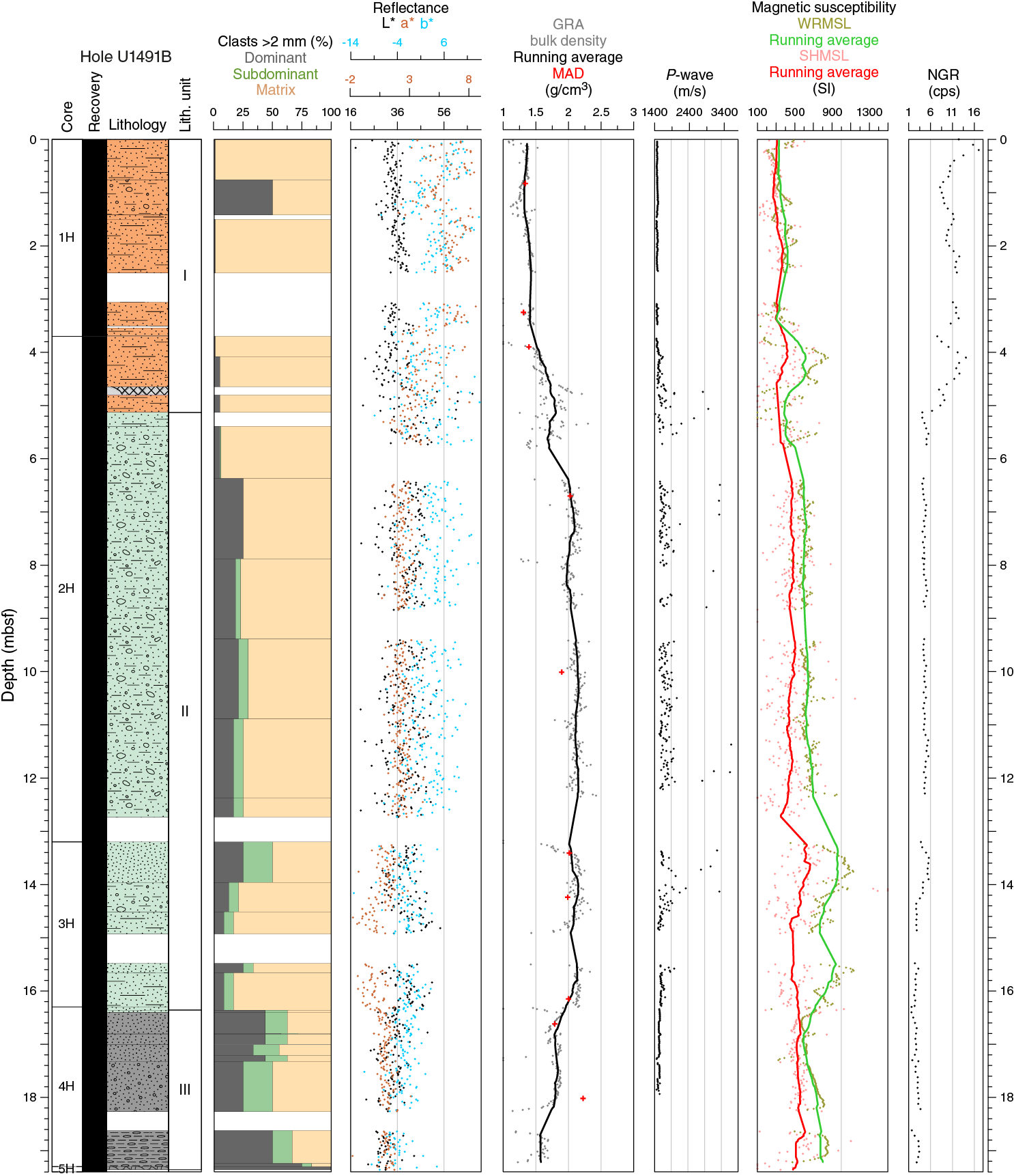
Figure F25. Physical properties, Hole U1491B.
From ~5.4 to ~16.4 mbsf, bulk GRA density is ~2.0 g/cm3 with little variability, and values are in good agreement with MAD values. This interval corresponds to Unit II, composed of serpentinite mud breccia with variable size lithic rock clasts that are most probably responsible for the observed variability in the GRA values.
From 16.4 mbsf to the base of the hole, a significant decrease in GRA to ~1.6–1.8 g/cm3 corresponds to the well-sorted pebbles of Unit III. This unit, as well as similar coarse, matrix-poor units in other holes from this expedition, probably represents fall-in of cuttings from farther uphole (see Lithostratigraphy). These values are lower than the MAD value of 2.2 g/cm3 obtained at 18 mbsf. This difference may be attributed to the loss of pore water that occurs during the subsampling for MAD in this type of pebbly recovery.
Hole U1491C
Bulk GRA density in Hole U1491C increases slightly and gradually from ~1.3 g/cm3 at the seafloor to ~1.5 g/cm3 at 7.51 mbsf (Figure F26), corresponding to Unit I, pelagic muds with clasts, and similar to the equivalent unit in Hole U1491B (Figure F25). These values are in agreement with the MAD measurements.
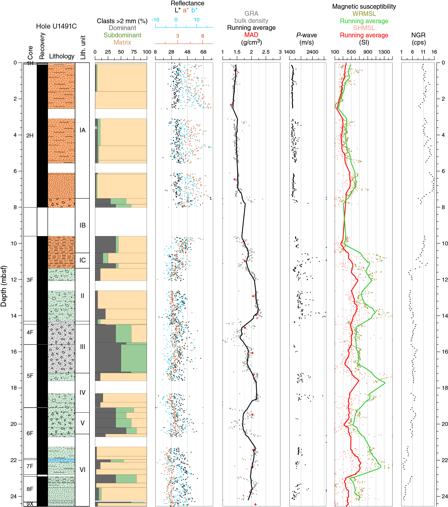
Figure F26. Physical properties, Hole U1491C.
Below this unit, GRA density shows higher variability with three distinct and similar trends starting from ~1.5 g/cm3 at the top of each interval (10.0, 14.5, and 19.4 mbsf) and increasing to 2.0 g/cm3 at the base (14.0 mbsf, 19.0 mbsf, and bottom of the core, respectively). All of these intervals correspond to serpentinite mud breccia with pebbly serpentinite mud breccia at their tops. These trends show good correspondence with MAD values (Figure F27).
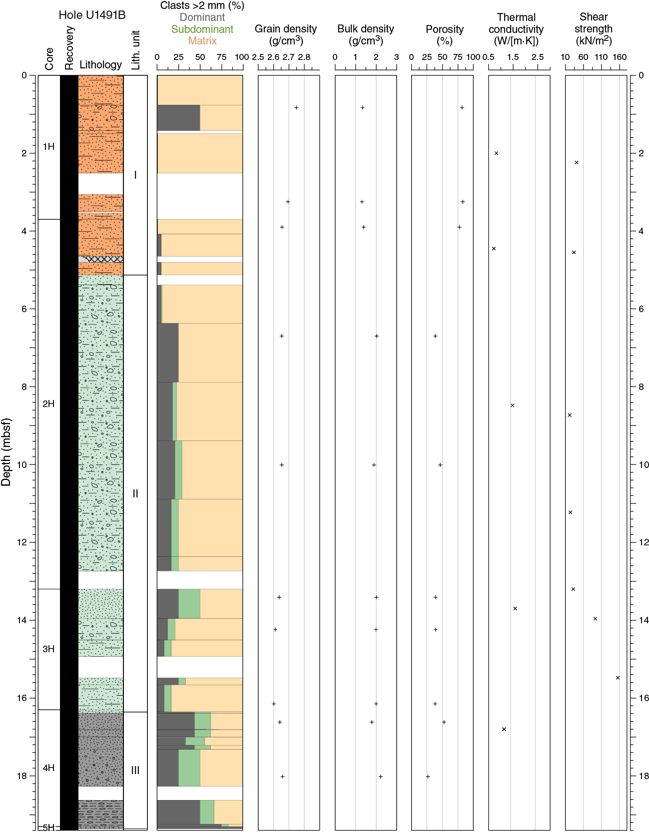
Figure F27. Index property data, thermal conductivity, and shear strength, Hole U1491B.
P-wave velocity
Whole-round and discrete P-wave measurements were performed using the WRMSL and the Section Half Measurement Gantry (SHMG). However, because of the high signal attenuation possibly related to high water content and the unconsolidated state of the mud material, the SHMG failed to acquire data. Therefore, only WRMSL data are used to describe Site U1491 P-wave velocity.
Hole U1491B
P-wave velocity in Hole U1491B shows near-constant values of ~1550 m/s over the upper 4.6 mbsf (Figure F25), corresponding to Unit I, which consists of pelagic muds with clasts. In Unit II, P-wave velocity becomes quite variable but increases to higher than 1700 m/s from 5.40 mbsf to the base of Unit II. This high variability reflects the significant clast size and density variability along the whole rounds of this lithostratigraphic unit. Unit III, consisting of well-sorted turbidite-like deposits composed of different sized and well-sorted ultramafic rock and carbonate pebbles (probably fall-in of cuttings; see Lithostratigraphy), is characterized by low P-wave velocity (~1600 m/s). Initially, mud material was presumed to have been elutriated away during the emplacement process of these deposits. Finally, these values are not representative of the P-wave velocity of the hard rock clasts and pebbles in Units II and III.
Hole U1491C
P-wave velocity variability in Hole U1491C (Figure F26) is very similar to that in Hole U1491B (Figure F25). The upper 7.5 m shows constant (~1550 m/s) and low variability in P-wave velocity that corresponds to Unit I, which consists of pelagic and volcanogenic mud with some clasts. Below this unit, from ~10 mbsf to the base of Hole U1491C, P-wave velocity is quite variable but increases to above 1700 m/s (with the exception of low velocity values associated with local intense disturbance and voids produced during the recovery of the cores).
Reflectance spectroscopy and colorimetry
Hole U1491B chromaticity variables a* and b* show high values, and L* is low in the uppermost 5.2 m, reflecting the brownish colors that correspond to Unit I, composed of pelagic sediments and oxidized serpentinite mud (Figure F25). Below this unit, b* is lower and relatively constant and L* is higher, indicative of greener and bluer material.
Hole U1491C reflectance parameters a* and b* show high values in the uppermost 11 m, reflecting the brownish colors that correspond to Subunits IA and 1B, composed of pelagic sediments and oxidized serpentinite mud (Figure F26). Below this unit, a* and b* have relatively constant and lower reflectance values indicative of greener and bluer material. L* data show no trend with lithology in this hole.
Magnetic susceptibility
Magnetic susceptibility is sensitive to the concentration and type of magnetic minerals, and data are extremely helpful in identifying sediment heterogeneities in terms of matrix and clast content of magnetite formed during serpentinization. In both holes, most of the magnetic susceptibility values recorded in the different lithostratigraphic units are more than 200 × 10−5 SI (Figures F25, F26). Significant changes in magnetic susceptibility are observed at the major lithologic boundary between the pelagic sediment of Unit I and the lower serpentinite mud of Units II and III and can be correlated with the other WRMSL measurements. Average magnetic susceptibility values in Unit I are 414 × 10−5 and 552 × 10−5 SI for Holes U1491B and U1491C, respectively. Units II and III in both holes have higher average values of 682 × 10−5 to 685 × 10−5 SI and 773 × 10−5 to 759 × 10−5 SI, respectively. Several prominent magnetic susceptibility variations with maximum peak values as high as 1200 × 10−5 SI were observed in the different serpentinite mud units. A magnetic susceptibility peak at ~13–14 mbsf in Hole U1491B coincides with an NGR peak. The other high magnetic susceptibility values (~15.5 mbsf in Hole U1491B and ~14, ~17–18, and ~22 mbsf in Hole U1491C) cannot be correlated to the other physical properties measured on whole rounds. Unit III in Hole U1491B, characterized by low mud content and high concentrations in ultramafic clasts, has magnetic susceptibility values similar to those measured in the upper part of the high-mud-content Unit II. Point magnetic susceptibility data are generally lower than those measured on whole rounds but have similar trends and local variations, with some exceptions corresponding to the biggest clasts, where point magnetic susceptibility assumes extremely high values.
Natural gamma radiation
NGR, recorded in counts per second, represents the concentrations of the elements potassium, uranium and thorium (see Physical properties in the Expedition 366 methods chapter [Fryer et al., 2018a]). In Holes U1491B and U1491C (Figures F25, F26), NGR varies from ~8 to ~16 counts/s between the seafloor and the bottom of the pelagic muddy sediments in Unit I. At the top of Unit II, distinct decreases in NGR were observed to relatively low values of less than 8 counts/s for the rest of Holes U1491B (Units II and III) and U1491C (Units II–VI) within the serpentinite muds. The relatively higher NGR in Unit I likely results from radiogenic elements commonly present in pelagic sediments, whereas the low NGR levels below this unit result from very low levels of K, U, and Th in ultramafic lithology–derived serpentinite material. In Hole U1491B, NGR values of ~4–6 counts/s were observed between the top of Unit II (5.13 mbsf) and about 14 mbsf. Below this depth, NGR values of ~2–4 counts/s were measured, and no significant changes were observed to the Unit II/III boundary (16.36 mbsf). In Hole U1491C, NGR values of ~4–6 counts/s were observed in Unit II. Values of ~5–8 counts/s occur between the top of Unit III and the bottom of Unit V, and values of ~1–5 counts/s occur in Unit VI.
Moisture and density
Dry density, bulk density, grain density, and porosity were calculated from cylindrical samples of approximately 7 cm3 taken from the working section halves with plastic syringes (see Physical properties in the Expedition 366 methods chapter [Fryer et al., 2018a]). Hole U1491B (Figure F27) appears more representative of the lithologies due to the high drilling disturbance in Hole U1491C (Figure F28); this discussion focuses on Hole U1491B.
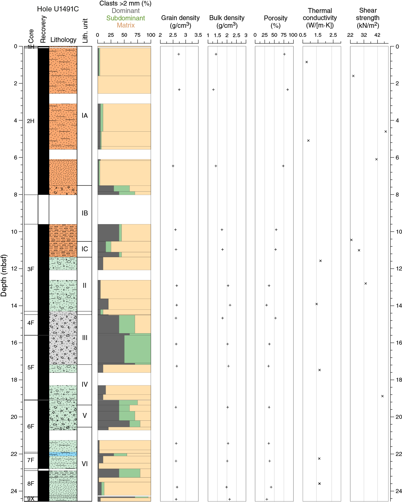
Figure F28. Index property data, thermal conductivity, and shear strength, Hole U1491C.
Bulk densities determined with MAD procedures in some cases have slightly lower average values than those measured with the WRMSL (Figures F25, F26). In Hole U1491B, average bulk densities are 1.4, 2.0, and 2.2 g/cm3 in Units I, II, and III, respectively. Bulk and dry densities have similar patterns with depth, with lower values in the pelagic sediment (Unit I), whereas grain density has the highest value in that interval. Calculated porosity is 80% in Unit I, as expected for marine pelagic sediment (Inderbitzen, 1974), whereas it is extremely low throughout Unit II (40%).
Throughout Unit II, grain density is almost constant around 2.64 g/cm3, reflecting the high degree of alteration of the ultramafic components and indicating that Unit II is mostly made of serpentinized material with little of the original ultramafic rock left.
Thermal conductivity
Thermal conductivity measurements were made in Holes U1491B and U1491C at a rate of two per core (usually in Sections 1 and 4 at the midpoint of the available length of the section). Values in both holes (Figures F27, F28) range between 0.74 and 1.80 W/(m·K) (average = 1.31 W/[m·K]). Values in the pelagic red clay from 0 to 8 mbsf average 0.77 W/(m·K), and deeper values average 1.48 W/(m·K) from 8.5 mbsf to the base of Hole U1491C.
Automated vane shear
Hole U1491B vane shear measurements (Figure F27) appear more representative of the lithologies due to the high drilling disturbance in Hole U1491C (Figure F28); this discussion focuses on Hole U1491B.
Shear strength measurements were made with the automated vane shear in cohesive sediments from Units I and II but not in the loose pebbles of Unit III because the vane shear is only effective in cohesive sediments. The upper meters recovered from Hole U1491B are normally consolidated muds with normal to little strength (20–40 kPa), possibly due to core disturbance. Shear strength increases from 32 to 155 kPa at ~14 mbsf (Figure F27) at the base of the serpentinite mud layer. Measurements were interrupted at about 16 mbsf because the lithology transitioned into pebbles.
Discussion
The physical property data collected at Site U1491 are in good agreement with the lithostratigraphic data (see Lithostratigraphy). The occurrence of pelagic deposits at the top of the section indicates that mudflows have not been active on the northeastern flank of Yinazao Seamount for some time; these conditions will be constrained by shore-based dating methods. The physical properties of the underlying serpentinite mud at Site U1491 are consistent with those measured on other seamounts of the Mariana forearc (Conical Seamount, ODP Leg 125 [Fryer, Pearce, Stokking, et al., 1992]; South Chamorro Seamount, ODP Leg 195 [Salisbury, Shinohara, Richter, et al., 2002]). The high peak values of magnetic susceptibility, about 10−2 SI, highlight the presence of magnetite in the serpentinite mud, classically associated with the process of serpentinization of ultramafic rocks (e.g., Bonnemains et al., 2016). The significant variations of this physical property may reflect heterogeneities in magnetite content associated with the ratio of muds to clasts. The effect of compaction is suggested by the overall increasing trend in GRA bulk density with depth in the upper 10 m, but the overall high bulk density values (>2.0 g/cm3) in the serpentinite mud (6–16 mbsf) suggest that additional porosity-reducing processes are also in play.
Downhole measurements
Measurements were attempted with the APCT-3 for Core 366-U1491B-2H at 9.5 mbsf and Core 5H at 19.4 mbsf. Temperature records in both deployments were of poor or questionable quality. The recorded decay curves were analyzed with the TP-Fit software (see Downhole measurements in the Expedition 366 methods chapter [Fryer et al., 2018a]), and temperatures were fit to the final one-third of the data window to estimate formation temperatures, which were combined to calculate the temperature gradient.
Temperature data from Core 2H exhibit small oscillations throughout the record and an abrupt steepening of the temperature decay ~60 s after insertion (Figure F29). In TP-Fit, the starting pick was set after this feature and the end was set as late as possible, providing a 10.7 min long record. The estimated temperature was 1.83°C, using the final third of the data window (Table T8).
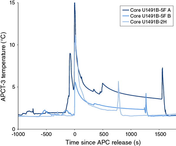
Figure F29. APCT-3 temperature measurements.
Table T8. APCT-3 temperature data. Download table in CSV format.
Core was not initially retrieved at 19.5 mbsf (Core 5H), requiring a second wireline trip. The temperature record therefore includes two penetrations (Figure F29), from which two formation temperature estimates were made from a single APCT-3 deployment. Data from the first penetration exhibits a sharp initial temperature increase of ~5°C, suggesting good penetration followed by a relatively smooth decay with a full 20 min record containing only a small 0.1°C increase at ~5 min. The start of the analysis was set after this feature, and the end was set as late as possible to include a full 12 min record. Data from the second penetration shows a higher temperature increase at the start of the deployment of over 15°C, suggesting better penetration than the first attempt, resulting in greater frictional heating. Part way through the record, there is an increase of ~1°C at ~500 s. The start of the analysis was set just after this thermal increase and ended as late as possible, resulting in a 17 min record of decay. On the basis of the final third of the data window, temperature estimates for the first and second penetrations are 1.72°C and 2.14°C, respectively (Table T8). The bottom seawater temperature is based on two stable sections that were selected for 5 min averages. These temperature records were recorded before the firing of Core 2H, which yielded a value of 1.52°C, and after the first penetration of Core 5H, which yielded a value of 1.57°C.
Calculated temperature data are plotted with depth in Figure F30. The higher temperature estimate of 2.14°C at 19.4 mbsf aligns better with the two shallower estimates, assuming a linear increase in temperature with depth. Using these three values yields a gradient of 30.2°C/km. Multiplying the gradient by the average measured thermal conductivity of 1.48 W/(m·K) results in a heat flow of 44.7 mW/m2. Including the lower temperature value of 1.72°C at 19.4 mbsf in the linear fit results in a gradient of 20.6°C/km and a heat flow of 30.5 mW/m2. This second estimate is considered better because extra frictional heating may have occurred because of the oscillations of the 9.5 m deployment and the second deployment at 19.4 m. Overall, the geothermal gradient and heat flow values at this site must be considered tentative due to the poor quality of the records and the shallow measurement depths.

Figure F30. APCT-3 formation and bottom seawater temperatures.
Heat flow values at Site U1491 and other sites located on the lower slopes of the seamounts are not expected to be perturbed by fluid discharge. Thus, they provide estimates of the background temperature gradient for comparison with the summit sites to quantify the heat transported by fluid discharge.
Paleomagnetism
The new 2G Enterprises liquid helium–free superconducting rock magnetometer (SRM) was installed at the start of Expedition 366 and was still being tested when the Site U1491 cores came aboard. The paleomagnetic analyses of archive section halves from Site U1491 started a few days later on 20 December 2016. Discrete samples were collected from three Hole U1491B cores and seven Hole U1491C cores. The remanent magnetization of the samples was measured after alternating field (AF) demagnetization to 0, 5, 15, 20, and 30 mT.
Three Hole U1491B and seven Hole U1491C archive section halves were measured. The remanent magnetization of almost all section halves was measured at 5 cm intervals after stepwise AF demagnetization to 0, 5, 10, 15, and 20 mT. A total of 20 representative discrete samples were collected. We analyzed NRM inclinations and declinations in Holes U1491B and U1491C from both discrete (Figure F31) and section-half measurements using PCA of the directions at each demagnetization step, using the PuffinPlot software. Cores where the unconsolidated material was sandy, watery, or heavily disturbed by the coring process were not measured.
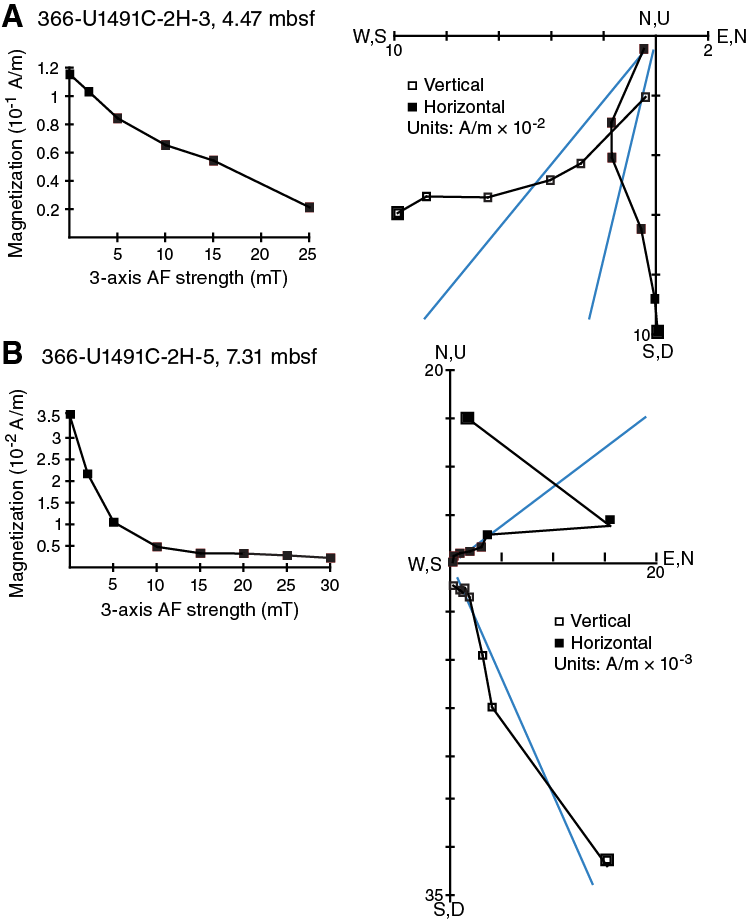
Figure F31. NRM decay and AF demagnetization vector.
Results
The paleomagnetic directions from discrete samples and section halves are generally consistent with one another. A vertical overprint, likely imparted by the drilling process, is in most cases largely demagnetized by AF demagnetization in peak fields of 5 mT. In some intervals, however, enough of the overprint remains after the 20 mT demagnetization step that the inclination remains anomalously high. At this site, latitude 13°N, the axial dipole inclination is expected to be 25°. NRM intensities vary with lithostratigraphic unit; for example, high intensities averaging 0.5 A/m were measured in the serpentinite mud from Hole U1491B, Unit II (Figure F32). The downhole pattern of NRM intensity generally covaries with the downhole pattern of magnetic susceptibility (see Physical properties).
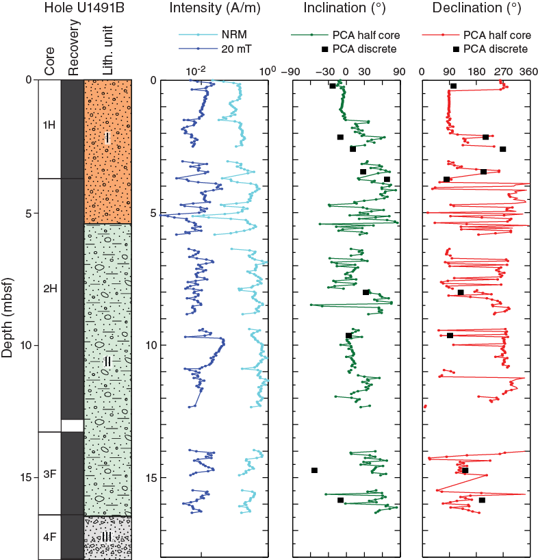
Figure F32. NRM intensity, inclination, and declination, Hole U1491B.
Initially, declination results at the 20 mT demagnetization step from Unit I in both holes suggested that one or more geomagnetic reversals may have been recorded (Figures F32, F33). Unit I corresponds to pelagic and volcanic brown silty sediments, so it was plausible that reversals could be present. However, PCA analysis of the demagnetization data did not show the same pattern of apparent ~180° swings in declination, and there was no clear correspondence of declination and inclination changes, as would be expected from reversals. Moreover, the sediment itself contains sandy silt beds, two or more dipping lithologic contacts, and some gravel- and pebble-sized clasts, meaning this heterogeneous sediment is not ideal for paleomagnetic recording of the field with sufficient fidelity.
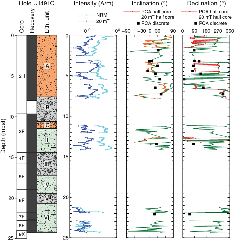
Figure F33. NRM intensity, inclination, and declination, Hole U1491C.
References
Andreani, M., Baronnet, A., Boullier, A.M., and Gratier, J.P., 2004. A microstructural study of a “crack-seal” type serpentine vein using SEM and TEM techniques. European Journal of Mineralogy, 16(4):585–595. https://doi.org/10.1127/0935-1221/2004/0016-0585
Bonnemains, D., Carlut, J., Escartín, J., Mével, C., Andreani, M., and Debret, B., 2016. Magnetic signatures of serpentinization at ophiolite complexes. Geochemistry, Geophysics, Geosystems, 17(8):2969–2986. https://doi.org/10.1002/2016GC006321
Eglinton, T.I., and Repeta, D.J., 2014. Organic matter in the contemporary ocean. In Mottl, M.J., and Elderfield, H. (Eds.), Treatise on Geochemistry (2nd Edition) (Volume 8): The Oceans and Marine Geochemistry. Holland, H.D., and Turekian, K.K. (Series Eds.): Oxford, United Kingdom (Elsevier), 151–189. https://doi.org/10.1016/B978-0-08-095975-7.00606-9
Engdahl, E.R., van der Hilst, R., and Buland, R., 1998. Global teleseismic earthquake relocation with improved travel times and procedures for depth determination. Bulletin of the Seismological Society of America, 88(3):722–743. http://www.bssaonline.org/content/88/3/722.abstract
Fryer, P., 2012. Serpentinite mud volcanism: observations, processes, and implications. Annual Review of Marine Science, 4(1):345–373. http://dx.doi.org/10.1146/annurev-marine-120710-100922
Fryer, P., Pearce, J.A., Stokking, L.B., et al., 1992. Proceedings of the Ocean Drilling Program, Scientific Results, 125: College Station, TX (Ocean Drilling Program). http://dx.doi.org/10.2973/odp.proc.sr.125.1992
Fryer, P., Wheat, C.G., Williams, T., Albers, E., Bekins, B., Debret, B.P.R., Deng, J., Dong, Y., Eickenbusch, P., Frery, E.A., Ichiyama, Y., Johnson, K., Johnston, R.M., Kevorkian, R.T., Kurz, W., Magalhaes, V., Mantovanelli, S.S., Menapace, W., Menzies, C.D., Michibayashi, K., Moyer, C.L., Mullane, K.K., Park, J.-W., Price, R.E., Ryan, J.G., Shervais, J.W., Sissmann, O.J., Suzuki, S., Takai, K., Walter, B., and Zhang, R., 2018a. Expedition 366 methods. In Fryer, P., Wheat, C.G., Williams, T., and the Expedition 366 Scientists, Mariana Convergent Margin and South Chamorro Seamount. Proceedings of the International Ocean Discovery Program, 366: College Station, TX (International Ocean Discovery Program). https://doi.org/10.14379/iodp.proc.366.102.2018
Fryer, P., Wheat, C.G., Williams, T., Albers, E., Bekins, B., Debret, B.P.R., Deng, J., Dong, Y., Eickenbusch, P., Frery, E.A., Ichiyama, Y., Johnson, K., Johnston, R.M., Kevorkian, R.T., Kurz, W., Magalhaes, V., Mantovanelli, S.S., Menapace, W., Menzies, C.D., Michibayashi, K., Moyer, C.L., Mullane, K.K., Park, J.-W., Price, R.E., Ryan, J.G., Shervais, J.W., Sissmann, O.J., Suzuki, S., Takai, K., Walter, B., and Zhang, R., 2018b. Expedition 366 summary. In Fryer, P., Wheat, C.G., Williams, T., and the Expedition 366 Scientists, Mariana Convergent Margin and South Chamorro Seamount. Proceedings of the International Ocean Discovery Program, 366: College Station, TX (International Ocean Discovery Program). https://doi.org/10.14379/iodp.proc.366.101.2018
Gratier, J.-P., and Gueydan, F., 2007. Effect of fracturing and fluid–rock interaction on seismic cycles. In Handy, M.R., Hirth, G., and Hovius, N. (Eds.), Tectonic Faults: Agents of Change on a Dynamic Earth: Chichester, United Kingdom (Wiley), 95:319–356.
Hulme, S.M., Wheat, C.G., Fryer, P., and Mottl, M.J., 2010. Pore water chemistry of the Mariana serpentinite mud volcanoes: a window to the seismogenic zone. Geochemistry, Geophysics, Geosystems, 11(1):Q01X09. http://dx.doi.org/10.1029/2009GC002674
Inderbitzen, A. (Ed.), 1974. Marine Science (Volume 2): Deep-Sea Sediments: Physical and Mechanical Properties: New York (Springer US). https:/doi.org/10.1007/978-1-4684-2754-7
Johnston, R.M., Ryan, J.G., and the Expedition 366 Scientists, 2018. pXRF and ICP-AES characterization of shipboard rocks and sediments: protocols and strategies. In Fryer, P., Wheat, C.G., Williams, T., and the Expedition 366 Scientists, Mariana Convergent Margin and South Chamorro Seamount. Proceedings of the International Ocean Discovery Program, 366: College Station, TX (International Ocean Discovery Program). https://doi.org/10.14379/iodp.proc.366.110.2018
Mottl, M.J., 1992. Pore waters from serpentinite seamounts in the Mariana and Izu-Bonin forearcs, Leg 125: evidence for volatiles from the subducting slab. In Fryer, P., Pearce, J.A., Stokking, L.B., et al., Proceedings of the Ocean Drilling Program, Scientific Results, 125: College Station, TX (Ocean Drilling Program), 373–385. https://doi.org/10.2973/odp.proc.sr.125.121.1992
Mottl, M.J., Komor, S.C., Fryer, P., and Moyer, C.L., 2003. Deep-slab fluids fuel extremophilic Archaea on a Mariana forearc serpentinite mud volcano: Ocean Drilling Program Leg 195. Geochemistry, Geophysics, Geosystems, 4:9009. http://dx.doi.org/10.1029/2003GC000588
Mottl, M.J., Wheat, C.G., Fryer, P., Gharib, J., and Martin, J.B., 2004. Chemistry of springs across the Mariana forearc shows progressive devolatilization of the subducting plate. Geochimica et Cosmochimica Acta, 68(23):4915–4933. http://dx.doi.org/10.1016/j.gca.2004.05.037
Oakley, A., 2008. A multi-channel seismic and bathymeric investigation of the central Mariana convergent margin [Ph.D. dissertation]. University of Hawaii. http://www.soest.hawaii.edu/GG/resources/theses/Oakley Dissertation 2008.pdf
Oakley, A.J., Taylor, B., Fryer, P., Moore, G.F., Goodliffe, A.M., and Morgan, J.K., 2007. Emplacement, growth, and gravitational deformation of serpentinite seamounts on the Mariana forearc. Geophysical Journal International, 170(2):615–634. http://dx.doi.org/10.1111/j.1365-246X.2007.03451.x
Oakley, A.J., Taylor, B., and Moore, G.F., 2008. Pacific plate subduction beneath the central Mariana and Izu-Bonin fore arcs: new insights from an old margin. Geochemistry, Geophysics, Geosystems, 9(6):Q06003. https://doi.org/10.1029/2007GC001820
Salisbury, M.H., Shinohara, M., Richter, C., et al., 2002. Proceedings of the Ocean Drilling Program, Initial Reports, 195: College Station, TX (Ocean Drilling Program). http://dx.doi.org/10.2973/odp.proc.ir.195.2002
1 Fryer, P., Wheat, C.G., Williams, T., Albers, E., Bekins, B., Debret, B.P.R., Deng, J., Dong, Y., Eickenbusch, P., Frery, E.A., Ichiyama, Y., Johnson, K., Johnston, R.M., Kevorkian, R.T., Kurz, W., Magalhaes, V., Mantovanelli, S.S., Menapace, W., Menzies, C.D., Michibayashi, K., Moyer, C.L., Mullane, K.K., Park, J.-W., Price, R.E., Ryan, J.G., Shervais, J.W., Sissmann, O.J., Suzuki, S., Takai, K., Walter, B., and Zhang, R., 2018. Site U1491. In Fryer, P., Wheat, C.G., Williams, T., and the Expedition 366 Scientists, Mariana Convergent Margin and South Chamorro Seamount. Proceedings of the International Ocean Discovery Program, 366: College Station, TX (International Ocean Discovery Program). https://doi.org/10.14379/iodp.proc.366.104.2018
2 Expedition 366 Scientists’ addresses.
This work is distributed under the Creative Commons Attribution 4.0 International (CC BY 4.0) license. 