| IODP Proceedings Volume contents Search | |||||||||||||||||||||||||||||||||||||||||||||
 | |||||||||||||||||||||||||||||||||||||||||||||
| Expedition reports Research results Supplementary material Drilling maps Expedition bibliography | |||||||||||||||||||||||||||||||||||||||||||||
|
doi:10.2204/iodp.proc.331.102.2011 Physical propertiesContinuous physical property measurements provide basic information through nondestructive means to assist characterization of lithological units and states of consolidation and deformation. For all core sections, X-ray CT images were captured first, followed by automated measurement of GRA density, P-wave velocity (PWV), and noncontact electrical resistivity using a MSCL-W. Cores were allowed to thermally equilibrate at room temperature, ~20°C (Expedition 315 Scientists, 2009; Expedition 316 Scientists, 2009), prior to these measurements. After MSCL-W measurements, thermal conductivity measurements were carried out on whole-round core sections for soft sediments and on the working half of split cores for hard sediments and rocks. Thermal conductivity was usually measured using a full-space needle probe method on soft sediments. In rare cases, we used a half-space line source probe method on split working halves because the sediments were lithified and could not be penetrated with the needle probe. Digital photo image scanning and color spectrophotometry were carried out on the split surfaces of archive halves using the MSCL-I and the MSCL color spectrophotometer (MSCL-C), respectively (Expedition 315 Scientists, 2009; Expedition 316 Scientists, 2009). MAD measurements were made on discrete samples collected from working halves; in general, discrete samples were taken once per section, and when possible, samples were taken from both above and below the whole rounds collected for microbiological and interstitial water sampling. Discrete measures of formation factor were determined from electrical resistivity (impedance) in working halves at two to three positions within each section. Discrete PWV measurements were conducted in three orthogonal directions in 20 mm cubic samples collected in lithified sediments. Details about each measurement are given in the following sections. Multisensor core logger for whole-round samplesGamma ray attenuation densityA thin gamma ray beam was produced by a 137Cs gamma ray source at a radiation level of 370 MBq within a lead shield with a 5 mm collimator. The gamma ray detector consisted of a scintillator and an integral photomultiplier tube. Calculation of bulk density from gamma ray attenuation utilized the following equation:
where
Because μ and Io are treated as constants, ρ can be calculated from I. We used a set of aligned aluminum cylinders of various thicknesses surrounded by distilled water in a sealed core liner for calibration. Gamma counts were taken through each cylinder (count time = 60 s), and ln(I) was plotted against (ρ × d). The density (ρ) of each aluminum cylinder was 2.7 g/cm3, and d was 1, 2, 3, 4, 5, or 6 cm. The relationship between I and (ρ × d) can be expressed as follows:
where A, B, and C are coefficients determined during calibration. The MSCL provided the values of I and d, and ρ was calculated with the equation above. This density measurement was conducted every 4 cm for a duration of 4 s. The spatial resolution of the measurement was 5 mm, so each data point reflects the properties of the closest 5 mm interval. Porosity (ϕ) is calculated from MSCL density assuming a solid grain density (ρs) of 2.7 g/cm3 and a pore fluid density (ρf) of 1.024 g/cm3:
P-wave velocityThe basic relationship for sonic velocity is
where
PWV transducers are mounted on the MSCL system and measure d and t horizontally throughout the entire core. Total traveltime measured between the transducers includes three types of correctable “delay”:
The effects of delays are calibrated using a core liner filled with pure water. For routine measurements on whole rounds in core liners,
where
Because of issues with reconfiguration of the MSCL-W for 4 inch diameter core sections, PWV measurements were not undertaken for cores taken with the BHI industry-standard coring system. This only applies to Core 331-C0013E-7L and all cores from Hole C0016B. Electrical resistivityThe bulk electrical resistivity (Re) of a core of length (L) and cross-sectional area (S) at constant temperature can be expressed as
where R is electrical resistance. The bulk resistivity of sediments and rocks is lower than that of the rock matrix because of the presence of relatively high conductivity fluids. The noncontact resistivity sensor on the MSCL system operates by inducing a high-frequency magnetic field in the core from a transmitter coil, which in turn induces electrical currents in the core that are inversely proportional to the resistivity. Very small magnetic fields generated by the electrical current are measured by a receiver coil. To measure these magnetic fields accurately, a different technique has been developed that compares readings generated from the measuring coils to readings from an identical set of coils operating in air. Electrical resistivity data were obtained at 4 cm intervals. Thermal conductivityThermal conductivity measurements were conducted on whole rounds using a needle probe method (VLQ probe) and/or on split cores using a half-space method (HLQ probe) and a TeKa TK04 thermal conductivity meter. The TK04 determines thermal conductivity based on a transient heat flow method. The heating wire and a temperature sensor are incorporated in a needle probe. When the wire is heated, the surface temperature of the probe is recorded simultaneously. The thermal conductivity of the surrounding material can be calculated from the temperature versus time measurement curve based on the simple calculation of the thermal conductivity coefficient:
where
Because ka(t) is not constant but depends on the time interval used for calculation of thermal conductivity, the real thermal conductivity is approached only for sufficiently large heating times. A special approximation method in the TK04 software automatically detects disturbances and determines the optimal time interval of the heating curve for evaluation. Heating power and evaluation parameters are changed depending on the specific sample. In general, thermal conductivity measurements are made twice in each core section. For whole-round cores, a small hole was drilled in the core liner, usually ~26 and ~100 cm from the top of each section. A 2 mm diameter temperature probe (VLQ) was inserted into the working half of the core section. At the beginning of each measurement, temperature in the samples was monitored automatically without applying a heater current until the background thermal drift was determined to be <0.2 mK/h. The heater circuit closed automatically, and the temperature increase in the probe was recorded. For cores that were too consolidated to permit use of the needle probe, we used a half-space method measurement. Briefly, an ~10 cm long split-core piece was taken from the working half of the core and placed in seawater at ambient temperature (20°C) for 15 min. The HLQ probe was placed on a flat surface of the sample with the line probe oriented parallel to the core axis, and heating and measurements were conducted automatically. The core and the probe were placed in an insulating cooler, wrapped in a soft cloth, and covered with a piece of bubble-wrap to maintain the ambient temperature. The measurement of temperature drift and conductivity was conducted in the same way as with the VLQ probe. During each 24 h period, the TK04 was calibrated using standard blocks that have nominal conductivities of 1.623 W/(m·K) ± 2% for the VLQ probe and 1.652 W/(m·K) ± 2% for the HLQ probe, respectively. Measurements for the standard blocks were then plotted against the true values, and the slope of the linear regression obtained was used to calibrate core sample measurements. Moisture and densityMAD measurements on rocks and sediments were calculated by measuring wet mass, dry mass, and dry volume. Core samplesDiscrete samples of ~5–7 cm3 were taken for each measurement at a spacing of approximately one sample per each working-half section. In addition, for those sections where whole rounds were removed for microbiological and interstitial water sampling, MAD samples were routinely taken both above and below (i.e., “bracketing”) the whole-round sample. In general, care was taken to sample undisturbed parts of the core and to avoid drilling mud. In soft sediments, samples were collected using a cut-off 10 cm3 syringe as a small piston core. When present, hard sediments and rock samples were cut into 2 cm × 2 cm × 2 cm cubes with a parallel-blade rock saw and then soaked for 6 h in a 35 ppt NaCl solution prior to MAD measurements. Immediately after the samples were collected, wet sediment mass (Mw) was measured. Dry sediment mass (Md) and dry volume (Vd) were measured at room temperature after drying the sample in a convection oven for 24 h at 105° ± 5°C and cooling the sample for 1 h in a room-temperature desiccator. Wet and dry masses were determined by weighing using a custom-built BAL-2 motion-compensated shipboard system of paired electronic balances that compensate for the ship’s heave. The sample mass was counterbalanced with a precisely known mass (usually 10 g) that was within 5 g of the sample mass. The sample mass was determined to a precision of at least ±0.01 g (generally better). The balance system was calibrated once each day. Dry volume was measured using a helium-displacement pycnometer (Quantachrome pentapycnometer) with a nominal precision of ±0.04 cm3. Volume measurements were repeated a minimum of three and up to five times until the standard deviation of the average volume was within ±0.2%. A reference volume (calibrated sphere) was run with each group of four samples, and the sphere was rotated between cells to check for systematic error. Bulk density, dry density, and density of the solids, as well as porosity and moisture content (void ratio), were computed, taking into account the precipitation of dissolved salts during drying using traditional IODP methods (Method C; Blum, 1997). Water content, porosity, and void ratio are defined by the mass (or volume) of extracted water before and after removal of all water present in the sample through the drying process. This includes interstitial water (inside the pores) as well as water sorbed to hydrous minerals. Standard seawater density (ρw = 1.025 g/cm3) is assumed for pore fluid density. Mass of water, mass of salt, volume of water, and water contentPore water mass (Mw), mass of salt (Ms), pore water volume (Vpw), and salt volume (Vs) can be calculated by
and
where
Bulk densityBulk density (ρ) is the density of the saturated samples defined as
Bulk mass (Mt) is measured with the balance, and bulk volume (Vt) is determined from the pycnometer measurement of dry volume (Vd) and the calculated volumes of pore fluid and salt (Vt = Vpw + Vd). PorosityPorosity (ϕ) was calculated using
where
Grain densityGrain density (ρgrain) was determined from measurements of dry mass and dry volume made in the balance and in the pycnometer, respectively. Mass and volume were corrected for salt using
where
Water contentWater content (Wc) was determined following the methods of the American Society for Testing and Materials (ASTM) designation D2216 (ASTM International, 1990). Corrections are required for salt when measuring the water content of marine samples. In addition to the recommended water content calculation in ASTM D2216 (i.e., the ratio of pore fluid mass to dry sediment mass, percent dry weight [% dry wt]), we also calculated the ratio of pore fluid mass to total sample mass (percent wet weight [% wet wt]). The equations for water content are
and
where
Discrete measurement of formation factor (electrical resistivity)In addition to bulk resistivity measurements from the MSCL-W, discrete measurements of electrical resistivity were made in order to calculate formation factor. The effect of pore fluid on bulk resistivity depends on whether the fluid-filled pores are connected. The bulk electrical resistivity of a fluid-filled sediment (Re) relative to that of the pore fluid (Rf) alone is described by an apparent formation factor Fa (Archie, 1947):
The formation factor is correlated with pore structure within the core (porosity, permeability, tortuosity, and so on). Values of Fa include the effect of grain-surface conductivity and thus do not represent the true formation factor,
where
Resistivity of pore water and sediment (Rf and Re, respectively) is calculated from the measured absolute impedance (|Z|) and phase angle (Θ):
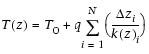
In practice, we assume that pore water has the same resistivity as seawater and record the resistivity of a 35‰ NaCl solution rather than the resistivity of the pore water. EquipmentElectrical resistivity was measured in working-half cores using a home-built electrode and an Agilent 4294 impedance analyzer. This system was developed onboard the Chikyu. The two terminal electrodes comprise two aluminum plates separated by an acrylic block (plates are 1 cm × 2 cm in area, with 2 cm clearance between the electrodes; this yields an electrode constant of 0.02 Ωm). Calibration of the system was performed once each day and consists of measuring the upper and lower resistivity ranges. The upper range (i.e., infinite resistivity) is measured with the two electrodes spaced 2 cm apart in air; the lower range (i.e., the short-circuit condition) is measured with the electrodes touching each other (pinched together by hand). This is followed by measurement of a 35‰ NaCl solution as a quality control check. The NaCl solution measurement should be done once per day or more frequently if the measurement is drifting unacceptably. The voltage and current signal levels for the impedance analyzer are 500 mV and 20 mA, respectively. The alternating-current frequency is swept from 40 to 110 MHz. The measurement of impedance is frequency dependent because there are polarization effects. Phase angles for both the NaCl solution and sediments have been empirically determined to be nearly zero between 10 and 1000 kHz; we record impedance data at a frequency of 100 kHz. Measurements in sediments and seawaterFor split cores, electrodes are placed into the sediment with the 2 cm opening aligned to the long axis of the core in order to minimize edge effects. Impedance and phase angle are recorded after approximately three scans to ensure signal stability. These planar electrodes are only suitable for relatively soft sediments. If the sediments crack upon insertion of the electrodes, the measured impedance will reflect an artificially high resistivity due to air-filled void spaces introduced upon cracking. Measurements were not made when sediments cracked upon electrode insertion. The Chikyu does not yet have a needle-type electrode system that will work in more consolidated sediments. Impedance measurements were made at least once per section (minimally at the depths corresponding to the thermal conductivity and MAD measurements) and generally, assuming good recovery, at two to three positions in each section. Care was taken not to disturb a significant portion of the sediment during the measurement. For NaCl reference solution measurements, the same electrode was used. The electrode was cleaned with distilled water and placed in a beaker of 35‰ NaCl. The electrode was lowered into the solution just to the depth of the acrylic spacer to ensure the water was measured in the same geometric configuration as in the cores. Discrete measurements of P-wave velocity and anisotropyPWV was measured on discrete samples taken from cores at a sampling frequency of roughly one per section. Core pieces were cut with a rock saw equipped with two parallel blades spaced 20 mm apart. This sample preparation enables measurement of P-wave anisotropies in three orthogonal directions. All cubes were cut with faces orthogonal to the x-, y-, and z-axes of the core reference and were soaked in a 35‰ NaCl solution for 6 h prior to analysis. Orientation of the axes is defined as the z-axis pointing down the core axis, the x-axis pointing into the working half, and the y-axis pointing along the core face. A newly installed P-wave logger for discrete samples (PWL-D) was used (Geotek LTD, London, UK). Its basic measurement principle is to measure P-wave traveltime and sample length and then calculate PWV. To measure PWV along a given direction, the sample is held by two 1.5 kg weights with a force of ~30 N (corresponding to a pressure of 75 kPa) between two transducers covered with rubber spacers to ensure good contact between the sample and the transducers. Both the transmitter and receiver are a type of Piezo-composite transducer, and the frequency of the compressible wave (P-wave) generated by the transmitter is 230 kHz. The transmitter is connected to a pulse generator; the receiver is connected to an amplifier, and the received signal is processed through an analog-to-digital converter (and then displayed on a PC). The traveltime is picked and logged automatically based on a threshold set by the operator. The sample dimension in the P-wave path is automatically measured at the same time as the traveltime measurement by a distance laser sensor mounted in the apparatus. Quality control checks are conducted daily using a glass sample and an acrylic sample. Calibrations of traveltime and laser distance sensor corrections were conducted only when quality control checks failed to meet designated specifications. The traveltime offset was determined by placing the transmitter and the receiver in direct contact and measuring traveltime. This setup has a time offset of ~9.8 ms. The offset is subtracted from the total traveltime to obtain the true traveltime through the sample. The velocity along a given direction is given by the sample dimension divided by the traveltime. Laser distance calibration was made by placing the transmitter and the receiver in direct contact (zero distance) and then spacing the transducers with a brass reference piece of 2.5 cm height. P-wave velocity anisotropyThree directional measurements on discrete samples for PWV were performed on hard sediment and rock samples. Core pieces were cut with a saw equipped with two parallel disks spaced 20 mm apart. If the core has no (or subhorizontal) apparent stratification or foliation, cubes are cut with faces 1, 2, and 3 orthogonal to the x-, y- and z-axes of the core reference, respectively. Orientation of the axes is the same as for paleomagnetism, with the z-axis pointing down along the core axis, the x-axis pointing into the working half, and the y-axis pointing along the core face. In situ temperature measurementsIn situ temperature measurements were made using the APCT3 tool in conjunction with the HPCS. The APCT3 consists of three components: electronics, coring hardware, and computer software. During Expedition 331, in situ temperature measurements were attempted at Sites C0013, C0014, and C0017 during HPCS coring. Temperature sensors were calibrated for a working range of 0° to 50°C, and the instrument can measure a maximum temperature of 55°C. Prior to entering the hole, the instrument was held at the approximate mudline for ~5 min to thermally equilibrate with the bottom water. This step provides both a clear time-series initiation point and a more accurate bottom water temperature from which to determine relative downhole temperature changes. Because the core winch depth meter was not calibrated, site-to-site variability in the measured bottom water temperature is likely due to uncertainties in depth. After equilibration, the tool was lowered down the hole and penetrated the formation, causing a rise in temperature due to frictional heating. Following the initial rise in temperature, measured temperatures decreased along a decay curve to near equilibrium. During this decay phase, it is important that the temperature tool is not disturbed; thus, drilling was halted for ~5 min to record temperatures. A second rise in temperature is due to frictional heating as the tool is pulled out of the formation. Temperature was measured as a time series sampled once per second and logged to a microprocessor within the downhole tool; when the tool was retrieved, data were downloaded to a computer. The formation equilibrium temperature is determined based on fitting the temperature decay curve using the program TP-Fit, which runs on Matlab (M. Heeseman, pers. comm., 2007). Determination of heat flowIf heat transfer is by conduction and heat flow is constant, the thermal gradient will be inversely proportional to thermal conductivity, according to Fourier’s law. This relationship can be linearized by plotting temperature as a function of summed thermal resistance (Bullard, 1939). If summed thermal resistance is
where
then
where
In practice, q and T0 are estimated by plotting T(z) against summed thermal resistance. Multisensor core logger imaging systemThe MSCL-I scans the surface of archive-half cores and creates a digital image. The line-scan camera is equipped with three charge-coupled devices (CCDs), each with 1024 arrays. Light reflection from the sample surface passes through the lens and is split into three paths (red, green, and blue) by a beam splitter inside the line-scan camera. Each reflection is then detected by the corresponding CCD. Finally, the signals are recombined to produce a digital image. Optical distortion downcore is prevented by precise movement of the camera. Spatial resolution is 100 pixels/cm. Multisensor core logger color spectroscopy loggerA color spectrophotometer (Konica-Minolta, CM- 2600d) is included on the MSCL-C system. The x-y-z type aluminum frame allows operators to set a maximum of seven core sections on the tray, and the sensor unit (including the spectrophotometer and small distance measuring system using a laser sensor) moves across each section and is lowered at each measurement point to measure the split archive core surface. Light reflected from the sample surface is collected in the color spectrophotometer’s integration sphere. The instrument’s structure allows for the specular component to be included (SCI setting) or excluded (SCE setting). The SCE setting is the recommended mode of operation, especially for sediments, in order to exclude glare. The light is then divided into wavelengths at a 10 nm pitch (400–700 nm), and the spectral sensors in the sphere convert the light to an electrical current proportional to the intensity of the light. Next, the color spectrum from the sample is normalized by the source light of the reflectance. The spectrum obtained is calibrated based on the measurement of a pure white (high) standard and a black box (zero) standard. The pure white standard has a high reflectance true value at visible wavelengths and is measured by the vendor. Measurements can be calculated based on the 2° or 10° standard observer and any of 11 illuminants. Color reflectance is categorized as an IODP standard measurement, and the measured color spectrum is normally converted to L*, a*, and b* parameters. L*, a*, and b* provide relative changes in the composition of the bulk material and are widely used to correlate sections from core-to-core or hole-to-hole and to analyze the characteristics and cyclicity of lithological changes. |
|||||||||||||||||||||||||||||||||||||||||||||

 ,
,