Betzler, C., Eberli, G.P., Alvarez Zarikian, C.A., and the Expedition 359 Scientists
Proceedings of the International Ocean Discovery Program Volume 359
publications.iodp.org
doi:10.14379/iodp.proc.359.105.2017
Site U14671
C. Betzler, G.P. Eberli, C.A. Alvarez Zarikian, M. Alonso-García, O.M. Bialik, C.L. Blättler, J.A. Guo, S. Haffen, S. Horozal, M. Inoue, L. Jovane, D. Kroon, L. Lanci, J.C. Laya, A. Ling Hui Mee, T. Lüdmann, M. Nakakuni, B.N. Nath, K. Niino, L.M. Petruny, S.D. Pratiwi, J.J.G. Reijmer, J. Reolid, A.L. Slagle, C.R. Sloss, X. Su, P.K. Swart, J.D. Wright, Z. Yao, and J.R. Young2
Keywords: International Ocean Discovery Program, IODP, JOIDES Resolution, Expedition 359, Site U1467, Maldives, Kardiva Channel, Goidhoo atoll, Indian Ocean paleoceanography, Oligocene, Miocene, Pliocene, Pleistocene, carbonate platform, carbonate platform drowning, celestine, dolomite, drift deposits, large benthic foraminifers, monsoon, sea level, sequence stratigraphy
MS 359-105: Published 4 May 2017
Background and objectives
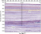
Site U1467 (proposed Site MAL-9A) is the easternmost site drilled in the Inner Sea of the Maldives during International Ocean Discovery Program (IODP) Expedition 359. It is located at 4°51.0274′N, 73°17.0223′E, at a water depth of 487 m; it lies 24.8 km east of the eastern end of the northern transect and 29.4 km east of the eastern end of the southern transect (Figure F1). Cores from this site record a 630 m thick succession of drift deposits (Figure F2) lining the southern flank of the Kardiva Channel. The main objectives at this site were (1) to constrain the timing of sequence boundaries in the drift succession, (2) to precisely date the onset of drift deposition so that we could analyze the cyclostratigraphy of carbonate drift deposits and reconstruct changes in the current regime and monsoon cyclicity, and (3) to recover an undisturbed sedimentary sequence for further paleoceanographic studies.
The mid-Miocene to recent drift succession contains several sequences that are likely caused by fluctuations in the current system flowing through the Kardiva Channel. Dating these sequence boundaries will provide the ages of changes in current strength and direction. Linking these physical stratigraphic data with postexpedition sedimentological and geochemical data will address the question of changes in monsoon intensity. Moreover, the periplatform sediments deposited at this site offer the opportunity to retrieve a complete δ13C record through the middle Miocene that together with the other Expedition 359 sites will provide another data set of the carbon isotopic record needed to calibrate the periplatform record against the pelagic record.
Operations
Transit to Site U1467
The short transit from Site U1465 to Site U1467 was completed in 2 h at 8.5 kt. At 2045 h on 28 October 2015, the ship was under dynamic positioning (DP) control over the site coordinates. We prepared an advanced piston corer (APC)/extended core barrel (XCB) bottom-hole assembly (BHA) including a nonmagnetic drill collar for oriented piston coring and a mechanical bit release (MBR) for eventual wireline logging and as insurance for freeing a stuck BHA.
Hole U1467A
Hole U1467A was spudded at 0055 h on 29 October 2015 with the bit positioned at 481 meters below sea level (mbsl). Core 1H recovered 3.5 m and established a seafloor depth of 487 m. Oriented piston coring continued through Core 4H to 32.0 meters below seafloor (mbsf); a single formation temperature measurement (with the advanced piston corer temperature tool [APCT-3]) was made while recovering Core 3H at 22.5 mbsf. Right from the start, the coring system was not behaving normally. Barrels were seating high and then dropping down while under 300–400 psi pressure; the resultant jarring impact caused the shear pins to shear and the barrels to fully stroke. To free the core barrels, 5000 lb of overpull was necessary. In an attempt to determine whether there was some sort of blockage or a broken flapper valve, an XCB core barrel was deployed. This barrel also landed high and also experienced an initial 5000 lb overpull. Convinced that something was wrong in the BHA, we decided to abandon the hole, recover the drill string, and inspect the coring assembly. The bit arrived back on the rig floor at 0900 h on 29 October. Upon inspection of the coring tools, the MBR, float valve, and landing shoulders were all determined to be in good shape, but further inspection determined that the XCB latch sleeve was damaged, which was why the wireline barrels were jamming upon deployment and recovery. The latch sub and sleeve were replaced. The drill string was deployed back to the seafloor, and Hole U1467B was spudded at 1430 h.
Hole U1467B
In Hole U1467B, Core 1H recovered 3.46 m and established a water depth of 487 m. Oriented APC coring continued through Core 37H to 338 mbsf. Formation temperature measurements (APCT-3) were made while taking Cores 3H, 5H, 7H, and 9H (22.5, 41.5, 60.5, and 79.5 mbsf, respectively); however, all the temperature measurements appear to be erroneous. At 2100 h on 29 October 2015, after reaching refusal with the half-length APC (HLAPC) (Core 42F at 361.4 mbsf), coring was suspended in order to test the Motion Decoupled Hydraulic Delivery System (MDHDS) and Electronic RS (ERS) overshot system.
The MDHDS is being developed for use when deploying the temperature dual-pressure tool (T2P); however, it can also be used to deploy the Sediment Temperature Tool (SET), SET2, and sediment temperature/pressure tool (SETP). The ERS will also be useful for deploying future CORK thermistor strings. Both systems are deployed with the conductor cable or “wireline” that is used primarily for downhole logging. The MDHDS system was assembled and hung off at the rig floor, and the ERS was attached to the top of the MDHDS. The system was deployed into the hole using the wireline, but all communication with the ERS was lost and the tool had to be recovered back to the rig floor. Subsequent testing indicated that a component had failed in the ERS electronic module. This was repaired, and the tool was deployed back into the hole. During the descent, however, a concern was raised about the compatibility of the MDHDS/SET system with the standard MBR and float valve assembly in the deployed BHA. The MDHDS is designed to be deployed through a lockable float valve (LFV) and was deployed in this manner on a previous expedition. In this case, a MBR was being run in lieu of a LFV because it provided another way to free up the drill string should it become stuck in the hole. The test was suspended, and after an assessment, it appeared the MDHDS system was compatible. The SET tool being deployed was also compatible as long as the shear pins were not sheared in the SET tool, as would be the case when taking a normal temperature measurement. There was no plan to do this during the MDHDS test; however, there was some concern that if the shear pins accidentally sheared and the SET tool scoped out, it would be impossible to recover it inside the BHA because the float valve flapper engages a square shoulder. Because of this potential risk to a high-value hole, the test was suspended and the tools were pulled out of the hole. The system was back at the rig floor just before 0300 h on 31 October.
Continuous oriented APC coring resumed and continued until 0615 h on 31 October, when Core 45H reached 389.9 mbsf. Core 45H achieved a full stroke, but at 100,000 lb overpull the barrel required drillover with the XCB core bit. Coring then continued using the HLAPC through Core 61F to 465.1 mbsf. Coring with the HLAPC was suspended when the last two cores each had 100,000 lb overpull and required drillover. At 1530 h, we switched to the XCB coring system. Coring continued through Core 77X to 617.2 mbsf (see Figure F1 in the Expedition 359 summary chapter [Betzler et al., 2017b]). At that time, the assistant driller noted that he was getting high (10,000 lb) overpull when recovering XCB core barrels. The HLAPC was deployed, and this barrel landed high. After pressuring up the drill string, the shear pins prematurely sheared at 400 psi (upon impact) after being pushed through the XCB double window latch sleeve. These were the same symptoms experienced earlier in Hole U1467A with the XCB latch sleeve. With the hole only 97 m from the desired total depth, a meeting was called with the Co-Chief Scientists and technical personnel to discuss options. We decided to stop coring Hole U1467B, recover/repair the BHA, and modify the plan for Hole U1467C. APC coring to 200 m was already planned for Hole U1467C, so we planned to add drilling to ~610 m, XCB coring to the target depth, and wireline logging.
Hole U1467C
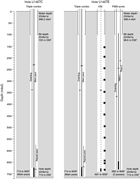
The drill string was recovered, the XCB latch sleeve was replaced, the ship was offset 20 m north of Hole U1467B, and Hole U1467C was started at 1620 h on 1 November 2015. Core 1H established a seafloor depth of 487 m. By 0000 h on 1 November, we extended coring to 111.2 mbsf (Cores 2H–12H). Coring continued the next day using the APC coring system through Core 22H to 198.7 mbsf. The XCB was then used to drill ahead to 325.8 mbsf before a center bit had to be deployed. The XCB with center bit advanced to 578.6 mbsf, and the center bit was recovered via wireline. At 2030 h on 2 November, XCB coring was initiated, and it continued through Core 37X to 714.0 mbsf, the Environmental Protection and Safety Panel–approved depth for the site (see Figure F1 in the Expedition 359 summary chapter [Betzler et al., 2017b]). A mud sweep was circulated to clean the hole one final time, and the drill string was recovered and spaced out for wireline logging with the bit placed at 101.8 mbsf.
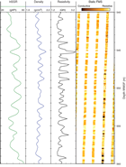
At 1400 h on 3 November, wireline logging began. As the triple combo tool string was being made up, the rig crew noted backflow of water coming from the tool joint at the rig floor. The triple combo tool string was removed so we could add heavy mud in the drill pipe to prevent further backflow. While attempting to reinsert the tool string, a fiberglass connection on the bottom of the magnetic susceptibility tool broke off and the connected LFV go-devil fell through the drill string. This was not a significant concern because these go-devils were free-fall deployed in the past. After manufacturing a new fiberglass connector sleeve and changing out the magnetic susceptibility sonde with the onboard spare, the triple combo tool string was redeployed. The tool string was run to the total depth of the hole (714 mbsf) without any problems. After completing the first logging run, it was determined that the borehole diameter was too large (>17 inches) for collecting useful data with the Formation MicroScanner (FMS)-sonic and Versatile Seismic Imager (VSI) tool strings. Therefore, the triple combo tool string was recovered and the tools were rigged down. We then decided to drill a dedicated logging hole utilizing a 9⅞ inch tricone drill bit after completing one additional APC hole to ~200 mbsf. The drill string was pulled clear of the seafloor at 0010 h on 4 November.
Hole U1467D
The top drive was picked up, the drill string was spaced out to 1.5 mbsf, and coring in Hole U1467D started at 0130 h on 4 November 2015. This space-out was used to spread out the breaks between cores in adjacent holes to enable the recovery of a complete section for paleoceanographic studies. APC coring (not oriented) continued through Core 22H to 201.0 mbsf. The drill string was then recovered on ship, with the bit arriving on the rig floor at 1325 h on 4 November.
Hole U1467E
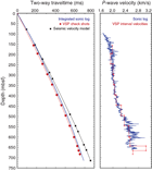
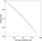
Our final operation at Site U1467 was to drill a dedicated logging hole. The ship was offset 20 m east of Hole U1467A. The BHA was changed to a noncoring drill bit, and the drill string was lowered back to the seafloor. The top drive was picked up, and the drill string was spaced out using an offset seafloor depth of 498.4 mbsf taken from Hole U1467A. Drilling in Hole U1467E started at 1710 h on 4 November 2015. This dedicated logging hole was drilled without coring to 714.0 mbsf in 25 h. A mud sweep was circulated to clear cuttings out of the hole, and two wireline runs were made to release the bit at the bottom of the hole and reverse shift the MBR sleeve. Because of the stability seen in the previous holes at this site and while drilling the hole, we decided that a wiper trip was not necessary, and there was no need to displace the hole with heavy mud. The drill string was raised up the hole, and the end of the pipe was placed at 98.6 mbsf. We started rigging up for wireline logging at 2230 h on 5 November. The triple combo was run into the hole and reached the total depth at 714.0 mbsf. Caliper logs from this deployment indicated a hole diameter of 11–17 inches. The triple combo tool string was recovered and rigged down by 0600 h on 6 November. Taking advantage of daylight and following the marine mammal protection protocol, the vertical seismic profile (VSP) experiment was conducted next. The VSI tool was able to reach ~684 mbsf or ~30 m off bottom, apparently because of fill in the borehole, and data were collected uphole from there. A very good signal was received at each VSP station, thus providing the necessary information for an accurate time-depth conversion for comparison of seismic and downhole (core and logging) data. The FMS-sonic tool string was deployed at 1200 h on 6 November and reached 664 mbsf, where it stopped because of further fill at the bottom of the borehole. One of the four FMS pads was not recording accurate data because it was covered with grease, which prevented good contact between the pad and the borehole wall. After the FMS-sonic data were obtained, the tool string was recovered and rigged down by 1900 h on 6 November.
The rig floor was secured from logging operations by 2000 h, and by 2015 h the upper guide horn was raised in preparation for pressure testing the new fiber optics–based subsea camera system. The camera was deployed down the drill string to the seafloor. This system was installed prior to the last expedition (356); however, because of the shallow-water operating depths, the system has only been tested to ~90 meters below rig floor (mbrf). We needed to test this system prior to the next expedition (360), which will require multiple deployments of the system for making bit changes in the course of drilling a single 1500 m rotary core barrel (RCB) hole into gabbro in ~700 m of water. Testing the camera system at Site U1467 (473 m) indicated that the system is 100% operational. The camera was back on board and secured within 1 h, and the drill string was pulled clear of the seafloor and recovered to the ship. After the seafloor positioning beacon was recovered and the ship was secured for transit, we began the ~13.6 nmi transit to Site U1468 at 0024 h on 7 November.
Total recovery for Site U1467 was 31.49 m (98%) in Hole U1467A, 560.4 m (91%) in Hole U1466B, 266.15 m (80%) in Hole U1467C, and 203.7 (102%) in Hole U1467D (Table T1). Of the 137 cores recovered, 86 were full APC cores, 21 were HLAPC cores, and 30 were XCB cores (see Figure F1 in the Expedition 359 summary chapter [Betzler et al., 2017b]).
Table T1. Site U1467 core summary. Download table in .csv format. View PDF table.
Lithostratigraphy
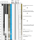
Site U1467 was drilled through a sequence of drift deposits in the Kardiva Channel and into the underlying basinal deposits of the carbonate platform as indicated on seismic profiles (see Seismic stratigraphy). Lithostratigraphic units were defined by combining data from the four holes cored at this site (Holes U1467A–U1467D) (Figure F3). The 708 m thick sequence was texturally constant with only minor variations in composition and degree of lithification. Color changes and variations in the degree of lithification, which characterize distinct intervals of the succession, were therefore used to divide the sedimentary column into lithostratigraphic units. Units I–IV represent a thick accumulation of distal drift deposits. The upper part of the drift succession is unconsolidated (Unit I; 110 m thick) and underlain by an approximately 500 m thick interval characterized by interlayers of partially lithified and lithified intervals (Unit II) that grade downward to more lithified units (Units III–IV). Alternation of lighter and darker intervals characterizes the entire succession. At approximately 502 mbsf, a distinct downhole color change with lighter colored intervals appears in the succession, along with a decrease in abundance, thickness, and darkness of the darker intervals (Unit V). From 607 mbsf to the base of the hole, white intervals are dominant and darker intervals are reduced in size and pale gray to gray-brown.
Lithostratigraphic units
Unit I
- Intervals: 359-U1467A-1H-1, 0 cm, through 4H-CC; 359-U1467B-1H-1, 0 cm, to 14H-5, 60 cm; 359-U1467C-1H-1, 0 cm, to 13H-2, 0 cm; 359-U1467D-1H-1, 0 cm, to 12H-6, 34 cm
- Depths: Hole U1467A = 0 mbsf to 32.04 mbsf; Hole U1467B = 0–116.20 mbsf; Hole U1467C = 0–112.70 mbsf; Hole U1467D = 0–104.34 mbsf
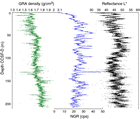
Unit I consists of unlithified foraminifer-rich, very fine to fine-grained wackestone to packstone with a calcareous ooze matrix. Thick (30–100 cm) to very thick (>100 cm) intervals defined by color changes ranging from light gray to grayish brown characterize this unit (Figure F3). Color changes are well documented in reflectance spectrometry, which also shows higher color variability than was macroscopically detected. The darker intervals show higher natural gamma radiation (NGR) counts per second and lower lightness (L*) values than the lighter intervals.
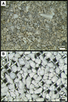
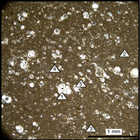
Throughout Unit I, well-preserved planktonic foraminifers are abundant and benthic foraminifers are common. Mollusk fragments, pteropods, echinoid fragments, and dark brown organic matter particles are present to common (Figure F4A). Cold-water coral remains occur at 359-U1467C-2H-3, 38 and 45–47 cm. Smear slide analysis shows that coccoliths, aragonite needles, tunicates, silicoflagellates, and sponge spicules are abundant in the finest fraction and that clay minerals and organic matter, although rare, do occur in slightly higher concentrations in the darker intervals. Bioturbation is common to intense in the darker intervals and is often represented by color mottling. Burrows contain higher concentrations of organic matter (black grains) and commonly coarser material. Contacts between the darker and lighter intervals are gradational.
Unit II
- Intervals: 359-U1467B-14H-5, 60 cm, to 25H-1, 103 cm; 359-U1467C-13H-2, 0 cm, through 22H-CC; 359-U1467D-12H-6, 34 cm, through 22H-CC
- Depths: Hole U1467B = 116.20–215.43 mbsf; Hole U1467C = 112.70 to >199.100 mbsf; Hole U1467D = 104.34 mbsf to >201.37 mbsf
The Unit I/II boundary is characterized by a transition from unlithified wackestone to interlayered unlithified and partially lithified, planktonic foraminifer-rich wackestone to mudstone (110–214.75 msbf). Components are abundant planktonic foraminifers, common benthic foraminifers, and an admixture of mollusk fragments, pteropods, and dark organic matter particles. The matrix consists of calcareous nannoplankton, tunicate spicules, sponge spicules, and aragonite needles. Celestine is also common as nodules and layers up to 3 cm thick and as fragments and crystals in the fine fraction (Figure F5).
Thick (30–100 cm) to very thick (>100 cm) cycles of minor color changes from light gray-brown to grayish brown are present throughout the unit. Downhole, however, color cycles become less distinct with partial lithification. Corresponding to the increasing lithification is the occurrence of a celestine layer in interval 359-U1467B-23H-5, 52–60 cm (197.42–197.50 mbsf), and occasional celestine nodules in Cores 359-U1467B-23H through 25H and Section 359-U1467D-27H-2 (Figure F5).
Unit III
The Unit II/III boundary was placed at a transition from the interlayered unlithified and partially lithified Unit II to the partially lithified wackestone of Unit III. Partially lithified wackestone to mudstone occurs at the top of Unit III (Cores 359-U1467B-25H through 30H), and wackestone forms the dominant lithology for the remainder of this unit. This unit’s fine-grained sediments are characterized by thick (30–100 cm) to very thick (>100 cm) cycles of faint color changes from light gray to light olive-gray and light brownish gray.
Major components of this unit are planktonic foraminifers; echinoid spines and sponge spicules are common, but benthic foraminifers are rare. The matrix of the deposits consists of calcareous nannoplankton. Preservation of skeletal components is very poor because of pervasive crystal overgrowth (Figure F4B). Celestine nodules and fragments are common, as well as bioclasts and particulate organic matter. Bivalve fragments usually occur as molds. Bioturbation is common, with Thalassinoides, Planolites, Palaeophycus, and possibly Zoophycos present to common. A slightly higher degree of bioturbation was observed in the darker intervals.
Unit IV
The Unit III/IV boundary was placed at a transition from partially lithified wackestone to more competent and lithified very fine to medium-grained wackestone to packstone. As in the overlying units, planktonic foraminifers are abundant and black grains (organic fragments) are present. The fine fraction consists of planktonic foraminiferal fine-grained wackestone with benthic foraminifers and abundant silt-sized bioclasts (Figure F6). Organic matter is present, and apatite is a minor component. Planktonic foraminifers occur in a micritic matrix and display calcite overgrowth. The major porosity type is interparticle, and the minor is moldic.
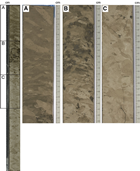
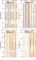
Similar to the units above, Unit IV is characterized by medium (10–30 cm) to very thick (>100 cm) cycles of slight changes in color from light gray to light brownish gray and pale yellow, with gradational and commonly bioturbated contacts between the intervals with different colors (Figure F7A–F7C). In contrast to the overlying units, Unit IV preserves a higher degree of bioturbation and includes common Thalassinoides, Planolites, Zoophycos, Chondrites, and Palaeophycus. Burrows are commonly infilled with coarser grained packstone and bear lower concentrations of organic matter (Figure F7). This unit displays more intense drilling disturbance (fragmentation and biscuits), especially in the lighter layers.
Unit V
- Intervals: 359-U1467B-65X-CC to 77X-1, 0 cm; 359-U1467C-24X-1, 0 cm, to 27X-2, 44 cm
- Depths: Hole U1467B = 498.50–607.50 mbsf; Hole U1467C = <578.60–609.5 mbsf
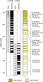
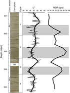
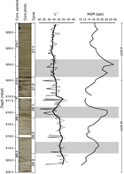
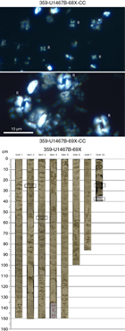
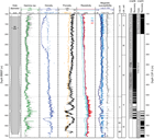
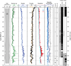
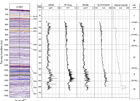
The Unit IV/V boundary is at a facies change to sediments with distinct light and dark alterations. Lighter intervals form 25%–50% of the cores, and downhole, the thickness and number of dark intervals decrease (Figure F8). Deposits are fine-grained planktonic foraminifer-rich wackestone. Other components are benthic foraminifers and fragments of organic matter. Bioturbation is more extensive within this unit than in overlying units, with common to abundant Thalassinoides, Planolites, Zoophycos, Chondrites, and Palaeophycus. Light intervals dominate this unit, and dark packages are between 1 and 30 cm thick. The darker intervals have lower L* values and a characteristic inverse relation to NGR values. This relation persists even in changes that are macroscopically marginally visible (e.g., Cycle 1: Core 359-U1467B-66X) (Figures F9, F10). There is also a larger scale increase in L* values and decrease in NGR values downhole than those observed in the overlying units, indicating an overall lightening of this unit.
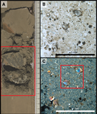
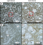
Petrographic analysis of the light (70X-1, 17–20 cm; 539.8 mbsf) and dark (70X-1, 101–104 cm; 540.6 mbsf) intervals demonstrates differences in components, texture, cementation, and organic matter content. Lighter intervals are very fine grained wackestone to packstone with abundant planktonic foraminifers and silt-sized bioclasts (Figure F11A–F11B). Planktonic foraminifers preserve their original morphology, and their internal pore spaces are partially infilled by dogtooth calcite cements. The matrix in lighter intervals consists of partially recrystallized micrite to microsparite. In contrast, darker intervals (Figure F11C–F11D) are very fine grained planktonic foraminiferal wackestone with minor to absent silt-sized bioclasts. The planktonic foraminifers are slightly compacted, and cements are absent in their pore space. The matrix is composed of micrite with abundant clay- to silt-sized organic matter remains. A crushed sea urchin was found in interval 359-U1467B-69X-2, 117–119 cm (~531.5 mbsf).
Unit VI
- Intervals: 359-U1467B-77X-1, 0 cm, through 77X-CC; 359-U1467C-27X-2, 44 cm, through 37X-CC
- Depths: Hole U1467B = 607.50 to >617.41 mbsf; Hole U1467C = 609.50–707.92 mbsf
The Unit V/VI boundary is at a sharp facies change from the succession of light–dark alternation to white wackestone to packstone, with very few pale gray to gray intervals (Figure F10). The limit of Units V and VI is well imaged in L* and NGR analyses. The change to lighter rocks is accompanied by a maximum NGR value of 26 counts/s that decreases to 24 counts/s in Core 359-U1467C-27X and to 18 counts/s farther downhole.
Unit VI has components similar to those in the overlying unit. Petrographic analysis shows that deposits are planktonic foraminiferal fine-grained wackestone to packstone with abundant silt-sized bioclasts, benthic foraminifers (Amphistegina), and echinoid spines. Components occur in a partially recrystallized micritic matrix that occasionally infills the intraparticle porosity of the planktonic foraminifers. Apatite crystals and organic matter rarely occur.
Discussion
The sedimentary succession of the distal portion of the Kardiva Channel drifts consists of a monotonous series of foraminiferal wackestone and packstone with increasing downhole lithification. The major sedimentary variability is color change with a leitmotif of light–dark cyclicity. Compared to the dark intervals, light packages appear more bioturbated and are depleted in organic matter. Dark intervals are most likely the result of decreased carbonate shedding from the adjacent carbonate banks during sea level lowstands and greater preservation of organic material during lower oxygenation conditions in the overlying water column (Schlager et al., 1994; Betzler et al., 2013).
Color changes may also be associated with fluctuations in productivity due to changes in oxygenation of the water column, as previously identified by Boersma and Mikkelsen (1990) at Ocean Drilling Program (ODP) Site 714, located approximately 64 km east of Site U1467. Boersma and Mikkelsen (1990) also interpreted the darker intervals as periods of higher productivity in a low-oxygenated depositional environment. At ODP Site 715, dark intervals are characterized by the presence of bolivinids that represent oxygen minima (Douglas and Heitman, 1979; Poag and Low, 1985). This characterization is also consistent with results in Biostratigraphy.
The hypothesis that dark and light intervals are associated with fluctuations in productivity due to changes in oxygenation in the water column and greater preservation of organic material during lower oxygenation conditions is supported by the spectral NGR data at Site U1467. The inverse relation between L* and NGR (Figures F9, F10) implies that darker intervals are generally more radiogenic, with uranium being retained with relatively higher concentrations of organic matter (Klinkhammer and Palmer, 1991). This retention implies high productivity in the overlying water column and the possibility of low-oxygen bottom conditions. In contrast, lighter intervals show lower NGR values, indicating they have comparatively less organic material than darker intervals and most likely higher shallow-water carbonate platform derived input.
Biostratigraphy
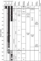
A ~700 m thick sediment succession spanning the Pleistocene to the middle Miocene was cored in four holes at Site U1467. The shipboard paleontologists examined samples from Cores 359-U1467A-1H through 4H (0–32 mbsf), 359-U1467B-4H through 77X (22.5–617.2 mbsf), and 359-U1467C-24X through 37X (578.6–714 mbsf) (Figure F12). For biostratigraphic discussion, the succession was divided into three intervals (A–C), as described in Age model.
Interval A was recovered in Cores 359-U1467A-1H through 4H and 359-U1467B-1H through 15H and extends from the surface to ~130 mbsf. It provides a continuous expanded record of Quaternary and late Pliocene sedimentation in the equatorial Indian Ocean. This interval was recovered in three holes (U1467A, U1467B, and U1467C), which were combined to provide a splice record (Figure F12; see Stratigraphic correlation and sedimentation rates). Throughout this interval, planktonic foraminifers are well preserved; benthic foraminifers, ostracods, and calcareous nannofossils are well preserved at the top but moderately well preserved from Core 359-U1467B-5H downward.
Interval B was recovered in Cores 359-U1467B-16H through 69X and extends from ~130 to 540 mbsf; it comprises the early Pliocene and much of the late Miocene. Preservation throughout this thick interval is poor to moderate for all microfossils, except in Core 69X where very well preserved nannofossils were recovered from a few darker layers.
Interval C was recovered in Cores 359-U1467B-70X through 77X and 359-U1467C-24X through 37X and extends from 540 to 714 mbsf; it comprises the earlier part of the late Miocene and the later part of the middle Miocene. In the upper part of this interval, all groups of calcareous microfossils are rare and poorly preserved. Preservation improves downcore and in the lower part of the interval is moderate to good.
Mudline core top samples were collected from Holes U1467A–U1467C, and portions of these samples were stained with Rose Bengal (1 g/L) to confirm the presence of living ostracods and benthic foraminifers. Mudline samples are rich in pteropod fragments, planktonic and benthic foraminifers, nannofossils, radiolarians, and ostracods.
Age model
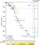
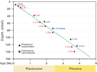
The biostratigraphic events recognized at this site are listed in Table T2. The biozonation inferred from biostratigraphic data and paleoenvironmental interpretations are shown in Figure F12. An age-depth plot is given in Figure F13 and allows direct comparison of the data and calculation of average sedimentation rates.
Table T2. Biostratigraphic events, Site U1467. Download table in .csv format.
Interval A is a succession of well-constrained events with reasonably good agreement between planktonic foraminifers and nannofossils. However, much of the interval shows a consistent offset between ages inferred from calcareous nannofossil events and planktonic foraminifers, with planktonic foraminifers suggesting ages about 0.5 My older than the calcareous nannofossils (Figure F14). This pattern was also seen in this interval at Sites U1465 and U1466, so possibly the age calibrations of these events need revision, at least for this area. The inferred average sedimentation rate is ~3.4 cm/ky.
In Interval B, fewer events were recognized, particularly in planktonic foraminifers, but they mostly agree well with the nannofossil events. The age of the top of this interval is well constrained by a set of reliable mid-Pliocene datums, and the age of the base is constrained by two reliable nannofossil datums (the first occurrence [FO] of Discoaster quinqueramus and the base of the small Reticulofenestra event) (Figure F15). The intervening events are less reliable, but they fall on a straight line correlation between these endpoints, implying an average sedimentation rate of ~7.9 cm/ky. This rate is more than twice the average sedimentation rate obtained for the Pliocene–Pleistocene (Figure F13).
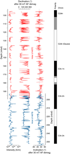
Magnetostratigraphy shows reliable results from ~100 to 200 mbsf (see Paleomagnetism). Data commence with a long reversed interval that, when compared to the biostratigraphic data, was confidently identified as the Gauss magnetochron, C2Ar. Following from this, a succession of subchrons was identified within Chron C3n. These data have been added to the age-depth plot (Figure F13) and fit very well with the paleontological data. Magnetostratigraphy and biostratigraphy independently give the same sedimentation rate for this interval.
Interval C is less clearly constrained; however, in the lower part of the section, assemblages of both nannofossils and planktonic foraminifers are sufficiently well preserved to state with confidence that three events do not occur in the section: (1) the last common occurrence (LCO) of the nannofossil Cyclicargolithus floridanus (13.28 Ma); (2) the last occurrence (LO) of the planktonic foraminifer Fohsella fohsi (13.41 Ma), and (3) the LO of the nannofossil Sphenolithus heteromorphus (13.53 Ma). These three events are well developed at Site U1466, so we are confident that the base of the section is younger than 13.3–13.4 Ma. This age gives a minimum mean sedimentation rate through this interval of 3.8 cm/ky. Three events were recognized in the interval, all of which lie near this trend: the LOs of Paragloborotalia mayeri, F. fohsi, and Coronocyclus nitescens. Therefore, even though many standard zonal marker events were not recognized in this interval, a clear age model was established (Figure F13).
Calcareous nannofossils
Calcareous nannofossils are present throughout the interval recovered at Site U1467, although with variable preservation. Smear slides were examined from all core catcher samples, and assemblage data are presented in Table T3. In addition, extra samples from core sections were examined to better constrain biostratigraphic datums.
Table T3. Nannofossil range chart, Holes U1467A, U1467B, and U1467C. Download table in .csv format.
Interval A (Cores 359-U1467A-1H through 4H and 359-U1467B-1H through 15H)
Nannofossil preservation is very good in the late Quaternary, with essentially pristine assemblages from the top to about 50 mbsf (nannofossils examined in Cores 359-U1467A-1H through 4H and 359-U1467B-4H). Below this depth, nannofossils are still abundant but show varying degrees of overgrowth. Most taxa could still easily be identified, but the overgrowth strongly affected discoasters, which were also rare in this interval, so some events were not recognized. Otherwise, a full set of marker events was recorded and indicates a rather uniform sedimentation rate (Figure F13).
The FO of Emiliania huxleyi was located by light microscopy (Table T3) and confirmed by scanning electron microscope (SEM). It is present in Samples 359-U1467A-1H-CC and 359-U1467B-1H-CC but absent in Samples 359-U1467A-2H-CC and 359-U1467B-2H-CC. The LO of Pseudoemiliania huxleyi was only identified by light microscopy; however, the species occurrence decreases toward its LO. The poorer preservation of samples in the early Pleistocene meant that many specimens of Gephyrocapsa lumina lacked clear bridges, which made identification of the base of the small Gephyrocapsa event/LO of G. lumina problematic. The LO of Calcidiscus macintyrei was also problematic because specimens are very rare. However, the LO of this large species (>10 µm) was clearly identified using low magnification. The successive FOs of Discoaster brouweri and Discoaster pentaradiatus were well marked. The Discoaster triradiatus acme is only weakly developed in these samples but was seen in the latter part of Zone NN18 (Sample 359-U1467A-8H-CC). Discoaster variabilis, Discoaster surculus, and Discoaster tamalis are too rare to allow identification of their LOs. The LO of Sphenolithus abies is clearly marked with common to abundant specimens occurring below the LO at 127 mbsf. The LO of Reticulofenestra pseudoumbilicus occurs slightly below this depth, confirming the age placement.
Interval B (Cores 359-U1467B-16H through 69X)
Interval B is predominantly a long sequence of assemblages with very similar nannofossils. Nannofossils are normally abundant with poor to moderate preservation due to overgrowth. Larger coccoliths and nannoliths are especially affected by this overgrowth, with discoaster specimens often very difficult to identify to species level. Ceratoliths are also strongly affected by overgrowth. A few specimens of Nicklithus were identified, but no specimens of Ceratolithus or Amaurolithus were found. Similarly, only one specimen of Orthorhabdus was identified, and no Minylitha. As a result, events based on these taxa could not be identified. D. quinqueramus is common, and its FO and LO were confidently placed, but subdivision into D. quinqueramus and Discoaster berggrenii was not possible. The intervening events based on the FO and LO of Nicklithus amplificus were only tentatively identified, but their placement agrees well with the overall age model.
A marked episode within the late Miocene nannofossil record is provided by the abrupt disappearance of large (>7 µm) R. pseudoumbilicus specimens followed by an interval of dominance of very small reticulofenestrids (dominantly <3 µm). This event was first described in the western Indian Ocean by Rio et al. (1990) and Young (1990) and has since been shown to be a useful globally synchronous event (e.g., Backman et al., 2012) occurring near the top of Magnetochron C4An and currently placed at 8.79 Ma. The event is well marked at Site U1467, occurring between Samples 359-U1467B-68X-CC and 69X-2, 25 cm. Several dark levels occur in Core 69X and have very well preserved nannofossils, including exceptionally well preserved discoasters.
Interval C (Cores 359-U1467B-70X through 77X and 359-U1467C-24X through 37X)
Interval C starts just below the small Reticulofenestra event and lies clearly within Zone NN10. It ends in Zone NN6, as indicated by the occurrence of C. nitescens and absence of C. floridanus and S. heteromorphus. However, no events can be recognized through most of this interval, and Zones NN9–NN7 cannot be distinguished. More specifically, no specimens were observed of Catinaster calyculus, Catinaster coalitus, Discoaster hamatus, Discoaster bollii, or Minylitha convallis, probably because of poor preservation in the upper part of the interval. For example, we observed heavily overgrown five-rayed discoasters in Sample 359-U1467B-73R-1, 22 cm (569.92 mbsf), but we could not discriminate whether they belong to D. hamatus. The LO of C. nitescens is well marked; it is consistently present below Sample 359-U1467C-34X-CC but absent above.
Planktonic foraminifers
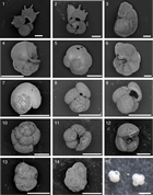
Planktonic foraminifers were examined in all core catcher samples from Holes U1467A (4 samples; Table T4), U1467B (77 samples; Table T5), and U1467C (14 samples; Table T6), although we only used Holes U1467B and U1467C to determine the placement of the biozone boundaries and to construct the age model. The mudline sample recovered in Hole U1467A was also examined. Planktonic foraminiferal stratigraphy shows continuous sedimentation from the Pleistocene to the middle Miocene. Foraminifer preservation is good in the samples from Holes U1467A and Samples 359-U1467B-1H-CC to 16H-CC. Below Sample 16H-CC (~138 mbsf), preservation in Holes U1467B and U1467C ranges from moderate to very poor. Figure F16 shows the main species of planktonic foraminifers used for biozonation and their preservation.
Table T4. Planktonic foraminifer range chart, Hole U1467A. Download table in .csv format.
Table T5. Planktonic foraminifer range chart, Hole U1467B. Download table in .csv format.
Table T6. Planktonic foraminifer range chart, Hole U1467C. Download table in .csv format.
Interval A (Cores 359-U1467B-1H through 15H)
Interval A includes the Pleistocene and late Pliocene sequence. Planktonic foraminifers are abundant with good to very good preservation. Three Pleistocene bioevents were identified: the LO of Globigerinoides ruber pink (0.12 Ma) between Samples 359-U1467B-1H-CC and 2H-CC (~3.5–12.5 mbsf), the LO of Globigerinoides fistulosus (1.88 Ma) between Samples 6H-CC and 7H-CC (~51–61 mbsf), and the LO of Globorotalia limbata between Samples 8H-CC and 9H-CC (~70–79 mbsf). Within the Pliocene, we identified the LO of Dentoglobigerina altispira (3.47 Ma) between Samples 12H-CC and 13H-CC (~100–110 mbsf) and the LO of Globorotalia margaritae (3.85 Ma) between Samples 14H-CC and 15H-CC (~119–128 mbsf).
Interval B (Cores 359-U1467B-16H through 69X)
Interval B encompasses the early Pliocene and the upper part of the middle Miocene. Planktonic foraminifers are generally abundant, and preservation mainly ranges from poor to moderate. Two late Miocene bioevents were identified: the LO of Globoquadrina dehiscens (5.92 Ma) between Samples 359-U1467B-37H-CC and 38H-CC (~338–343 mbsf) and the LO of Globorotalia lenguaensis (6.13 Ma) between Samples 43H-CC and 44H-CC (~369–381 mbsf). The LO of Sphaeroidinellopsis seminulina (3.59 Ma) between Samples 12H-CC and 13H-CC and the FO of Globorotalia tumida (5.57 Ma) between Samples 29H-CC and 30H-CC used to establish the PL4/PL3 and PL1/M14 boundaries were also used to determine zonal boundaries.
Interval C (Cores 359-U1467B-70X through 77X and 359-U1467C-24X through 37X)
In Interval C, planktonic foraminifers are abundant but show moderate to very poor preservation. We identified the LO of P. mayeri (10.46 Ma) in Hole U1467B between Samples 359-U1467B-74H-CC and 75H-CC (~581–593 mbsf) and in Hole U1467C between Samples 359-U1467C-25H-CC and 26H-CC (~590–602 mbsf). The small offset in depth is probably due to the low resolution of the study, given that we only used core catchers, but we cannot rule out a small offset between the depths calculated for both holes at this stage. The LO of F. fohsi (13.41 Ma) was tentatively identified between Samples 359-U1467C-28X-CC and 29X-CC (~620–634 mbsf). The LO of F. fohsi is displayed with a large error bar in Figure F13. Placement of the LO of this species is rather difficult because only few small specimens are present in this interval. The occurrence of F. fohsi in Sample 359-U1467C-37X-CC indicates that the bottom of Hole U1467C is younger than 13.41 Ma. Additionally, we used the FO of Neogloboquadrina acostaensis (9.83 Ma) between Samples 359-U1467B-69X-CC and 70X-CC to place the M13/M12 zonal boundary.
Benthic foraminifers
Site U1467 provides a middle Miocene to Pleistocene record of outer neritic to middle bathyal benthic foraminiferal assemblages. Twelve Pleistocene samples were investigated from Holes U1467A and U1467B, and four Pliocene samples were investigated from Hole U1467B. Thirteen late Miocene samples were investigated from Holes U1467B and U1467C, as well as four middle Miocene samples from Hole U1467C.
Changes in benthic faunas from the middle to late Miocene sections in Holes U1467B and U1467C may suggest the initiation of lower oxygen conditions during primary productivity pulses. An increase in abundance of the benthic foraminifer genus Bolivina is observed in Sample 359-U1467B-77X-CC and Samples 359-U1467C-26X-CC to 32X-CC. Previous work on benthic foraminifers from ODP Site 714 in the north central Indian Ocean by Boersma (1990) shows similar benthic assemblages. Boersma’s Site 714 study used bolivinids as tracers of low-oxygen waters or bottom conditions related to the presence of a distinct onset around 10 Ma. Bolivinid abundance at Site 714 was used to recognize times of high primary production in the South Indian upwelling zone.
Interval A (Cores 359-U1467B-1H through 15H)
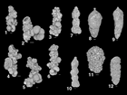
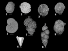
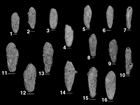
Benthic foraminifers are abundant in the Pleistocene and late Pliocene sequence intervals and show good to very good preservation. The assemblage is dominated by very large agglutinated benthic foraminifers (Reophax sp.), Textularia sp., Uvigerina hispida, Uvigerina proboscidea, Uvigerina sp., and small miliolids. Ostracods are also abundant throughout this interval, with good to very good preservation. Fish teeth are common, and the samples are also rich in pteropods with whole shells and fragments (Figures F17, F18).
Interval B (Cores 359-U1467B-16H through 69X)
Throughout this Pliocene and upper part of the middle Miocene interval, benthic foraminifers are abundant and record outer neritic to middle bathyal paleodepths. Benthic foraminiferal preservation in Holes U1467B and U1467C ranges from moderate to very poor below Sample 359-U1467B-16H-CC (~138 mbsf) (Table T7). Uvigerina sp. is common throughout this succession as well. Benthic foraminifers are accompanied by siliceous material (sponge spicules, diatoms, and radiolarians) throughout this succession.
Table T7. Benthic foraminifer range chart, Holes U1467A, U1467B, and U1467C. Download table in .csv format.
Interval C (Cores 359-U1467B-70X through 77X and 359-U1467C-24X through 37X)
In Interval C, benthic foraminifers are abundant but show moderate to very poor preservation. Bolivinids become common in this interval, with both smooth flat and crenulated bolivinids present (Figure F19). Siphonina pozonensis is also common in this interval, indicating an outer neritic to middle bathyal paleodepth.
Ostracods
A preliminary examination of ostracods at Site U1467 was conducted in selected core catcher samples from Holes U1467A–U1467C (Table T8). In Hole U1467A, ostracods were examined in Samples 359-U1467A-1H-CC to 4H-CC (Middle to Late Pleistocene) and in the mudline (sediment/water interface) sample. In Hole U1467B, ostracods were examined in Samples 359-U1467B-1H-CC to 8H-CC (early to Late Pleistocene); 12H-CC, 17H-CC, 22H-CC, 27H-CC, and 28H-CC (Pliocene); and 32H-CC, 37H-CC, 42F-CC, 47F-CC, 53F-CC, 58F-CC, 63X-CC, and 68X-CC (late Miocene). In Hole U1467C, ostracods were examined in Sample 359-U1467C-33X-CC (middle Miocene).
Table T8. Ostracod range chart, Holes U1467A, U1467B, and U1467C. Download table in .csv format.
Pleistocene ostracod fauna
Ostracods are most abundant in the Pleistocene section of Site U1467 and show very good to good preservation. This interval is divided into a mid- to Late Pleistocene assemblage and an early Pleistocene assemblage. The mid- to Late Pleistocene group is dominated by the ostracod genera Bradleya, Cytherella, Krithe, Argilloecia, and Cytheropteron and represents an outer neritic to upper bathyal paleoenvironment. The early Pleistocene assemblage is dominated by Bradleya, Mutilus, Argilloecia, Xestoleberis, Krithe, Bairdiids, and Loxocorniculum and is interpreted as representing middle to outer neritic conditions.
Pliocene ostracod fauna
Ostracods are less abundant in the Pliocene section of Site U1467 and show moderate to poor preservation. The Pliocene assemblage is characterized by Bradleya and Cytherella as the major components, with Leptocythere, Loxocorniculum, Krithella?, Bairdiids, Cytheropteron, and Caudites as secondary components. This assemblage is interpreted as representing middle to inner neritic conditions.
Miocene ostracod fauna
Ostracods are common throughout the Miocene section, and their preservation is generally poor to moderate. The Miocene assemblage is dominated by Bradleya and Cytherella, with Cytheropteron, Xestoleberis, and Krithe as secondary components. This assemblage represents an outer neritic to upper bathyal paleoenvironment.
To assess the variability of bottom water ventilation during the late Miocene to the Pleistocene at Site U1467, the stratigraphic distribution of infaunal taxa (Krithe, Argilloecia, Australoecia, Macrocyprina, Pontocypris, etc.) was investigated. The infaunal lifestyle of these taxa has been inferred from the smooth elongate morphology of their carapace, as is the case for Krithe (e.g., Coles et al., 1994; Majoran and Agrenius, 1995; Alvarez Zarikian et al., 2009; Aiello et al., 2015). Infaunal ostracod taxa are generally associated with higher organic matter flux to the seafloor, poor ventilation of the bottom water, and thus low dissolved oxygen conditions, whereas higher abundances of epifaunal taxa are more characteristic of oligotrophic environments (Alvarez Zarikian, 2015). Based on the preliminary data on the distribution of infaunal ostracod taxa at Site U1467, higher surface productivity and lower oxygen conditions can be inferred for the Pleistocene and during two intervals in the late Miocene.
Radiolarians
A total of 4 core catcher samples from Hole U1467A, 42 core catcher samples from Hole U1467B, and 7 core catcher samples from Hole U1467C were prepared for radiolarian analysis. We found radiolarians in 2 core catcher samples from Hole U1467A (Samples 1H-CC and 3H-CC) and 11 core catcher samples from Hole U1467B (Samples 1H-CC, 2H-CC, 23H-CC, 24H-CC, 25H-CC, 27H-CC, 59F-CC, 61F-CC, 65F-CC, 69X-CC, and 73X-CC). Other siliceous microfossils such as sponge spicules and diatoms show intervals of higher abundance in Hole U1467B. Siliceous microfossils increase in abundance from Sample 359-U1467B-21H-CC, peak in Sample 23H-CC, and are absent downcore from Sample 33H-CC. Siliceous microfossils increase again from Sample 58F-CC, with maximum abundances in Samples 61F-CC and 73X-CC, although the interval between Samples 65X-CC and 71X-CC is almost barren of siliceous microfossils. Below Sample 75X-CC, no siliceous microfossils were found. Almost all of the encountered radiolarians belong to the Zygocircus productus (Hertwig) group. No radiolarians were found in Hole U1467C core catcher samples.
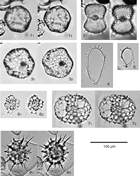
Additionally, a total of 69 species were identified and counted from the mudline sample of Hole U1467B. The most common species is Tetrapyle octacantha Müller group, a warm-water subtropical species. Didymocyrtis tetrathalamus (Haeckel) and Larcopyle butschlii (Dreyer), which are warm-water and intermediate-water species, respectively, are also common in the mudline sample (Figure F20). Five daily sea-surface water samples were also collected at Site U1467 for the examination of modern planktonic organisms, including radiolarians (Young et al., 2017). In these samples, 21 radiolarian species were observed including warm-water species, such as Acanthodesmia viniculata Müller, D. tetrathalamus (Haeckel), Lophophaena variabilis (Popofsky), and T. octacantha Müller group, as well as tropical species, such as Z. productus (Hertwig) group.
Geochemistry
Interstitial water chemistry
Interstitial water (IW) samples were collected by squeezing whole-round samples at a rate of one per core (recovery permitting). Including mudline samples taken from both holes, 5 IW samples were taken from Hole U1467A and 105 were taken from Hole U1467B. In addition, Rhizon samples over the upper ~40 m of Hole U1467B were taken at a rate of two per section. Furthermore, 8 IW samples were taken from Hole U1467C from 588 mbsf to the bottom of the hole. We describe mainly the results from Holes U1467B and U1467C.
The applied squeezing pressure ranged from 8,000 to 30,000 psi, and the amounts of extracted IW ranged between 30 and 50 cm3. The 5, 10, and 15 cm whole-round cores were taken above 57 mbsf (Sections 359-U1467B-1H-4 through 7H-4), from ~57 to ~386 mbsf (Sections 8H-4 through 45H-4), and below 386 mbsf (Sections 47H-2 through 359-U1467C-36X-4), respectively. Splits of IW samples were preserved for shore-based analyses of carbon, oxygen, sulfur, calcium, magnesium, and strontium isotopes. Concentrations of all species measured are presented in Table T9.
Table T9. Interstitial water chemistry, Site U1467. Download table in .csv format.
Chloride, bromide, and salinity
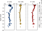
Concentrations of Cl– measured using titration with AgNO3 are higher (~560 to ~565 mM) at shallow depths (~37.95 mbsf) than the seawater value (~550 mM) and increase to 572.3 mM at 85.4 mbsf (Figure F21; Table T9). Concentrations then decrease to a minimum of 549.5 mM at 239 mbsf. Below this depth, Cl– remains relatively constant with values around 558 mM at 700 mbsf and small peaks around 500 and 600 mbsf. Br– increases slightly from 0.86 mM at the surface to around 0.88 mM at 100 mbsf and decreases below this depth to 0.82 mM at 700 mbsf. Salinity is mostly stable at 35, but between 57 and 153 mbsf, salinity is higher (35.5), which corresponds to the peak of Cl–.
Sodium and potassium
Concentrations of Na+ and K+ show similar trends throughout the cores and mirror Cl– trends, although Cl– trends are more clear (Figure F21; Table T9). Na+ in squeezed pore water samples increases from 484 to 494 mM in the upper 80 mbsf, decreases to 475 mM at 239 mbsf, and remains stable below this depth at around 478 mM. Potassium is higher at the surface (~10.79 mM), remains stable to 80 mbsf, decreases to 9.6 mM at 239 mbsf, and remains stable again from 300 to 700 mbsf with values around 9.8 mM.
Alkalinity, pH, dissolved sulfate, and ammonium
Alkalinity shows larger variation between 2.36 and 8.97 mM, values that are higher than those observed at Sites U1465 and U1466. Alkalinity is stable at around 2.8 mM in the upper 47.5 mbsf, increases to a maximum of 8.97 mM at 201 mbsf, and then gradually decreases to 2.83 mM at 700 mbsf, which is a value similar to the concentration found in the surface sediment sample (Figure F22; Table T9). The pH of Rhizon samples is higher (~0.2) than that of squeezed IW samples, although data for both are stable in the upper 40 m. The pH of squeezed IW samples (~7.8) is stable to 85 mbsf, plateaus at 7.9 between 100 and 200 mbsf, and subsequently decreases to 700 mbsf, although the data are relatively scattered.
A depletion of SO42– from 29 to 23 mM occurs between 30 and 260 mbsf. Below this depth, concentrations increase gradually throughout the remainder of the core to 26.5 mM. The SO42– profile negatively correlates (R2 = 0.49) with that of alkalinity, and both peaks are around 200 mbsf. Similarly, SO42– is strongly negatively correlated to ammonium (NH4+) (R2 = 0.82). Concentrations of NH4+ increase linearly from approximately 170 µM at 30 mbsf to approximately 1380 µM at 260 mbsf and then decrease linearly to 442 µM at 613 mbsf.
Calcium, magnesium, strontium, and lithium
Concentrations of Ca2+ increase linearly over the upper 200 mbsf from a value close to that of seawater (~11 mM) to 18 mM. Below 200 mbsf, concentrations remain approximately stable. This trend mirrors the Mg2+ profile, which declines steadily from 56 to 45 mM over the upper 200 mbsf, with stable values below (Figure F23; Table T9). Concentrations of Mg2+ and Ca2+ are strongly negatively correlated (R2 = 0.88). As a result of both the increase in Ca2+ and decrease in Mg2+, the Mg2+/Ca2+ ratios in the pore fluids steadily decrease from values near seawater (5.1 mol/mol) at the surface to approximately 2.5 mol/mol from 200 mbsf to the bottom of Hole U1467C (Figure F24).
Concentrations of Sr2+ increase sharply from less than 120 µM to around 500 µM from 35 to 100 mbsf. Pore fluid Sr2+ concentrations do not exceed 500 µM, and those at Site U1467 are higher than those at Sites U1466 and U1465 (see Figure F33 in the Site U1466 chapter [Betzler et al., 2017c]). Concentrations of Sr2+ then become stable at ~600 µM between 100 and ~400 mbsf before decreasing to 261 µM at the bottom of Hole U1467C (700 mbsf). On the other hand, Li+ concentrations are somewhat similar, with a stable interval between 100 and 500 mbsf, but have a negative trend compared to those of Sr2+ from 500 mbsf to the bottom of the hole (700 mbsf). Lithium is constant at approximately 20 µM from the surface to around 500 mbsf and then increases to 32 µM at the bottom of the hole, the interval in which Sr2+ decreases. Sr2+/Ca2+ ratios in the pore fluid also increase sharply in the upper 35–100 mbsf and gradually decrease to 700 mbsf. This profile differs from that of Mg2+/Ca2+, which decreases over the same intervals. Although Ca2+/Cl– reflects the profile of Ca2+, Mg2+/Cl– is almost stable throughout the holes because of similar decreasing trends in both concentrations between 100 and 230 mbsf.
Iron, barium, boron, and silicon
Iron, boron, and barium concentrations are almost in the same range as those found at Site U1466, whereas those of silicon are higher (Figure F25; Table T9).
Iron is mostly less than 2 µM and stable throughout Holes U1467B and U1467C with some scattered values found between 300 and 500 mbsf.
Boron ranges between 420 and 571 µM, increasing very slightly from 420 µM at the surface to 570 µM at 324 mbsf and then decreasing to values similar to those found at the surface.
Barium ranges from 0.22 to 0.76 µM and does not show any systematic trend throughout Holes U1467B and U1467C.
Silicon exhibits multiple localized maxima and minima throughout the holes. Silicon initially increases from around 130 to 710 µM between 100 and 200 mbsf, parallel to an increase in alkalinity (Figure F22). Below 200 mbsf, Si concentrations remain higher between 540 and 920 µM with some variations. This concentration is roughly twice that found at Site U1466.
Bulk sediment geochemistry
Calcium carbonate
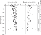
Carbonate content was determined at a rate of one sample per section, and carbon was determined at a rate of one sample per core. In total, 260 samples were analyzed. Because dolomite concentrations are very low (maximum = 2%) at Site U1467 compared to Site U1466, no correction is applied to carbonate contents. The range of carbonate content is between 70.5 and 95.6 wt%, and only a few samples exceed 95 wt%, with the exception of the data at 54.7 mbsf (106 wt%), which seems to be an error because no dolomite is found at this depth. This carbonate content is lower than that found at Site U1466, where the majority of the data falls between 85 and 99 wt% (Figure F26; Table T10). Carbonate content in the upper 50 mbsf increases slightly from 75 to 95 wt% with an average value of 83.8 wt%. Below this depth, carbonate content varies, whereas the mean content increases to 88.2 wt% from 50 to 700 mbsf.
Table T10. Carbon and nitrogen, Site U1467. Download table in .csv format.
Organic carbon
Total organic carbon concentration was measured on one sample per core and ranges between 0.0 and 4.0 wt% with the exception of four samples at 88.8, 112.1, 167.7 and 666.5 mbsf, which have more than 5 wt% organic carbon (Figure F26; Table T10). Several samples have calculated organic concentrations less than zero. This is an artifact of the inadequate method of determining the amount of organic carbon in carbonate-rich sediments (see Geochemistry in the Expedition 359 methods chapter [Betzler et al., 2017a]).
Total organic nitrogen is low, ranging from 0.09 to 0.18 wt%. As a result of the persistent negative percent carbonate, no attempt was made to calculate C:N.
X-ray diffraction
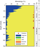
Mineralogy was determined at a rate of approximately one sample per core, with additional material supplied from the Sedimentology group. In the upper ~120 mbsf, the sediment consists of between 28% and 57% aragonite, with the remainder being composed of low-Mg calcite (LMC) and small amounts of high-Mg calcite (HMC) (Figure F27; Table T11). Below this depth, LMC predominates with an admixture of dolomite and celestine. However, celestine is only found between 163 and 393 mbsf. Below this interval, neither celestine nor dolomite was observed. Aragonite appears again from 500 to 610 mbsf with contents less than 23%. Quartz contents are less than 1% throughout Site U1467.
Table T11. XRD results, Site U1467. Download table in .csv format.
Major, minor, and trace element composition
Minor and trace element concentrations were measured on all IW squeezed samples from Holes U1467A–U1467C. The most important elements relevant to carbonate diagenesis (Sr, Mg, Fe, and Mn) are presented in Figure F28 as molar ratios relative to calcium. All data are presented in Table T12.
Table T12. Solids geochemistry, Site U1467. Download table in .csv format.
Strontium and magnesium
Bulk sediment Sr/Ca ratios are variable throughout the core, ranging from 0.4 to 6.1 mmol/mol, which is higher those found at Site U1466 (~4 mmol/mol). Ratios of Sr/Ca exceeding 5 mmol/mol were found between 100 and 200 mbsf and between 500 and 600 mbsf. On the other hand, Mg/Ca is higher and more variable above 200 mbsf with a mean value of 5.5 mmol/mol. There is a stable interval with values around 3.5 mmol/mol from 250 to 500 mbsf. Below this depth to the bottom of the hole, Mg/Ca increases to 6.0 mmol/mol.
Manganese and iron
Ratios of Mn/Ca are stable at around 35 µmol/mol throughout the core, whereas Fe/Ca is higher at the surface (approximately above 60 mbsf), as seen at Site U1466. The initial higher Fe/Ca ratios vary between 60 and 170 µmol/mol and remain constant, similar to Mn/Ca, at around 70 µmol/mol below 100 mbsf.
Volatile hydrocarbons
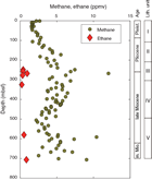
Samples for the analysis of methane, ethene, ethane, propene, and propane (headspace gases) were taken from cores from Holes U1467A–U1467C. These samples were generally taken from the top of Section 5 in each core when an IW sample was taken. Methane concentrations remain between 1.6 and 12.0 ppmv, increase slightly from the surface to 300 mbsf, and then remain mostly stable at around 5 ppmv with some scattering values (Figure F29; Table T13). Ethane is only present in measurable quantities (~1 ppmv) at 249–277, 324, 580, and 706 mbsf.
Table T13. Headspace hydrocarbons, Site U1467. Download table in .csv format.
Discussion
The geochemistry of the interstitial fluids from Site U1467 indicates that significant remineralization of organic material has occurred below 50 mbsf, as reflected by changes in SO42– and alkalinity. The sharp increase in alkalinity between 50 and 280 mbsf coincides with a decrease in SO42– concentrations over this range, although there is a small depth discrepancy between the maxima and minima of these two species. The odor of H2S was also noted upon core recovery and squeezing of whole-round samples, suggesting that bacterial sulfate reduction (BSR) probably accounts for the observed trend. Because large amounts of NH4+ are released during the decomposition of sedimentary organic matter, a negative correlation between SO42– and NH4+ is also related to the oxidation of organic matter. Comparing these data with data from ODP Site 716 (Shipboard Scientific Party, 1988), the overall concentrations of alkalinity are significantly greater in Hole U1467B. In addition, the SO42– profile in Hole 716A shows only minor decreases in SO42–.
Although Cl–, Na+, and K+ are generally thought of as conservative ions, an increasing trend in Cl– from the sediment surface to around 100 mbsf that may be related to the last glacial period when salinity was greater than today as a result of Northern Hemisphere glaciation. This trend was first noted in Deep Sea Drilling Project (DSDP) pore fluids by McDuff (1985), who assumed that chloride was 3.7% elevated at maximum glaciation based on model calculations using the stacked δ18O record of SPECMAP (Imbrie et al., 1984) for the interval from 0 to 0.8 Ma and reported a ~1.5% increase in Cl– in pore fluids from the northwest Pacific (DSDP Leg 86). The elevation of Cl– found from the surface (mudline) to 100 mbsf in Hole U1467B is ~2.7% higher, which is lower than the model (3.7% elevation), and suggests that diffusion has dampened the signal over time. Pore waters that are elevated in Cl– were shown to have higher δ18O values, thus enabling the δ18O of ocean water to be reconstructed (Schrag et al., 1996).
At Site U1467, aragonite concentrations remain relatively high (~60%) in the upper 50–100 mbsf (lithostratigraphic Unit I), similar to those at Site U1466, indicating possible input from adjacent platforms during changes in sea level. Sr2+ concentrations do not increase in the pore fluids over this interval, supporting the hypothesis that aragonite concentrations were not reduced by diagenesis in this depth range.
Below 50 mbsf in Hole U1467B, aragonite concentrations decrease to less than ~15% at 125 mbsf. This decrease could be a result of diminishing input of aragonite or more likely the dissolution of aragonite followed by precipitation of calcite. This latter idea is supported by the substantial increase in Sr2+ in the pore water, which is attributable to the exclusion of Sr2+ during the precipitation of calcite. Low (<10%) aragonite contents occur between 200 and 500 mbsf, and aragonite appears again from 500 to 613 mbsf. This aragonite interval corresponds to lithostratigraphic Unit V. Strangely, Sr2+ concentrations in the pore fluids exhibit a slight decreasing trend within this interval (below 500 mbsf), whereas Li+ concentrations increase, although Li+ concentrations are mostly stable above 500 mbsf. Dissolved Li+ concentrations are influenced by (1) early diagenesis of opal-A, (2) recrystallization of biogenic carbonate, and (3) reactions involving clay minerals (Gieskes, 1983). Although it is difficult to conclude which process controls the Li+ profile at Site U1467, there is a possible lithologic control on fluctuation of Li+ in the pore fluid. The decrease in Sr2+ is probably controlled by a sink of Sr2+ located at a deeper interval that was not cored.
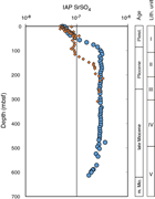
X-ray diffraction (XRD) analyses revealed celestine (SrSO4) between 163 and 393 mbsf, indicating that pore water concentrations of Sr2+ and SO42– attain supersaturation with respect to this mineral (Figure F30). This phenomenon was noted at numerous other DSDP and ODP sites and is related to the increase in Sr2+ as a result of the conversion of biogenic calcite and aragonite to LMC (Baker, 1986; Baker and Bloomer, 1988; Kramer et al., 2000; Swart et al., 1993; Swart and Burns, 1990; Swart and Guzikowski, 1988). At Site U1467, celestine occurs in an interval of unusually high sedimentation rates (see Biostratigraphy) that led to BSR, carbonate recrystallization, and consequent buildup of Sr2+. Therefore, in spite of the reduction of SO42– in this interval, there was sufficient Sr2+ to produce supersaturation with respect to celestine.
Paleomagnetism
Pass-through superconducting rock magnetometer (SRM) measurements were performed on most archive-half cores at 5, 10, or 15 cm intervals with stepwise alternating field (AF) demagnetization up to 30 or 40 mT. Anisotropy of magnetic susceptibility (AMS) was measured in 72 discrete samples, and 6 discrete samples collected from the working halves were fully demagnetized up to 70 mT. Most of the cores drilled with the APC system (Cores 359-U1467A-1H through 4H, 359-U1467B-1H through 37H, and 359-U1467C-1H through 22H) were oriented with the Icefield MI-5 orientation tool, and declination data were used to interpret paleomagnetic data.
Natural remanent magnetization of sedimentary cores
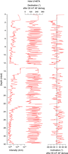
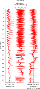
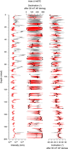
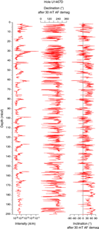
Natural remanent magnetization (NRM) intensity, inclination, and declination in Holes U1467A–U1467D were compared with intensity, inclination, and declination results obtained from demagnetization at 15, 30, and 40 mT. Paleomagnetic directions after demagnetization at 30 mT were used to interpret paleomagnetic data. The two upper units, which consist of unlithified planktonic foraminifer–rich wackestone (lithostratigraphic Units I and II; see Lithostratigraphy), have NRM intensity ranging approximately between 5 × 10⁻⁶ and 1 × 10⁻¹ A/m with the highest intensity found in the upper part of each core and decreasing several orders of magnitude within two to three core sections. The high-intensity peaks were maintained after demagnetization at 30 or 40 mT (Figures F31, F32), indicating that they were not caused by drilling-induced remagnetization but are related to changes in magnetic properties, most likely contamination from drill pipes. As a result, the pipes were cleaned after completing Hole U1467B (see Operations). Although the pipe cleaning reduced the intensity of the drilling-induced magnetization peaks observed in the upper sections, it did not solve the problem entirely. The first two sections of every core continued to show a magnetic overprint. Therefore, we skipped measuring the first two sections of every core after Core 359-U1467C-11H.
The NRM intensity of the lithified planktonic foraminifer–rich wackestone in Unit IV (502.50–707.92 mbsf) deduced from the less contaminated part of the cores (i.e., the bottom sections) ranges approximately from 5 × 10⁻⁶ to 1 × 10⁻⁴ A/m.
Paleomagnetic demagnetization results
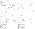
Magnetization by drilling overprint was successfully eliminated at the first step of AF demagnetization (15 mT); however, the directions of characteristic remanent magnetization (ChRM) were seriously flawed because of massive contamination of the sediment cores. Hole U1467A gave no interpretable directions (Figure F31). The upper 190 mbsf of Hole U1467B gave random directions. In the interval between 190 and 255 mbsf, paleomagnetic directions started to behave coherently, possibly because of decreased contamination and a higher NRM, which increased from approximately 1 × 10⁻⁵ to 1 × 10⁻⁴ A/m (Figure F32). Two clear reversals were recognized within this interval in Sections 359-U1467B-24H-6 and 26H-6. Below 255 mbsf, inclinations show a steep downward orientation that might be related to remagnetization and formation of greigite associated with celestine, which was recognized between Cores 19H and 50F. Because Hole U1467C was drilled after cleaning the drill pipes (see Operations), we hoped to interpret the paleomagnetic direction. We removed the first two sections of each core, which despite the cleaning effort still showed significant contamination, and computed the mean Fisher direction for each section to increase the signal-to-noise ratio (Figure F33). Hole U1467D cores were not oriented, and paleomagnetic directions had constant positive inclinations that gave no information about geomagnetic polarity changes (Figure F34).
Demagnetization of six discrete samples from lithostratigraphic Units I–III in Hole U1467B did not allow determination of the ChRM because of the weak intensity (Figure F35). The low intensities measured in the discrete samples, which are taken from the central part of the core, compared to the large intensities measured in the half cores suggests that contamination was limited to the external surface of the cores. The intensities of these discrete samples should be measurable by a cryogenic magnetometer, and we plan to perform these measurements as part of the shore-based research.
Magnetostratigraphy
Most APC cores from Holes U1467A–U1467C were oriented, and polarity was identified using magnetic declination in the few intervals that gave interpretable results. Of about 900 m of recovered core, we only recognized a series of magnetozones between ~100 and 200 mbsf in Hole U1467C and between 195 and 255 mbsf in Hole U1467B (Table T14). These series were interpreted as Chrons C2Ar through C3n.3n (Gradstein et al., 2012) based on the relative length of each polarity zone and on the paleontological age model. A summary of polarity reversals found in Holes U1467B and U1467C is shown in Figure F36.
Table T14. Depth and ages of recognized chron boundaries, Hole U1467B. Download table in .csv format.
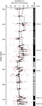
Between 580 and 714 mbsf in Hole U1467C (Cores 24X–37X) the presence of another series of possible normal and reversed polarity intervals is based only on the analysis of inclinations, which are less than 20° and consistent with the paleocolatitude for this site. We tentatively interpret this sequence as Chrons C5n.2n through C5An.2n (Gradstein et al., 2012) (Figure F37).
Physical properties
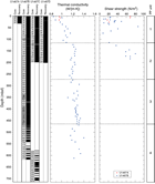
Physical properties were measured on cores from Holes U1467A (0–32 mbsf), U1467B (0–617 mbsf), U1467C (0–714 mbsf), and U1467D (0–201 mbsf). NGR, magnetic susceptibility (on the magnetic susceptibility logger [MSL]), gamma ray attenuation (GRA; bulk density), and P-wave velocity were measured on whole-rounds. Color reflectance and point magnetic susceptibility (MSP) were measured on all archive-half sections. P-wave velocity was also measured on (1) working-half sections with liners from Holes U1467A and U1467B (0–540 mbsf) and (2) discrete paleomagnetic samples without liners from Hole U1467B (540–617 mbsf) and Hole U1467C (580–714 mbsf). Density/porosity measurements were performed on discrete samples, one every other section, on cores from Holes U1467A–U1467C. Thermal conductivity and shear strength measurements were performed on the third section of soft-sediment cores from Holes U1467A and U1467B.
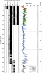
Physical properties, notably P-wave velocity, divide the sedimentary formation into four petrophysical units: Unit 1 from 0 to 115 mbsf, Unit 2 from 115 to 270 mbsf, Unit 3 from 270 to 465 mbsf, and Unit 4 from 465 to 714 mbsf.
Natural gamma radiation
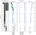
NGR measured on cores from Holes U1467A–U1467D provides insights into sediment lithology and is used for hole-to-hole correlation (see Stratigraphic correlation and sedimentation rates) (Figure F38).
In Unit 1, NGR increases with depth between 0 and 40 mbsf from 0 to about 30 counts/s. From 40 to 115 mbsf, NGR ranges between 20 and 40 counts/s and decreases slightly with depth. Units 2 and 3 display fluctuations and an overall slight decrease. From 115 to 210 mbsf in Unit 2, NGR has the largest range with some high values. A marked decrease in NGR begins at 210 mbsf, reaching about 15 counts/s, but returns to 20 counts/s at 270 mbsf at the boundary to Unit 3. It stays relatively constant at about 20 counts/s to 395 mbsf, where NGR abruptly shifts again about 15 counts/s. This shift coincides with an increase in lithification (see Lithostratigraphy). The sediments recovered in Unit 4 record the transition from darker to lighter successions. This transition is marked by an important increase in NGR to about 45 counts/s at 515 mbsf. From this depth to the bottom of the hole NGR fluctuates between 15 and 40 counts/s.
Density and porosity
Bulk density and porosity also display the four petrophysical units, whereas grain density is constant in all units at about 2.71 g/cm3, which is the density of calcite (Figure F39). In Unit 1, bulk density increases from 1.51 g/cm3 at the seafloor to 1.70 g/cm3 at 50 mbsf and then remains constant to 110 mbsf. Dry density increases from 0.69 to 0.98 g/cm3. Porosity is very high but decreases with depth from 75% to 65% in Unit 1. In Unit 2, bulk density increases with depth between 115 and 170 mbsf but varies from 1.58 to 1.81 g/cm3. Below 170 mbsf, densities are constant at around 1.74 and 1.84 g/cm3 for moisture and density (MAD) and GRA measurements, respectively. Dry density slightly increases with depth from 0.98 to 1.17 g/cm3. Porosities continue to decrease from 65% to 55% to the bottom of this unit and to 52% in Unit 3. Bulk density increases with depth in Unit 3—from 1.72 to 1.82 g/cm3 for MAD measurements and from 1.82 to 1.90 g/cm3 for GRA measurements—and dry density increases from 1.17 to 1.22 g/cm3. In Unit 4, density and porosity display more variability; namely, density continues to increase and porosity decreases, ranging from 2.2 to 1.7 g/cm3 and from 62% to 35%, respectively. Dry density is generally higher than 1.22 g/cm3 and more scattered. In this unit, porosity decreases and density increases coincide with velocity increases and vice versa, reflecting the alternation between cemented and noncemented (soft sediment) layers.
P-wave velocity
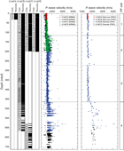
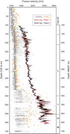
P-wave velocities for all units are shown in Figure F40.
In Unit 1, measurements on whole-round and split cores with the P-wave caliper (PWC) are fairly constant at about 1600 m/s. In Unit 2, whole-round measurements are scattered and reach 2500 m/s and measurements on split cores are similar to those in Unit 1, except for four points with higher velocities, one reaching 2220 m/s. These higher values were measured in intervals with better lithification associated with celestine precipitation (see Lithostratigraphy). The scattered pattern reflects the alternation between lithified and nonlithified intervals. P-wave velocity values in Unit 3 are similar to those in Unit 1.
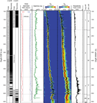
Below 465 mbsf in Unit 4, P-wave velocity increases significantly, locally reaching 4200 m/s because of the abrupt increase in lithification. Likewise, the scattering velocities reflect variations in lithification from hard layers to soft-sediment layers that have velocities close to 2000 m/s. Low velocities close to 1450 m/s in whole-round measurements are related to water or air bubbles in the liner and do not represent rock velocity. P-wave velocity was measured with the logging tool display slightly higher values and a downhole increase in velocity (see Downhole measurements). In addition, a velocity inversion is seen at the bottom of the hole at ~600 mbsf (Figure F47).
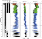
Color reflectance
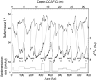
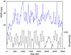
Color reflectance data for all units are shown in Figure F41. Between 0 and 90 mbsf in Unit 1, L* and b* increase slightly from about 40 to 50 and 7 to 10, respectively. They then shift to lower values and reach about 30 and 6, respectively, at the bottom of the unit. a* slightly increases throughout Units 1 and 2. In Unit 2, L*, a*, and b* first have high-frequency variations and are generally constant at 30, 0.7, and 6, respectively, but at 235 mbsf, they increase to 50, 1, and 7, respectively, before decreasing slightly with depth. L* values in Unit 3 are arranged into three cycles of increasing and decreasing values. The lower values in these cycles are around 40 at 280, 340, and 400 mbsf. The higher values are around 55 at 310, 360, and 450 mbsf. These three cycles could be related to eccentricity cycles, particularly L* (see Stratigraphic correlation and sedimentation rates). In Unit 4, the ranges of values increase. L* decreases with depth between 465 and 615 mbsf and then increases with depth between 615 and 714 mbsf. a* values increase with depth from 465 to 550 mbsf and then slightly decrease with depth. b* displays no particular trend with depth.
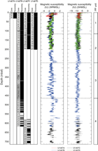
Magnetic susceptibility
In general, magnetic susceptibility is very low and related to the diamagnetic component of high carbonate content sediments of the measured cores (Figure F42). A low offset of magnetic susceptibility values appears between two data sets: measurements with the MSL ranges from about –2 to 0 IU, whereas MSP measurements range from about –10 to –5 IU. For both data sets, constant trends with depth occur. The magnetic susceptibility data suggest that the upper half of every core was contaminated with rust from the drill string (see Paleomagnetism). This magnetic overprint was manually removed from the data presented here.
Thermal conductivity
A total of 69 samples from Holes U1467A and U1467B were measured (Figure F43). Thermal conductivity ranges from 0.853 to 1.399 W/(m·K) with a mean value of 1.202 W/(m·K) (standard deviation = 0.105 W/[m·K]) (Table T15). Thermal conductivity generally increases with depth with the most pronounced increase from 0.853 to 1.252 W/(m·K) between 0 and 70 mbsf in Unit 1. Thermal conductivity decreases slightly in Unit 2 from 1.252 to 1.169 W/(m·K). In Units 3 and 4, thermal conductivity is constant although more variable with depth at about 1.250 W/(m·K).
Table T15. Thermal conductivity, Site U1467. Download table in .csv format.
Shear strength
A total of 28 shear strength measurements were performed in soft sediment with the manual Torvane shear device from 0 to about 185 mbsf (Figure F43). Shear strength does not display any trend with depth.
Discussion
In each petrophysical unit, different diagenetic processes affect the recorded physical properties. In Unit 1, sediments are soft and have high water content. As expected, porosity is high and velocity and density are low. In Units 2 and 3, partial lithification is common, resulting in local increases in P-wave velocity and variability in density and porosity. In Unit 4, the high variability of P-wave velocity, density, and porosity reflects the alternation between cemented and noncemented (soft sediment) layers.
Uranium is the dominant contributor to NGR in Site U1467 sediments (see Downhole measurements) and most commonly reflects the relative abundance of clay and/or organic material within the sediments. Recovered sediments have little to no clay (see Lithostratigraphy) and therefore the major carrier for uranium is organic material (see Geochemistry). The cyclic nature in NGR at Site U1467 may be related to climate cycles (see Stratigraphic correlation and sedimentation rates). Production is tied to the sea level cycle in which sea level highstands flood the bank tops and offbank transported sediment dominates sedimentation in the drift. Confirmation of this process lies in the fact that NGR variations are correlated with the L* record. In each unit, color reflectance L*, a*, and b* display large variations synchronous with the visible dark and light alternating colors of sediments. These repetitive color variations are likely related to cyclic variations in sediment input. The dark levels are possibly related to organic matter preserved during decreased periods of bottom water oxygenation, whereas the light levels are possibly related to more aragonite content (see Lithostratigraphy). These cyclic variations are also used for stratigraphic correlation between different sites (see Stratigraphic correlation and sedimentation rates). Moreover, NGR appears to correlate to eccentricity cycles from 0 to about 465 mbsf.
Downhole measurements
Logging operations
Two holes were logged at this site. Hole U1467C was cored with the APC/XCB system over the course of 3 days. Although the borehole was stable, it was enlarged through most of its depth as a result of rotation and circulation during the multiday coring process. Hole U1467E was drilled for logging with a tricone bit over a shorter time period and consequently was in good condition for downhole logging.
Hole U1467C
Downhole logging measurements were made in Hole U1467C after completion of XCB coring to a total depth of 714 m drilling depth below seafloor (DSF) at 1050 h on 3 November 2015. In preparation for logging, the hole was swept with 30 bbl of high-viscosity mud and the drill pipe was raised to 102 m DSF. Because the borehole had been stable throughout the coring process, no logging mud was used; logging was carried out with seawater as the logging fluid. During rig-up of the first downhole logging tool string, there was backflow from the pipe. A slug of heavy mud was pumped to dampen the flow. Seas were calm throughout logging operations, and the wireline heave compensator was not used. The triple combo was the only tool string deployed in Hole U1467C.
The full triple combo tool string, measuring gamma ray, porosity, density, electrical resistivity, and magnetic susceptibility, was rigged up and run into the borehole at 1806 h on 3 November (Figure F44). A downlog was started in the pipe just above the seafloor and continued to total depth at 1212 m wireline depth below rig floor (WRF; 713 m wireline depth below seafloor [WSF]). A short uplog pass was made at the bottom of the hole to show repeatability of tool measurements. The tool string was run back to total depth, and the main pass was recorded from the bottom of the hole to the seafloor at 365 m/h. The caliper that estimates borehole diameter was open to its maximum extent (~17 inches) through most of the hole, with the exception of a short interval from 350 to 465 m wireline matched depth below seafloor (WMSF). As a result of the enlarged borehole size and associated potential negative effects on data quality for measurements made with the FMS-sonic and VSI tool strings, it was decided to end logging operations in Hole U1467C after the triple combo run and carry out the planned downhole logging in a dedicated hole.
Hole U1467E
Hole U1467E was drilled to 714 m DSF with a 9⅞ inch tricone bit on 5 November 2015. In preparation for logging, a 30 bbl high-viscosity mud sweep was circulated, the bit was dropped to the bottom of the hole, and the pipe was pulled to 99 m DSF. The logging fluid was seawater, as conditions had been good during drilling. The sea state was calm throughout logging operations with average heave <0.3 m peak-to-peak. Three tool strings were deployed in Hole U1467E: the triple combo, the VSI, and the FMS-sonic (Figure F44).
At 0010 h on 6 November, the triple combo tool string descended from the rig floor into the borehole. A downlog proceeded at 610 m/h from just above the seafloor in pipe and reached the base of the hole at 1212 m WRF (714 m WSF). A short uplog was run from 1212 to 1085 m WRF (714 to 587 m WSF) to provide data to crosscheck with the main pass. The tool string was run back to total depth, and the main pass was run from the bottom of the hole to seafloor at a speed of 365 m/h.
The caliper log from the first logging run indicated that much of the borehole was ~14 inches in diameter, thus suitable for a VSP experiment. The VSI tool string was the second deployment in Hole U1467E because it must be run during daylight hours. Marine mammal watch began at ~0600 h, and the air gun ramp-up began 1 h later. The parallel cluster of air guns was positioned at ~3 m below the sea surface for the VSP, as the subseafloor targets were relatively shallow, and the hydrophone was suspended 2 m below the cluster. Only one 250 in3 air gun was used for the VSP in Hole U1467E because the target depths were shallow and to more closely replicate the source used during preexpedition seismic surveys (Betzler et al., 2013; Lüdman et al., 2013). The VSI tool string was lowered into the hole at 0622 h. Before reaching the bottom of the hole, a short uplog was taken to depth-match distinctive features in the VSI gamma ray log with the other logging runs. The tool string tagged the bottom of the hole at 1189 m WRF (691 m WSF), indicating that >20 m of fill had accumulated in the bottom of the hole since the first logging run. The VSP experiment began at 0808 h, and good sonic waveforms were recorded at 13 stations in the open-hole interval. Stations were spaced at roughly 50 m intervals. The survey was finished at 1040 h, and the tool string was returned to the rig floor and rigged down.
Rig up of the third tool string, the FMS-sonic, was completed at 1320 h, and a downlog was taken at 550 m/h from just above the seafloor in pipe to a total depth of 1180 m WRF (682 m WSF). Standard (high-) frequency Dipole Shear Sonic Imager (DSI) transmitter settings were used for the monopole (for compressional wave measurement) and upper dipole (for shear wave measurement), and low-frequency settings were used for the lower dipole (for shear wave measurement). Two upward passes with the FMS-sonic tool string were run, Pass 1 to the base of the drill pipe and Pass 2 to the seafloor, at a speed of 365 m/h. The tool string was brought up to the rig floor and rigged down. Logging operations at Site U1467 were completed by 1950 h on 6 November.
Downhole log data quality
During shore-based processing, all logging curves for each hole were depth-matched using the total gamma ray log from the main pass of the triple combo tool string as a reference log and shifted to a seafloor depth reference, allowing a unified depth scale to be produced (WMSF). Features in gamma ray logs from each logging pass were aligned to the reference log to produce a complete depth-matched data set. The data were shifted to the WMSF scale based on the depth of the step increase in gamma ray that indicated the seafloor during the downlog, measured at 499.5 m WRF in Hole U1467C and 498.2 m WRF in Hole U1467E.
The quality of the Hole U1467C logging data is compromised by the enlarged borehole diameter (Figure F45). The caliper on the triple combo tool string was open to its maximum extent (approximately 17 inches) for much of the logged interval. Gamma ray and resistivity logs are generally reasonable even in larger diameter boreholes, whereas density and porosity measurements require that the logging tools have good contact with the borehole wall. The gamma ray log from Hole U1467C correlates well with NGR measurements on cores. The density log correlates with MAD measurements on cores from Holes U1467B and U1467C between 290 and 610 m WMSF, but there is a reduction in density log values above and below this interval, suggesting that the borehole may be severely washed out. The porosity log shows anomalously high values throughout the hole compared to MAD porosity data and is not a reliable indicator of formation porosity in this hole. The magnetic susceptibility log shows relatively consistent values in the upper 430 m of the hole, but below this depth the susceptibility log shifts to lower values.
The quality of downhole logging data from Hole U1467E is good, with the borehole diameter ranging from 11 to 17 inches (Figure F46). Several larger diameter intervals below ~540 m WMSF are at the same depths where core recovery was particularly low in Holes U1467B and U1467C. The gamma ray, density, and porosity logs correlate well with measurements on cores throughout the logged interval, even in the deeper section of the borehole. Resistivity and sonic velocity logs are generally robust to the moderate changes in borehole diameter in Hole U1467E (Figures F46, F47). The DSI recorded P&S monopole, Stoneley, and lower and upper dipole modes in Hole U1467E. The resulting slowness data were converted to acoustic velocities: compressional wave velocity (VP) from the monopole and shear velocity (VS) from the upper and lower dipoles. High coherence in sonic waveforms is indicated by orange to red areas in the compressional and shear velocity tracks in Figure F47. These data indicate the DSI was successful in capturing compressional and shear arrivals through the logged interval. A comparison of compressional wave velocity between the two passes of the FMS-sonic tool string shows excellent agreement between the two passes (Figure F48), providing further evidence that the data quality is good. FMS resistivity images were also of good quality, with pads making contact with the borehole walls through most of the open-hole interval.
During a VSP, typically 5–20 shots are recorded at each station; ideally, 5 shots are stacked in order to minimize the signal-to-noise ratio and provide the best waveforms for picking first arrival times. In Hole U1467E, a relatively small number of shots (93) were needed to pick clear arrivals at 13 stations. At 9 of the 13 stations, at least 5 clean shots were recorded for stacking. The high-quality seismic data from the VSP was likely due to several factors, including the excellent weather conditions (no significant heave), the positioning of the air guns at 3 m below sea surface (rather than deeper at 5–7 m), and the use of a single air gun to avoid excess power and possible synchronization noise.
Comparison of log data quality, Holes U1467C and U1467E
Log data in Holes U1467C and U1467E cover a significant overlapping interval between 100 and 680 mbsf that permits an assessment of log data quality, particularly in wide boreholes (Figure F49). Hole U1467C was cored with the APC/XCB system with an 11⁷⁄₁₆ inch bit, whereas Hole U1467E was a dedicated logging hole drilled with a 9⅞ inch tricone bit. In addition to the smaller bit size used in Hole U1467E, the drilling time (approximately 24 h) was much shorter. Hole U1467C was cored and drilled alternately over several days, with significant water circulation while coring.
Caliper data from the triple combo tool string show that most of Hole U1467C was wider than the maximum extent of the caliper arm (~17 inches), whereas much of Hole U1467E was much closer to bit size (Figure F49). It is interesting to note that the caliper logs show small washed-out intervals at approximately 10 m spacing. These features were observed in Hole U1467C in the interval where the caliper made contact with the borehole wall (~350–465 m WMSF) and in Hole U1467E, which was drilled without coring. Part of hole preparation for logging included rotating and pumping for several hours with the pipe at a fixed depth to clean out the hole. Shipboard evaluation of cored material from Site U1467 indicates that the formation could be washed away fairly easily with any mechanical contact or wear. Based on the spacing of these features, they may correspond to the location of joints in the BHA, which are slightly larger in diameter than the rest of the pipe.
Gamma ray logs have the same features in both holes, though the values are slightly lower in the wider borehole. Correction for hole diameter based on the caliper log is part of data processing for the gamma ray measurement. However, in holes like Hole U1467C, where the caliper arm was extended to its maximum reach, the correction was made by assuming a 17 inch diameter, which should be considered the minimum diameter in those intervals. It is not possible to accurately correct for borehole sizes greater than the ~17 inch caliper limit.
Density and porosity logs provide clear evidence of the differences between the two holes. The density logs show close correspondence in the interval where the caliper made contact with the borehole wall in Hole U1467C. There is also reasonable overlay in the interval below ~490 m WMSF, where the caliper in Hole U1467C was at its maximum extent, suggesting the borehole may have been close to the 17 inch limit. It can be assumed that the widest sections of Hole U1467C correspond to the intervals where the density log values drop dramatically to as low as 1.25 g/cm3. In these intervals, measurements are likely dominated by the density of the borehole fluid (seawater, with a typical density of ~1.03 g/cm3) rather than the density of the formation. Based on the comparison of logging data from Holes U1467C and U1467E, porosity logs are the most highly affected by the wider diameter of the borehole. The Hole U1467C porosity log presents values between 10% and 40% higher than the porosity values from MAD measurements in the same hole.
Electrical resistivity is measured by the High-Resolution Laterolog Array (HRLA) at five different depths of investigation in the borehole. The deepest measurement (R5) is least affected by variations in borehole diameter, and “true resistivity” (RT) is calculated from all five depths of investigation. In general, the RT logs from both holes overlay very well. Separation between holes is distinct in the interval between ~610 and 650 m WMSF, where most of the other logs also show anomalous values likely due to the enlarged borehole. The RT log apparently overcorrects in this interval, providing higher resistivity values in Hole U1467C than in Hole U1467E.
The magnetic susceptibility logs show the same features in both holes, with nearly identical character and amplitude. In the wider borehole, the susceptibility log shows an offset to lower values that increase with depth. The implication of the comparison of these two logs is that although relative changes in magnetic susceptibility are likely accurate, the absolute values measured by the magnetic susceptibility tool are less reliable in wider boreholes.
Logging units
The logged intervals at Site U1467 were divided into four units based on distinct changes in character and trends in gamma ray, resistivity, and sonic velocity data (Figures F45, F46, F47, F50). Logging Unit 4 was divided into two subunits on the basis of small-scale changes in gamma ray, density, resistivity, and compressional wave velocity logs.
Logging Unit 1 (base of drill pipe to 212 m WMSF)
Logging Unit 1 is characterized by moderate- to high-amplitude variability in total gamma ray, density, resistivity, and sonic velocity logs. Gamma ray decreases slightly from ~40 American Petroleum Institute gamma radiation units (gAPI) at the top of the unit to 31 gAPI at 139 m WMSF, where a step increase is observed, and then decreases to the base of the unit. Similar to Site U1466 (see Downhole measurements in the Site U1466 chapter [Betzler et al., 2017c]), spectral data from Site U1467 indicate that uranium is the primary contributor to variability in total gamma ray (Figure F50). Density and resistivity logs show subtle increases with depth; VP increases with depth from ~1650 m/s at the top of the unit to 2000 m/s at the base.
Logging Unit 2 (212–501 m WMSF)
The logging Unit 1/2 boundary is marked by a steep decrease in the total gamma ray log and a change to moderate- to low-amplitude variability in the gamma ray and resistivity logs (Figure F46). This logging unit has the lowest mean gamma ray value (24 gAPI) of the entire logged interval. There is a distinctive high-amplitude, longer wavelength feature in gamma ray (377–394 m WMSF); deeper in the unit, there is evidence of longer wavelength cycles in gamma ray data, on the order of 10–20 m in thickness, to the base of the unit at 501 m WMSF. Both VP and VS values increase with depth through logging Units 1 and 2 with no clear change in the velocity trend between units. At the base of logging Unit 2, VP approaches 2300 m/s. An increase in coherence in the velocity data associated with the transition into logging Unit 2 may be due to the relatively consistent borehole diameter through this unit.
Logging Unit 3 (501–606 m WMSF)
Logging Unit 3 is characterized by a change to moderate- to high-amplitude variability in all logging measurements. Gamma ray values are higher than in logging Unit 2, with a mean value of 38 gAPI. Logging Unit 3 is distinguished by the highest density (mean = 1.9 g/cm3) and resistivity (mean = 2.09 Ωm) values measured in the entire logged interval at Site U1467. Density and resistivity logs show similar features, with high-density features corresponding to high resistivity values. Sonic logs show a change to higher velocity values (VP range = 2300–3000 m/s) and higher amplitude variability in this unit. Discrete multimeter-scale intervals of increasing and decreasing sonic velocity correspond to the same trends in density and resistivity. Lower coherence appears in the sonic waveforms, particularly in the monopole (VP) and upper dipole (VS) data.
Logging Unit 4 (606–714 m WMSF)
The logging Unit 3/4 boundary is based on a distinct change in the character of nearly all logged measurements. Gamma ray, density, resistivity, and velocity decrease below the unit boundary, and the amplitude of variability in the density, resistivity, and sonic logs drops in logging Unit 4. The unit is divided into Subunits 4A and 4B, but it is difficult to interpret whether this distinction is meaningful because of the limited depth interval with full data coverage.
Logging Subunit 4A (606–650 m WMSF) is characterized by a change in amplitude of variability, from higher to lower, in all logged properties. There is a general decreasing then increasing trend in gamma ray, density, resistivity, and sonic velocity values within the subunit. A feature with locally elevated gamma ray, density, resistivity, and velocity values centered at 628 m WMSF marks the change in trend from increasing to decreasing values.
Logging Subunit 4B (650–714 m WMSF) is distinguished from Subunit 4A by two main criteria. First, there is a subtle change from low- to moderate-amplitude variability in the gamma ray, density, and resistivity logs across the subunit boundary. Second, there is a return to the trend of more consistent increasing sonic velocities with depth that characterizes logging Units 1 and 2.
Formation MicroScanner images
In Hole U1467E, FMS electrical resistivity images were acquired between 110 and 660 m WMSF. The quality of FMS image data depends on close contact between the measuring pads on the tool and the borehole wall. The FMS borehole images recorded in Hole U1467E are of good quality as a result of the long intervals with borehole diameter less than 14 inches (as measured by the FMS calipers; Figure F47) and the calm sea state. Good quality FMS data allows the borehole formation resistivity in Hole U1467E to be interpreted at multiple scales.
At the scale of the borehole, the interval shallower than ~201 m WMSF (logging Unit 1) is characterized by alternating layers of relatively high conductivity (dark color in FMS images) and moderate resistivity (Figure F51A). The moderate resistivity (light color in FMS images) layers generally range from 10 to 100 cm in thickness, separated by thicker (meter-scale) intervals of high conductivity. This unit correlates to lithostratigraphic Unit II, which consists of interlayered unlithified and partially lithified layers.
Deeper than 212 m WMSF (within logging Unit 2), FMS images reveal a change from alternating high conductivity and moderate resistivity to generally high conductivity between ~295 and 330 m WMSF (Figure F51B). This interval of background of high conductivity has a speckled texture with centimeter-scale, high-resistivity features that may be celestine fragments and nodules observed in cores through this interval (see Lithostratigraphy and Geochemistry). Based on its depth, this interval may be correlated with Drift Sequence (DS) DS5 (see Seismic stratigraphy). Below this interval, the character of FMS images returns to alternating high conductivity and moderate resistivity layers, followed by a general increase in resistivity to 501 m WMSF (Figure F51C). In dynamic FMS images, this interval has a mottled character that likely reflects bioturbation in the sediments where more conductive, organic-rich material fills burrows (lithostratigraphic Unit IV; see Lithostratigraphy).
Logging Unit 3 is characterized by the appearance of high-resistivity layers, tens of centimeters in thickness, alternating with moderately resistive intervals. High-resistivity layers increase in frequency through the base of the unit at 606 m WMSF, and transitions between layers are sharp. High-resistivity intervals generally correlate with higher values in the density and resistivity logs and lower values in the gamma ray logs (for example, 540–560 m WMSF) (Figure F52). Core recovery through this interval is poor, but based on sediments recovered higher in the section, high-resistivity layers are likely correlated with fine-grained, white wackestone layers in lithostratigraphic Unit V (see Lithostratigraphy).
Below 606 m WMSF, FMS images reveal a change to more moderate conductivities and the appearance of high-resistivity layers decreases dramatically (Figure F51D). Logging Unit 4 corresponds to lithostratigraphic Unit VI, as reflected in a sharp change in images and petrophysical properties. This unit is also bioturbated, and FMS images show a mottled texture similar to that of logging Unit 2, above. Boundaries between layers remain sharp, but there is less contrast in the resistivity properties of these layers compared to those in the overlying logging unit.
Vertical seismic profile and sonic velocity
Data provided by the VSP and sonic velocity logs in Hole U1467E help establish the conversion between depth and two-way traveltime (TWT) and link the borehole data (both from cores and downhole logs) to the seismic section.
Good stacks of sonic waveforms were recorded during the VSP experiment. All 13 stations yielded good check shot traveltimes, ranging from 0.8360 s TWT at 155.5 m WMSF to 1.3167 s TWT at the deepest station at 682.9 m WMSF (Figure F44; Table T16). Measured traveltimes were picked based on the first break of the sonic waveform and were corrected to the sea level datum.
Table T16. VSP experiment direct arrival times, Site U1467. Download table in .csv format.
Sonic traveltimes were also calculated from sonic log velocities and give two-way traveltimes very close to those from the VSP (Figure F53). Sonic velocity logs were recorded in Hole U1467E between 141 and 660 m WMSF, and velocities generally increase downhole to 606 m WMSF. There are multiple distinct velocity inversions in the sonic logs between 500 m WMSF and the base of the logged interval, the most prominent of which occurs at the top of logging Subunit 4A (Figure F47). This also coincides with the lithology change into lithostratigraphic Unit VI, a white lithified wackestone to packstone unit (see Lithostratigraphy). The compressional wave velocities from downhole logging differ significantly from physical properties measurements on cores, both discrete sample and whole-round measurements (Figure F50; see Physical properties). Core-based velocities suggest a relatively constant mean value with depth between ~60 and 405 m core depth below seafloor (CSF-A) with some higher point values. In contrast, logged velocities range from 1700 to 3000 m/s from 98 m WMSF to total depth, generally increasing with depth to the velocity inversion at 606 m WMSF. There is a 500 m/s offset between the two data sets at 405 m WMSF. The general change in character deeper than 405 m WMSF is reflected in the cores and logs, but there is a significant offset between the two data sets. The offset may reflect a number of factors, including destruction of the primary formation fabric during drilling and the difference in vertical resolution of the measurements. However, the difference in data sets may also be a result of the challenges of measuring velocity on shipboard samples: inadequate contact between transducers and core material, void space where core liners are not completely full (which may vary with coring method rather than core recovery rate), microcracks/fractures/voids that are not detectable in split half cores, and sampling bias. Discrepancies between shipboard and downhole velocity measurements have been observed during other scientific ocean drilling expeditions in a variety of drilling environments (e.g., ODP Leg 166: Shipboard Scientific Party, 1997; IODP Expedition 341: Jaeger et al., 2014).
The measured VSP and integrated sonic log traveltime values can also be compared with the seismic velocity model from expedition site survey data (Figure F53). To calculate traveltime from the sonic logs, a velocity of 1.615 km/s was assumed from seafloor to the top of the logged interval, based on the mean P-wave velocity measured on discrete core samples from Hole U1467B, and the deepest velocity measurement by the sonic log (1.6 km/s at 660 m WMSF) was used to extrapolate to the base of the hole. Interval velocities from the VSP in Hole U1467E are faster than measured velocities from downhole logs, which themselves are faster than velocities predicted by the preexpedition seismic velocity model. The time-depth curve for Site U1467 based on the VSP is shifted to lower traveltimes compared to the preexpedition model. At the deepest VSP station depth (682.9 m WSF), there is a difference of ~2% between traveltimes from the VSP and those predicted by the extrapolated sonic log and a difference of ~13% between the VSP and the preexpedition model. For more discussion, see Seismic stratigraphy.
Downhole temperature
Downhole temperature measurements were planned for Hole U1467A, but problems with the APC system led to the hole being abandoned after only four cores (see Operations). Four temperature measurements were made using the APCT-3 between 22.5 and 79.5 mbsf in Hole U1467B (Table T17).
Table T17. APCT-3 temperature measurements, Site U1467. Download table in .csv format.
All measurements were made in good sea state (<1 m swell). The APCT-3 was stopped at the mudline for at least 5 min prior to each penetration. The average mudline temperature was difficult to determine in several of the deployments but appeared to range between 13.8° and 15°C (Table T17). Unlike previous Expedition 359 deployments, no evidence of frictional heating occurred during the four attempted penetrations of the APCT-3 in Hole U1467B. The temperature series data show what appears to be postpenetration decay after the time of assumed penetration, and all deployments show evidence of frictional heating when the probe is assumed to be pulled from the formation. Standpipe pressure data, when synchronized with the temperature time series, indicate that the APC system was firing consistently at expected pressures during these APCT-3 deployments. However, as a result of the uncertainty in these temperature data, none of the equilibrium temperatures are considered fully reliable.
Mudline temperatures are higher than temperatures measured in sediment at Site U1467, and a linear temperature gradient with depth cannot be assumed. Geothermal gradient and heat flow could not be determined from the four unreliable measurements at this site.
Stratigraphic correlation and sedimentation rates
Determining the relative position of core gaps among the various holes at Site U1467 during drilling was accomplished using gamma ray attenuation (GRA) data collected at 5 cm resolution on the Whole-Round Multisensor Logger (WRMSL). Although at lower resolution and delayed relative to drilling, NGR provided another evaluator for sedimentary completeness among the four holes cored at Site U1467. Total depths of Holes U1467B (617.2 mbsf) and U1467C (714 mbsf) allowed NGR measurements to be completed for the upper ~200 mbsf in both holes and evaluated prior to drilling of Hole U1467D. Particular attention was placed on the interval in Core 359-U1467B-11H, which was recovered with shattered core liner and disturbed sediment. Hole U1467C spanned much of this interval, but unknown gaps remained between Cores 10H and 11H and Cores 11H and 12H. Hole U1467D was started at 1.5 mbsf (by drilling down) to fill in core gaps in Hole U1467C.
Correlations were accomplished using IODP Correlator software (version 2.0.1). High-resolution compositing (decimeter scale; see Stratigraphic correlation and sedimentation rates in the Expedition 359 methods chapter [Betzler et al., 2017a]) was based on reflectance L* from the Section Half Imaging Logger (SHIL) at 2.5 cm resolution for the first four cores in Holes U1467A–U1467D (~35 mbsf) and down to the tenth core in Holes U1467B–U1467D (~90 mbsf).
NGR was used for compositing Cores 359-U1467B-13H through 18H, 359-U1467C-11H through 18H, and 359-U1467D-11H through 18H (~90–160 mbsf) because GRA and L* variations were unclear among the holes in this interval. However, distinct “highs” in GRA appeared in the lowermost cores (Cores 359-U1467B-19H, 359-U1467C-19H, and 359-U1467D-18H) and provided correlation points for the bottom portion of the splice. For detailed description of the GRA, NGR, and L* data sets, see Physical properties in the Expedition 359 methods chapter (Betzler et al., 2017a).
The composite depth scale and splice at Site U1467 are constructed from 0.0 to 220.25 m core composite depth below seafloor (CCSF-D) (“mudline” in Hole U1467C to the bottom of Core 359-U1467B-22H) (Figure F54). Below the splice, Hole U1467B and U1467C cores (with unknown gaps in each) are appended with a constant affine value (Tables T18, T19). Uncertainty in moving between cores within the splice (CCSF-D) based on *L and GRA tie points is estimated to be 10 cm but may be as high as 30 cm for some ties. Uncertainty in tie points in the splice based on NGR may be on the order of 30 to 50 cm.
Table T18. Splice tie points, Site U1467. Download table in .csv format.
Table T19. Splice intervals, Site U1467. Download table in .csv format.
The growth rate is 7% for the composited sections in Holes U1467B–U1467D (0–204.81 mbsf) (Table T19). Composited growth rates on many paleoceanography expeditions are on the order of 15%. The lower growth rate at Site U1467 reflects low clay content in the cores, good weather with calm sea state, and low tidal range (~0.5 m), producing a composited section close to the drilled depth.
Age model and sedimentation rates
An age model was established for Site U1467 on the basis of all available biostratigraphic and paleomagnetic age control points. For details, see Biostratigraphy, Paleomagnetism, and Lithostratigraphy. The uppermost ~130 mbsf has an average sedimentation rate of 3.4 cm/ky (Figure F55). The spliced L* record from 0 to 32 m CCSF-D was compared with the stacked benthic δ18O record (Lisiecki and Raymo, 2005), showing a good correlation to the 0 to 800 ky interval. Based on this comparison, sedimentation rate averaged 4 cm/ky on the CCSF-D scale and scales to 3.74 cm/ky on the mbsf scale (1.07 growth factor), which is in good agreement with the biostratigraphic estimate. Assuming that L* is a proxy for marine isotope stages, interglacial sedimentation rates approached 10 cm/ky versus glacial rates of 2 to 4 cm/ky (Table T20). If confirmed by shore-based stable isotope analyses, this result is consistent with other carbonate platforms (e.g., Betzler et al., 2013; Eberli, Swart, Malone, et al., 1997; Isern, Anselmetti, Blum, et al., 2002): increased production of aragonite on bank tops during Late Pleistocene sea level highstands dictates sedimentation rate variability and controls relative proportion of aragonite to other sedimentary components (reflected by L*).
Table T20. Tie points, Site U1467. Download table in .csv format.
The upper 140 m CCSF-D of the spliced NGR record was compared to the Laskar et al. (2004) orbital solution over the last 3.5 My, showing common traits with eccentricity (Figure F56). NGR was tied to the 405 ky eccentricity cycle assuming the minima correlate, producing independent age estimates for upper Pliocene to Pleistocene sections at Site U1467. The resulting average sedimentation rate is 4.2 cm/ky (relative to CCSF-D), which scales to 3.9 cm/ky (relative to mbsf), again similar to the biostratigraphic age model. Sedimentation rates among the long eccentricity packets range between 3.2 and 5.0 cm/ky.
Seismic stratigraphy
Site U1467 is located in the Inner Sea northwest of North Male atoll in a water depth of 487 m, approximately 9 km south of ODP Site 716. The site is located in a distal position in relation to the platform margins and moats. The nearly horizontally layered seismic reflections of the drift sequences at Site U1467 show no truncations and no indications of mass wasting from the adjacent platform margin (Figure F57). Thus, it provided a complete undisturbed succession of all drift sequences (DS1–DS9) mapped by Lüdmann et al. (2013) and the youngest platform sequences (PS; PS9–PS11) (Betzler et al., 2013). It is the main paleoceanographic site of the expedition and comprises a continuous record from the middle Miocene to the present. In addition, the accurate time-depth conversion placed the age-depth model provided by biostratigraphy into the seismic sections and thus determined the ages of the sequence boundaries within the drift succession.
Time-depth conversion
To make the most accurate P-wave velocity model for time-depth conversion, a dedicated logging hole, U1467E, was drilled. Downhole logging was successfully completed including the check shot survey with 12 stations (see Downhole measurements). The waveforms of the recorded shots were of high quality with a high signal-to-noise ratio, and consequently, first arrival times were easy to pick. Figure F58 shows the resulting interval velocities and the downhole DSI sonic velocities. The sonic velocities are slightly lower and mimic the trend of the VSP data (Figure F51). The previous velocity model deviates from the measured velocities, which were higher than expected. The velocity in the oldest drift sequences (DS1–DS3) reaches 2600–3000 m/s with a concurrent increase in density, resistivity, and gamma ray (bulk density [RHOM], computed true resistivity [RT_HRLT], and total spectral gamma ray [HSRG]; Figure F58). Figure F59 shows the time-depth conversion for Site U1467, and Table T21 provides the numerical tabulation of the time-depth conversion.
Table T21. DS boundaries, Site U1467. Download table in .csv format.
Seismic facies and geometries
At Site U1466, the seismic facies of the drift sequences are generally characterized by alternation of low to medium amplitudes that are replaced in the lower part of Site U1467 (1240 ms TWT) by bundles of strong reflections separated by zones of weak echoes comprising DS1–DS3 (Figure F57). The base of the drift succession lies at 1337 ms TWT and is underlain by the distal bottomsets of PS9–PS11. Here in the basin, all sequence boundaries appear as continuous parallel high-amplitude reflections and are the correlative conformities to the unconformities along the basin margin that define the sequence boundaries.
The thickness of the drift sequences varies from 24.5 m (DS7) to 104 m (DS6) with a maximum of 172.5 m (DS4). The basinal drift succession carries the record of the bottom-current system and its major reorganization in the Inner Sea Basin (Lüdmann et al., 2013). Initially, the Inner Sea was a semi-enclosed basin connected with the open ocean via the proto-Kardiva Channel, allowing a restricted water mass exchange probably going back to the deposition of PS7. During this time, the Inner Sea had an empty bucket geometry that was rapidly filled while the entire platform slowly subsided, resulting in a relatively constant water depth of approximately 500 m at Site U1467. Starting with DS1–DS3, the depocenter was situated at the western basin margin dominated by a southward bottom water inflow from the northeast Kardiva Channel and inflow from the newly opened northwest Kardiva Channel (Lüdmann et al., 2013). Accordingly, the sedimentation rate at the basinal site was low and sequence thicknesses were small. DS4–DS7 mark the gradual shift of the locus of deposition from the western to the eastern platform margin. This shift is accompanied by the onset of a northward bottom-current flow within the Inner Sea along its eastern margin (Lüdmann et al., 2013). This event began with the deposition of DS5. The uppermost sequences (DS8–DS9) exhibit more uniform thicknesses throughout the Inner Sea, with a local depocenter near the exits of passages between the atolls where current speed slows down.
Core-seismic correlation
With the exception of DS3, which coincides with the base of Unit V, drift sequence boundaries in the basin do not correlate well with lithostratigraphic units (Figure F58). The correlation of DS3 with the base of Unit V might be explained by the fact that drift boundaries predominantly represent reorganization of the current regime and to a lesser extent significant changes in lithology, with materials reaching basinal Site U1467 tending to be uniform for long periods of time. Fluctuations in current intensity may have occurred during the deposition of each drift sequence, reflected by changes in grain size and density. Similar features are displayed in DS4 (see RHOM log, Figure F58). Variations in gamma ray are primarily related to the uranium content that reaches its maximum concentration in DS3. DS2 is characterized by a significant decrease in all physical properties, including NGR, resistivity, density, and sonic velocity (see Downhole measurements).
Time-depth conversion places the base of lithostratigraphic Unit I, unlithified foraminifer-rich wackestone to mudstone, in the middle of DS8 at 109.74 mbsf (Section 359-U1467B-14H-1) (Figure F58). Lithostratigraphic Unit II, an interval of interlayered, unlithified, and partially lithified wackestone, terminates in the upper part of DS6 at 215.5 mbsf. The underlying lithostratigraphic Unit III, partially lithified wackestone to packstone, terminates at 309.4 mbsf (Section 359-U1467B-34H-CC) very close to the boundary of DS6, placed at 295.5 mbsf. Although the lithostratigraphic Unit IV/V boundary is marked by significant changes in gamma ray, density, and velocity, it is not a seismic sequence boundary (Figure F58). The DS3 boundary at 603 mbsf coincides with the top of lithostratigraphic Unit VI at 602 mbsf. This boundary reflects a significant change from predominantly gray to light greenish sediment to white lithified fine-grained planktonic foraminifer–rich wackestone that is representative of the earliest drift sequences (DS1 and DS2). These deposits represent the basinal equivalent of the thick white prograding drift that onlaps the western platform margin (Figure F57). Marginal Sites U1466 and U1468 are in a high-speed current regime, and consequently the finer fraction is winnowed out during the deposition of DS1 and DS2 and transported basinward. Lithostratigraphic Units V and VI are composed of alternations of soft and competent layers, which results in high impedance contrasts that in turn result in high-amplitude reflections in DS1–DS3. The base of the drift does not contain age-diagnostic microfossils, but the absence of the LO of F. fohsi indicates an age younger than 13.41 Ma (see Biostratigraphy).
References
Aiello, G., Barra, D., and Parisi, R., 2015. Lower–Middle Pleistocene ostracod assemblages from the Montalbano Jonico section (Basilicata, Southern Italy). Quaternary International, 383:47–73. http://dx.doi.org/10.1016/j.quaint.2014.11.010
Alvarez Zarikian, C.A., 2015. Cenozoic bathyal and abyssal ostracods beneath the South Pacific Gyre (IODP Expedition 329 Sites U1367, U1368 and U1370). Palaeogeography, Palaeoclimatology, Palaeoecology, 419:115–142. http://dx.doi.org/10.1016/j.palaeo.2014.07.024
Alvarez Zarikian, C.A., Stepanova, A.Y., and Grützner, J., 2009. Glacial–interglacial variability in deep sea ostracod assemblage composition at IODP Site U1314 in the subpolar North Atlantic. Marine Geology, 258(1–4):69–87. http://dx.doi.org/10.1016/j.margeo.2008.11.009
Backman, J., Raffi, I., Rio, D., Fornaciari, E., and Pälike, H., 2012. Biozonation and biochronology of Miocene through Pleistocene calcareous nannofossils from low and middle latitudes. Newsletters on Stratigraphy, 45(3):221–244. http://dx.doi.org/10.1127/0078-0421/2012/0022
Baker, P.A., 1986. Pore-water chemistry of carbonate-rich sediments, Lord Howe Rise, Southwest Pacific Ocean. In Kennett, J.P., von der Borch, C.C., et al., Initial Reports of the Deep Sea Drilling Project, 90: Washington, DC (U.S. Government Printing Office), 1249–1256. http://dx.doi.org/10.2973/dsdp.proc.90.132.1986
Baker, P.A., and Bloomer, S.H., 1988. The origin of celestite in deep-sea carbonate sediments. Geochimica et Cosmochimica Acta, 52(2):335–339. http://dx.doi.org/10.1016/0016-7037(88)90088-9
Betzler, C., Eberli, G.P., Alvarez Zarikian, C.A., Alonso-García, M., Bialik, O.M., Blättler, C.L., Guo, J.A., Haffen, S., Horozal, S., Inoue, M., Jovane, L., Kroon, D., Lanci, L., Laya, J.C., Ling Hui Mee, A., Lüdmann, T., Nakakuni, M., Nath, B.N., Niino, K., Petruny, L.M., Pratiwi, S.D., Reijmer, J., Reolid, J., Slagle, A.L., Sloss, C.R., Su, X., Swart, P.K., Wright, J.D., Yao, Z., and Young, J.R., 2017a. Expedition 359 methods. In Betzler, C., Eberli, G.P., Alvarez Zarikian, C.A., and the Expedition 359 Scientists, Maldives Monsoon and Sea Level. Proceedings of the International Ocean Discovery Program, 359: College Station, TX (International Ocean Discovery Program). http://dx.doi.org/10.14379/iodp.proc.359.102.2017
Betzler, C., Eberli, G.P., Alvarez Zarikian, C.A., Alonso-García, M., Bialik, O.M., Blättler, C.L., Guo, J.A., Haffen, S., Horozal, S., Inoue, M., Jovane, L., Kroon, D., Lanci, L., Laya, J.C., Ling Hui Mee, A., Lüdmann, T., Nakakuni, M., Nath, B.N., Niino, K., Petruny, L.M., Pratiwi, S.D., Reijmer, J., Reolid, J., Slagle, A.L., Sloss, C.R., Su, X., Swart, P.K., Wright, J.D., Yao, Z., and Young, J.R., 2017b. Expedition 359 summary. In Betzler, C., Eberli, G.P., Alvarez Zarikian, C.A., and the Expedition 359 Scientists, Maldives Monsoon and Sea Level. Proceedings of the International Ocean Discovery Program, 359: College Station, TX (International Ocean Discovery Program). http://dx.doi.org/10.14379/iodp.proc.359.101.2017
Betzler, C., Eberli, G.P., Alvarez Zarikian, C.A., Alonso-García, M., Bialik, O.M., Blättler, C.L., Guo, J.A., Haffen, S., Horozal, S., Inoue, M., Jovane, L., Kroon, D., Lanci, L., Laya, J.C., Ling Hui Mee, A., Lüdmann, T., Nakakuni, M., Nath, B.N., Niino, K., Petruny, L.M., Pratiwi, S.D., Reijmer, J., Reolid, J., Slagle, A.L., Sloss, C.R., Su, X., Swart, P.K., Wright, J.D., Yao, Z., and Young, J.R., 2017c. Site U1466. In Betzler, C., Eberli, G.P., Alvarez Zarikian, C.A., and the Expedition 359 Scientists, Maldives Monsoon and Sea Level. Proceedings of the International Ocean Discovery Program, 359: College Station, TX (International Ocean Discovery Program). http://dx.doi.org/10.14379/iodp.proc.359.104.2017
Betzler, C., Fürstenau, J., Lüdmann, T., Hübscher, C., Lindhorst, S., Paul, A., Reijmer, J.J.G., and Droxler, A.W., 2013. Sea-level and ocean-current control on carbonate-platform growth, Maldives, Indian Ocean. Basin Research, 25(2):172–196. http://dx.doi.org/10.1111/j.1365-2117.2012.00554.x
Betzler, C., Lüdmann, T., Hübscher, C., and Fürstenau, J., 2013. Current and sea-level signals in periplatform ooze (Neogene, Maldives, Indian Ocean). Sedimentary Geology, 290:126–137. http://dx.doi.org/10.1016/j.sedgeo.2013.03.011
Boersma, A., 1990. Late Oligocene to late Pliocene benthic foraminifers from depth traverses in the central Indian Ocean. In Duncan, R.A., Backman, J., Peterson, L.C., et al., Proceedings of the Ocean Drilling Program, Scientific Results, 115: College Station, TX (Ocean Drilling Program), 315–379. http://dx.doi.org/10.2973/odp.proc.sr.115.146.1990
Boersma, A., and Mikkelsen, N., 1990. Miocene-age primary productivity episodes and oxygen minima in the central equatorial Indian Ocean. In Duncan, R.A., Backman, J., Peterson, L.C., et al., Proceedings of the Ocean Drilling Program, Scientific Results, 115: College Station, TX (Ocean Drilling Program), 589–609. http://dx.doi.org/10.2973/odp.proc.sr.115.162.1990
Coles, G.P., Whatley, R.C., and Moguilevsky, A., 1994. The ostracod genus Krithe from the Tertiary and Quaternary of the North Atlantic. Palaeontology, 37(1):71–120.
Douglas, R., and Heitman, H., 1979. Slope and basin benthic foraminifera of the California Borderland. In Doyle, L., and Pilkey, O. (Eds.), Geology of the Continental Slopes. Special Publication - Society of Economic Paleontologists and Mineralogists, 27:231–246. http://archives.datapages.com/data/sepm_sp/SP27/Slope_and_Basin_Benthic.pdf
Eberli, G.P., Swart, P.K., Malone, M.J., et al., 1997. Proceedings of the Ocean Drilling Program, Initial Reports, 166: College Station, TX (Ocean Drilling Program). http://dx.doi.org/10.2973/odp.proc.ir.166.1997
Fisher, R.A., 1953. Dispersion on a sphere. Proceedings of the Royal Society of London, Series A, 217:295–305.
Gieskes, J.M., 1983. The chemistry of interstitial waters of deep sea sediments: interpretation of deep sea drilling data. In Riley, J.P., and Chester, R. (Eds.), Chemical Oceanography (Volume 8): London (Academic), 221–269.
Gradstein, F.M., Ogg, J.G., Schmitz, M.D., and Ogg, G.M. (Eds.), 2012. The Geological Time Scale 2012: Amsterdam (Elsevier).
Hilgen, F.J., Lourens, L.J., and Van Dam, J.A., 2012. The Neogene period. With contributions by A.G. Beu, A.F. Boyes, R.A. Cooper, W. Krijgsman, J.G. Ogg, W.E. Piller, and D.S. Wilson. In Gradstein, F.M., Ogg, J.G., Schmitz, M.D., and Ogg, G.M. (Eds.), The Geologic Time Scale: Oxford, United Kingdom (Elsevier), 923–978. http://dx.doi.org/10.1016/B978-0-444-59425-9.00029-9
Imbrie, J., Hays, J.D., Martinson, D.G., McIntyre, A., Mix, A.C., Morley, J.J., Pisias, N.G., Prell, W.L., and Shackleton, N.J., 1984. The orbital theory of Pleistocene climate: support from a revised chronology of the marine δ18O record. In Berger, A., Imbrie, J., Hays, J., Kukla, G., and Saltzman, B. (Eds.), Milankovitch and Climate (Part 1): Hingman, MA (D. Riedel Publishing Company), 269–305.
Isern, A.R., Anselmetti, F.S., Blum, P., et al., 2002. Proceedings of the Ocean Drilling Program, Initial Reports, 194: College Station, TX (Ocean Drilling Program). http://dx.doi.org/10.2973/odp.proc.ir.194.2002
Jaeger, J.M., Gulick, S.P.S., LeVay, L.J., Asahi, H., Bahlburg, H., Belanger, C.L., Berbel, G.B.B., Childress, L.B., Cowan, E.A., Drab, L., Forwick, M., Fukumura, A., Ge, S., Gupta, S.M., Kioka, A., Konno, S., März, C.E., Matsuzaki, K.M., McClymont, E.L., Mix, A.C., Moy, C.M., Müller, J., Nakamura, A., Ojima, T., Ridgway, K.D., Rodrigues Ribeiro, F., Romero, O.E., Slagle, A.L., Stoner, J.S., St-Onge, G., Suto, I., Walczak, M.H., and Worthington, L.L., 2014. Site U1421. In Jaeger, J.M., Gulick, S.P.S., LeVay, L.J., and the Expedition 341 Scientists, Proceedings of the Integrated Ocean Drilling Program, 341: College Station, TX (Ocean Drilling Program). http://dx.doi.org/10.2204/iodp.proc.341.107.2014
Kirschvink, J.L., 1980. The least-squares line and plane and the analysis of palaeomagnetic data. Geophysical Journal of the Royal Astronomical Society, 62(3):699–718. http://dx.doi.org/10.1111/j.1365-246X.1980.tb02601.x
Klinkhammer, G.P., and Palmer, M.R., 1991. Uranium in the oceans: where it goes and why. Geochim et Cosmochimica Acta, 55(7):1799–1806. http://dx.doi.org/10.1016/0016-7037(91)90024-Y
Kramer, P.A., Swart, P.K., De Carlo, E.H., and Schovsbo, N.H., 2000. Overview of interstitial fluid and sediment geochemistry, Sites 1003–1007 (Bahamas transect). In Swart, P.K., Eberli, G.P., Malone, M.J., and Sarg, J.F. (Eds.), Proceedings of the Ocean Drilling Program, Scientific Results, 166: College Station, TX (Ocean Drilling Program), 179–195. http://dx.doi.org/10.2973/odp.proc.sr.166.117.2000
Laskar, J., Robutel, P., Joutel, F., Gastineau, M., Correia, A.C.M., and Levrard, B., 2004. A long-term numerical solution for the insolation quantities of the Earth. Astronomy & Astrophysics, 428(1):261–285. http://dx.doi.org/10.1051/0004-6361:20041335
Lisiecki, L.E., and Raymo, M.E., 2005. A Pliocene–Pleistocene stack of 57 globally distributed benthic δ18O records. Paleoceanography, 20(1):PA1003. http://dx.doi.org/10.1029/2004PA001071
Lourens, L., Hilgen, F., Shackleton, N.J., Laskar, J., and Wilson, D., 2004. The Neogene period. In Gradstein, F.M., Ogg, J.G., and Smith, A. (Eds.), A Geologic Time Scale 2004: Cambridge, United Kingdom (Cambridge University Press), 409–440. http://dx.doi.org/10.1017/CBO9780511536045.022
Lüdmann, T., Kalvelage, C., Betzler, C., Fürstenau, J., and Hübscher, C., 2013. The Maldives, a giant isolated carbonate platform dominated by bottom currents. Marine and Petroleum Geology, 43:326–340. http://dx.doi.org/10.1016/j.marpetgeo.2013.01.004
Majoran, S., and Agrenius, S., 1995. Preliminary observations on living Krithe praetexta praetexta (Sars, 1866), Sarsicytheridea bradii (Norman, 1865) and other marine ostracods in aquaria. Journal of Micropaleontology, 14(2):96. http://dx.doi.org/10.1144/jm.14.2.96
McDuff, R.E., 1985. The chemistry of interstitial waters, Deep Sea Drilling Project Leg 86. In Heath, G.R., Burckle, L.H., et al., Initial Reports of the Deep Sea Drilling Project, 86: Washington, DC (U.S. Government Printing Office), 675–687. http://dx.doi.org/10.2973/dsdp.proc.86.131.1985
Poag, C.W., and Low, D., 1985. Environmental trends among Neogene benthic foraminifers at Deep Sea Drilling Project Site 548, Irish continental margin. In de Graciansky, P.C., Poag, C.W., et al., Initial Reports of the Deep Sea Drilling Project, 80: Washington, DC (U.S. Government Printing Office), 489–503. http://dx.doi.org/10.2973/dsdp.proc.80.112.1985
Raffi, I., Backman, J., Fornaciari, E., Pälike, H., Rio, D., Lourens, L., and Hilgen, F., 2006. A review of calcareous nannofossil astrobiochronology encompassing the past 25 million years. Quaternary Science Reviews, 25(23–24):3113–3137. http://dx.doi.org/10.1016/j.quascirev.2006.07.007
Reardon, E.J., and Armstrong, D.K., 1987. Celestite (SrSO4(s)) solubility in water, seawater and NaCl solution. Geochimica et Cosmochimica Acta, 51(1):63–72. http://dx.doi.org/10.1016/0016-7037(87)90007-X
Rio, D., Fornaciari, E., and Raffi, I., 1990. Late Oligocene through early Pleistocene calcareous nannofossils from western equatorial Indian Ocean (Leg 115). In Duncan, R.A., Backman, J., Peterson, L.C., et al., Proceedings of the Ocean Drilling Program, Scientific Results, 115: College Station, TX (Ocean Drilling Program), 175–235. http://dx.doi.org/10.2973/odp.proc.sr.115.152.1990
Schlager, W., Reijmer, J., and Droxler, A.W., 1994. Highstand shedding of carbonate platforms. Journal of Sedimentary Research, B64:270–281.
Schrag, D.P., Hampt, G., and Murray, D.W., 1996. Pore fluid constraints on the temperature and oxygen isotopic composition of the glacial ocean. Science, 272(5270):1930–1932. http://dx.doi.org/10.1126/science.272.5270.1930
Shipboard Scientific Party, 1988. Introduction. In Backman, J., Duncan, R.A., et al., Proceedings of the Ocean Drilling Program, Initial Reports, 115: College Station, TX (Ocean Drilling Program), 5–15. http://dx.doi.org/10.2973/odp.proc.ir.115.102.1988
Shipboard Scientific Party, 1997. Site 1006. In Eberli, G.P., Swart, P.K., Malone, M.J., et al., Proceedings of the Ocean Drilling Program, Initial Reports, 166: College Station, TX (Ocean Drilling Program), 233–287. http://dx.doi.org/10.2973/odp.proc.ir.166.109.1997
Swart, P.K., and Burns, S.J., 1990. Pore-water chemistry and carbonate diagenesis in sediments from Leg 115: Indian Ocean. In Duncan, R.A., Backman, J., Peterson, L.C., et al., Proceedings of the Ocean Drilling Program, Scientific Results, 115: College Station, TX (Ocean Drilling Program), 629–645. http://dx.doi.org/10.2973/odp.proc.sr.115.187.1990
Swart, P.K., and Guzikowski, M., 1988. Interstitial-water chemistry and diagenesis of periplatform sediments from the Bahamas, ODP Leg 101. In Austin, J.A., Jr., Schlager, W., et al., Proceedings of the Ocean Drilling Program, Scientific Results, 101: College Station, TX (Ocean Drilling Program), 363–380. http://dx.doi.org/10.2973/odp.proc.sr.101.158.1988
Swart, P.K., Isern, A., Elderfield, H., and McKenzie, J.A., 1993. A summary of interstitial-water geochemistry of Leg 133. In McKenzie, J.A., Davies, P.J., Palmer-Julson, A., et al., Proceedings of the Ocean Drilling Program, Scientific Results, 133: College Station, TX (Ocean Drilling Program), 705–721. http://dx.doi.org/10.2973/odp.proc.sr.133.258.1993
Thompson, P.R., Bé, A.W.H., Duplessy, J.-C., and Shackleton, N.J., 1979. Disappearance of pink-pigmented Globigerinoides ruber at 120,000 yr BP in the Indian and Pacific Oceans. Nature, 280(5723):554–558. http://dx.doi.org/10.1038/280554a0
Wade, B.S., Pearson, P.N., Berggren, W.A., and Pälike, H., 2011. Review and revision of Cenozoic tropical planktonic foraminiferal biostratigraphy and calibration to the geomagnetic polarity and astronomical time scale. Earth-Science Reviews, 104(1–3):111–142. http://dx.doi.org/10.1016/j.earscirev.2010.09.003
Young, J.R., 1990. Size variation of Neogene Reticulofenestra coccoliths from Indian Ocean DSDP cores. Journal of Micropaleontology, 9:71–85. http://dx.doi.org/10.1144/jm.9.1.71
Young, J.R., 1998. Neogene. In Bown, P.R. (Ed.), Calcareous Nannofossil Biostratigraphy: Dordrecht, The Netherlands (Kluwer Academic Publishing), 225–265.
Young, J.R., Pratiwi, S., Su, X., and the Expedition 359 Scientists, 2017. Data report: surface seawater plankton sampling for coccolithophores undertaken during IODP Expedition 359. In Betzler, C., Eberli, G.P., Alvarez Zarikian, C.A., and the Expedition 359 Scientists, Maldives Monsoon and Sea Level. Proceedings of the International Ocean Discovery Program, 359: College Station, TX (International Ocean Discovery Program). http://dx.doi.org/10.14379/iodp.proc.359.111.2017
Zijderveld, J.D.A., 1967. AC demagnetization of rocks: analysis of results. In Collinson, D.W., Creer, K.M., and Runcorn, S.K. (Eds.), Methods in Palaeomagnetism: Amsterdam (Elsevier), 254–286.
1 Betzler, C., Eberli, G.P., Alvarez Zarikian, C.A., Alonso-García, M., Bialik, O.M., Blättler, C.L., Guo, J.A., Haffen, S., Horozal, S., Inoue, M., Jovane, L., Kroon, D., Lanci, L., Laya, J.C., Ling Hui Mee, A., Lüdmann, T., Nakakuni, M., Nath, B.N., Niino, K., Petruny, L.M., Pratiwi, S.D., Reijmer, J.J.G., Reolid, J., Slagle, A.L., Sloss, C.R., Su, X., Swart, P.K., Wright, J.D., Yao, Z., and Young, J.R., 2017. Site U1467. In Betzler, C., Eberli, G.P., Alvarez Zarikian, C.A., and the Expedition 359 Scientists, Maldives Monsoon and Sea Level. Proceedings of the International Ocean Discovery Program, 359: College Station, TX (International Ocean Discovery Program). http://dx.doi.org/10.14379/iodp.proc.359.105.2017
2 Expedition 359 Scientists’ addresses.
This work is distributed under the Creative Commons Attribution 4.0 International (CC BY 4.0) license. 
- F1. Location map of Site U1467.
- F2. Seismic section, Site U1467.
- F3. Lithostratigraphic summary, Site U1467.
- F4. Sieved sample showing preservation of components, Site U1467.
- F5. Celestine, Site U1467.
- F6. Fine fraction, Site U1467.
- F7. Main color changes in cores, Site U1467.
- F8. Range of thickness, average thickness, and percentage of core occupied by lighter intervals in Units V and VI.
- F9. Lighter and darker intervals and associated color reflectance and NGR data.
- F10. Light reflectance and NGR data across the Unit V/VI boundary, Hole U1467C.
- F11. Planktonic foraminifer-rich wackestone with abundant planktonic foraminifers and rare benthic foraminifers.
- F12. Biostratigraphic and paleoenvironmental summary, Site U1467.
- F13. Age-depth profile, Site U1467.
- F14. Enlarged age-depth profile for the Pliocene and Pleistocene, Site U1467.
- F15. Small Reticulofenestra event, Hole U1467B.
- F16. Plate of selected planktonic foraminifers, Site U1467.
- F17. Plate of Pleistocene large agglutinated benthic foraminifers, Site U1467.
- F18. Plate of representative benthic foraminifers, Site U1467.
- F19. Plate of middle to late Miocene bolivinid benthic foraminifers, Site U1467.
- F20. Plate of radiolarians from mudline sample, Hole U1467B.
- F21. IW Cl–, Na+, and K+ concentrations, Holes U1467A–U1467C.
- F22. IW alkalinity, hydrogen (pH), and SO42– concentrations, Holes U1467A–U1467C.
- F23. IW Ca2+, Mg2+, Sr2+, and Li+ concentrations, Holes U1467A–U1467C.
- F24. IW Sr2+/Ca2+, Mg2+/Ca2+, Ca2+/Cl–, and Mg2+/Cl–, Holes U1467A–U1467C.
- F25. IW Fe, B, Ba, and Si concentrations, Holes U1467A–U1467C.
- F26. Carbonate and organic carbon contents, Holes U1467A–U1467C.
- F27. Relative concentrations of aragonite, HMC, LMC, dolomite, and quartz measured using XRD, Site U1467.
- F28. Sr/Ca, Mg/Ca, Mn/Ca, and Fe/Ca, ratios of sediments, Site U1467.
- F29. Methane and ethane concentrations in headspace, Site U1467.
- F30. Ion activity product (IAP) of SrSO4, Site U1467.
- F31. NRM intensity, declination, and inclination, Hole U1467A.
- F32. NRM intensity, declination, and inclination, Cores 359-U1467B-1H through 37H.
- F33. NRM intensity, declination, and inclination, Hole U1467C.
- F34. NRM intensity, declination, and inclination, Hole U1467D.
- F35. Representative vector endpoint diagrams of magnetization directions, Site U1467.
- F36. NRM intensity, declination, and inclination with magnetostratigraphy, Holes U1467B and U1467C.
- F37. Inclination and magnetostratigraphy, Cores 359-U1467B-24X through 37X.
- F38. NGR, Site U1467.
- F39. Bulk density from GRA and MAD, grain and dry density, and porosity, Site U1467.
- F40. P-wave velocity from the WRMSL, split cores, and discrete samples, Site U1467.
- F41. Color reflectance, Site U1467.
- F42. Magnetic susceptibility, Site U1467.
- F43. Thermal conductivity and shear strength, Site U1467.
- F44. Logging operations, Site U1467.
- F45. Triple combo logs, Hole U1467C.
- F46. Triple combo logs, Hole U1467E.
- F47. Downhole logs recorded by Pass 2 of the FMS-sonic tool string, Hole U1467E.
- F48. P-wave velocity from the sonic velocity log in Hole U1467E and cores from Holes U1467B and U1467C.
- F49. Downhole logs, Holes U1467C and U1467E.
- F50. NGR logs, Hole U1467E.
- F51. FMS images, Hole U1467E.
- F52. FMS images illustrating high-resistivity layering in logging Unit 3, Hole U1467E.
- F53. Time-depth curves and P-wave velocity, Site U1467.
- F54. Spliced L*, NGR, and GRA records, Site U1467.
- F55. Spliced L* record, Site U1467.
- F56. Spliced NGR record, Site U1467.
- F57. Seismic section of drift sequences, Site U1467.
- F58. Correlation of seismic, log, and core data, Site U1467.
- F59. Time-depth conversion, Site U1467.
- T1. Site U1467 core summary.
- T2. Biostratigraphic events, Site U1467.
- T3. Nannofossil range chart, Holes U1467A, U1467B, and U1467C.
- T4. Planktonic foraminifer range chart, Hole U1467A.
- T5. Planktonic foraminifer range chart, Hole U1467B.
- T6. Planktonic foraminifer range chart, Hole U1467C.
- T7. Benthic foraminifer range chart, Holes U1467A, U1467B, and U1467C.
- T8. Ostracod range chart, Holes U1467A U1467B, and U1467C.
- T9. Interstitial water chemistry, Site U1467.
- T10. Carbon and nitrogen, Site U1467.
- T11. XRD results, Site U1467.
- T12. Solids geochemistry, Site U1467.
- T13. Headspace hydrocarbons, Site U1467.
- T14. Depth and ages of recognized chron boundaries, Hole U1467B.
- T15. Thermal conductivity, Site U1467.
- T16. VSP experiment direct arrival times, Site U1467.
- T17. APCT-3 temperature measurements, Site U1467.
- T18. Splice tie points, Site U1467.
- T19. Splice intervals, Site U1467.
- T20. Tie points, Site U1467.
- T21. DS boundaries, Site U1467.

