Sun, Z., Jian, Z., Stock, J.M., Larsen, H.C., Klaus, A., Alvarez Zarikian, C.A., and the Expedition 367/368 Scientists
Proceedings of the International Ocean Discovery Program Volume 367/368
publications.iodp.org
https://doi.org/10.14379/iodp.proc.367368.109.2018

Site U15051
Zhimin Jian, Hans Christian Larsen, Carlos A. Alvarez Zarikian, Zhen Sun, Joann M. Stock, Adam Klaus, Jacopo Boaga, Stephen A. Bowden, Anne Briais, Yifeng Chen, Deniz Cukur, Kelsie A. Dadd, Weiwei Ding, Michael J. Dorais, Eric C. Ferré, Fabricio Ferreira, Akira Furusawa, Aaron J. Gewecke, Jessica L. Hinojosa, Tobias W. Höfig, Kan-Hsi Hsiung, Baoqi Huang, Enqing Huang, Xiao-Long Huang, Shijun Jiang, Haiyan Jin, Benjamin G. Johnson, Robert M. Kurzawski, Chao Lei, Baohua Li, Li Li, Yanping Li, Jian Lin, Chang Liu, Chuanlian Liu, Zhifei Liu, Antonio Luna, Claudia Lupi, Anders J. McCarthy, Geoffroy Mohn, Lachit Singh Ningthoujam, Michael Nirrengarten, Nobuaki Osono, David W. Peate, Patricia Persaud, Ning Qiu, Caroline M. Robinson, Sara Satolli, Isabel Sauermilch, Julie C. Schindlbeck, Steven M. Skinner, Susanne M. Straub, Xiang Su, Liyan Tian, Froukje M. van der Zwan, Shiming Wan, Huaichun Wu, Rong Xiang, Rajeev Yadav, Liang Yi, Cuimei Zhang, Jinchang Zhang, Yang Zhang, Ning Zhao, Guangfa Zhong, and Lifeng Zhong2
Keywords: International Ocean Discovery Program, IODP, JOIDES Resolution, Expedition 367, Expedition 368, Site U1505, northern South China Sea, continent–ocean transition zone, outer margin high, hyperextension, continental breakup, thinning, rifting, T60 unconformity, Oligocene, high sedimentation rate, greigite
MS 367368-109: Published 28 September 2018
Site summary
Background and objectives
Site U1505 (proposed Site SCSII-3D; Sun et al., 2016) is located at 2916.6 m water depth on a broad regional basement high (Figure F1). This site was an alternate to Site U1501, should time be left for drilling following completion of the high-priority sites included in the Scientific Prospectus (Sun et al., 2016). Site U1505 was included in Expedition 368 because it might complement findings at Site U1501 and it was within the operational limits of 3400 m drill string imposed by the failure of the drawworks.
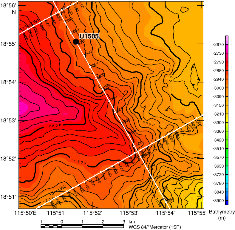
Figure F1. Bathymetry with seismic lines.
Both Sites U1505 and U1501 are located on the same structural high at similar water depths and are 10.5 km apart (Figure F2). The seismic section at Site U1505 generally shows a more horizontal orientation of the seismic reflectors and concordant relationship of the strata than the one at Site U1501, indicating the sediment sequence at Site U1505 should be more complete. The key objective at Site U1505 was to sample the stratigraphic record above seismic unconformity T80 (inferred before drilling to be ~38 Ma in age), and specific goals were to constrain both (1) the sediment responses to the tectonic events and basin evolution since the Eocene and (2) Neogene paleoceanographic and paleoclimatological changes along the northern South China Sea (SCS) margin.
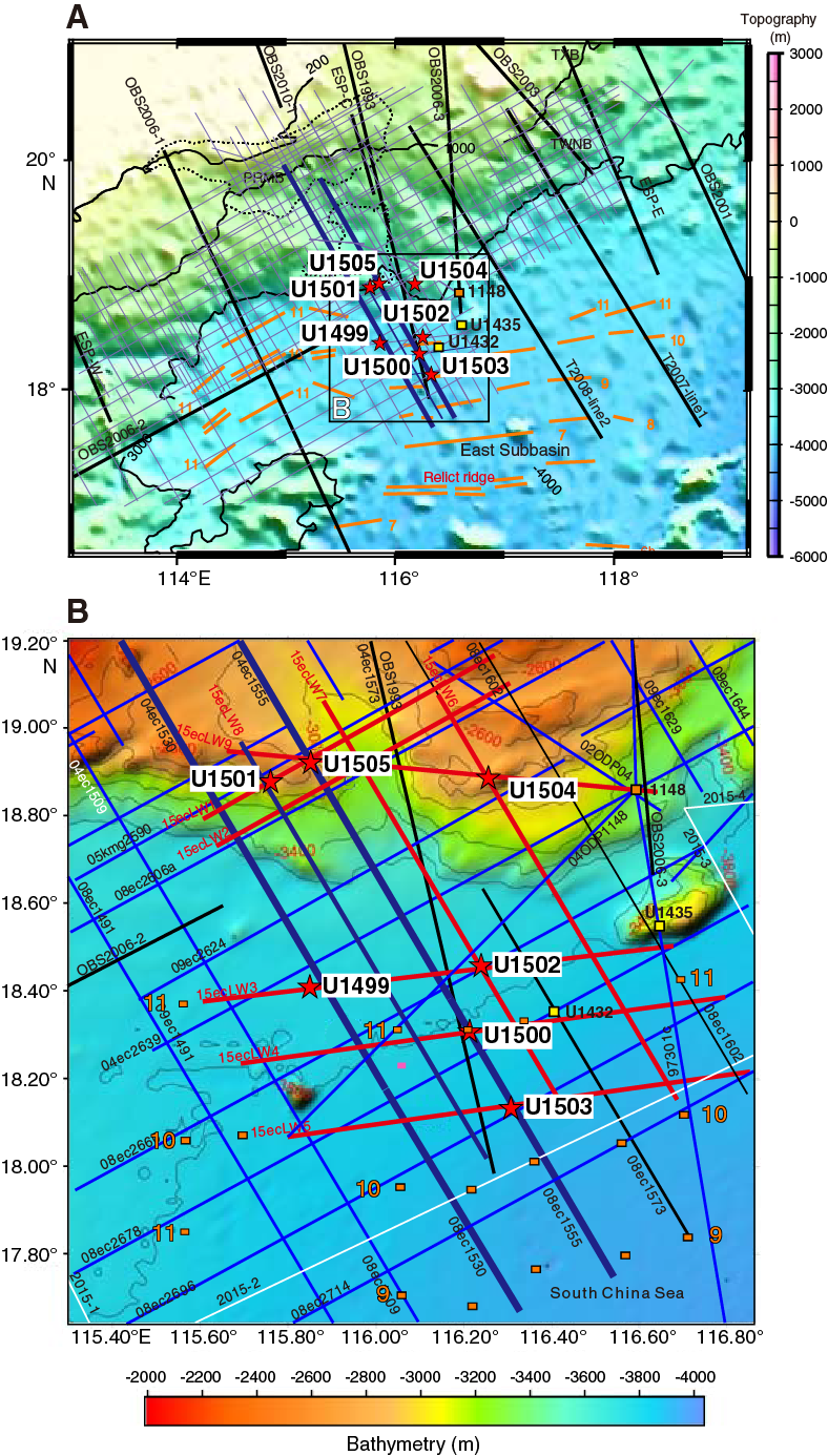
Figure F2. Northern SCS margin with seismic coverage.
The relatively shallow 2916.6 m water depth at Site U1505 makes it one of the few Ocean Drilling Program (ODP)/Integrated Ocean Drilling Program/International Ocean Discovery Program (IODP) sites above the modern carbonate compensation depth (CCD) of the SCS. The site’s hemipelagic deposits, rich in calcareous microfossils, enable the application of stable isotopes, faunal analyses, and other multidisciplinary methods. Key objectives were to reconstruct the east Asian monsoonal climate record in the SCS and upper- and deep-water variations in the western Pacific. Site U1505 will, for the first time, provide an almost continuous sequence of paleoceanographic studies at orbital and millennial timescales since the late Eocene in the SCS. We cored two holes at this site with the advanced piston corer (APC) system to obtain a continuous record of the Pliocene–Pleistocene interval for high-resolution paleoceanographic studies.
Operations
Four holes were cored with the APC and extended core barrel (XCB) systems at Site U1505. In Hole U1505A (18°55.0560′N, 115°51.5369′E; 2916.6 m water depth), Core 1H misfired and recovered only 0.3 m. In Hole U1505B (18°55.0562′N, 115°51.5370′E; 2918.6 m water depth), a 3.23 m long mudline core was recovered for future education and outreach activities. Hole U1505C (18°55.0570′N, 115°51.5370′E; 2917.4 m water depth) was cored with the APC system to 317 m and then cored with the XCB system to 480.2 m, recovering 480.15 m (100%). Hole U1505D (18°55.0485′N, 115°51.5501′E; 2917.5 m water depth) was cored with the APC system to 184.5 m and recovered 191.43 m (104%). Downhole logging with a modified triple combination (triple combo) tool string was conducted in Hole U1505C from 341.2 m uphole. The maximum drilling depth of 480.2 m was determined by the possible maximum total length (3400 m) of drill string deployment.
Lithostratigraphy
The sediment succession recovered at Site U1505 extends from the Oligocene to the Pleistocene. Two sedimentary units (I and II) were observed (Figure F3). Lithostratigraphic Unit I is dominated by nannofossil ooze with varying amounts of foraminifers and clay, as well as biogenic silica in the upper interval of the hole. Unit I is divided into three subunits (IA–IC). Subunit IA (Hole U1505C = 0.00–27.76 m) is composed of dark greenish gray and greenish gray biosiliceous-rich clay with nannofossils, nannofossil-rich clay with biogenic silica, and nannofossil-rich biosiliceous ooze with clay. The abundance of biogenic silica decreases downhole. A pinkish gray, ~6 cm thick, slightly fining upward ash layer occurs at 20.8 m (Hole U1505C), and ash pods were observed at 20.3 m in Hole U1505D. Subunit IB (Hole U1505C = 27.76–273.39 m) is composed of gray to brown nannofossil ooze with minor silty intervals. The color change reflects the varying abundance of foraminifers and clay. Subunit IC (Hole U1505C = 273.39–403.79 m) is composed of gray, greenish gray, and light brownish gray clay-rich nannofossil ooze (with foraminifers) and foraminifer-rich nannofossil ooze with clay and minor amounts of nannofossil-rich clay. Unit II (Hole U1505C = 403.50–480.54 m) is dominated by dark greenish gray, well-consolidated silty clay and clayey silt (with nannofossils).

Figure F3. Lithostratigraphic and biostratigraphic summary.
Biostratigraphy
All core catcher samples from Holes U1505A–U1505C were analyzed for calcareous nannofossils, planktonic foraminifers, and diatoms. Additional samples were taken from intervals within the working-half sections when necessary to refine the ages. Hole U1505D was not sampled continuously for biostratigraphic analyses because of time constraints at the end of the expedition, but the sequence recovered spans from the late Miocene to the present (Figure F3). Preservation of calcareous microfossils is good in Cores 368-U1505C-1H through 48X and moderate to poor in Cores 49X through 64X. Planktonic foraminifers are abundant or common in Cores 1H through 56X and 59X through 62X and rare in Cores 57X, 58X, 63X, and 64X. Calcareous nannofossils are generally abundant to common in most samples from Hole U1505C, except for those from the upper part of Core 57X.
Forty-five biostratigraphic datums identified in Hole U1505C suggest a continuous succession from the early Oligocene to the Holocene (Figure F3). The Pleistocene/Pliocene boundary is placed within Core 7H, the Pliocene/Miocene boundary is placed between Cores 11H and 13H, and the Miocene/Oligocene boundary is placed between Cores 54X and 55X. Sedimentation rates are ~7 mm/ky in the Oligocene, ~15 mm/ky during the Miocene–Pliocene, and ~24 mm/ky during the Pleistocene.
Relatively low abundances of planktonic foraminifers deeper than Core 57X indicate bathyal depths during the early Oligocene, whereas much higher abundances of planktonic foraminifers shallower than Core 56X suggest a deeper water environment since the late Oligocene.
Paleomagnetism
Only natural remanent magnetization (NRM) was measured with the superconducting rock magnetometer (SRM) in Hole U1505C, except for Sections 1H-1 through 3H-1, which were in-line alternating field (AF) demagnetized in three steps. Most of the 55 AF demagnetized discrete samples show very soft magnetic behavior responsible for the acquisition of a strong, vertical drilling overprint (average inclination = ~81°) that was removed by demagnetization to 10–15 mT. This soft behavior shows that magnetic remanence is dominated by multidomain to pseudosingle-domain titanomagnetite or magnetite. The drilling overprint appears to impact discrete samples far less than core sections (Figure F19). The lower part of the hole (Cores 48X through 64X) is characterized by severe drilling disturbance, which causes a large scatter of NRM directions and inclinations.
Magnetostratigraphic data are based on polarities assigned to the archive-half sections and corroborated by directions obtained from oriented discrete samples. The lower boundary of the Brunhes (C1n) normal chron is at 37.4 m (0.781 Ma). The lower boundary (57.4 m) of the reverse polarity r1 is the base of Subchron C1r.3r with an age of 1.778 Ma.
Geochemistry
Low but measurable hydrocarbon gases were detected only in Cores 368-U1505C-53X through 60X (371–438 m). The base of the hole has methane distributions similar to those at Site U1499, whereas the uppermost section is barren of methane, similar to Site U1501. Except for the shallowest 30 m of sediment, total organic carbon (TOC), total nitrogen (TN), and total sulfur (TS) contents are mostly low in lithostratigraphic Unit I, but TS and TOC are slightly higher in Unit II; however, in all cases they are typically <1 wt% (Figure F4). Interstitial water chemistry has two important features. The upper part of the hole exhibits patterns similar to those at Site U1501; inhibited sulfate reduction and low chlorine, bromine, and salinity suggest the presence of freshwater at depth. Freshwater at >400 m coincides with the presence of low quantities of methane and the T60 regional seismic unconformity.

Figure F4. Chemical anomalies associated with T60.
Physical properties and downhole measurements
Physical property data were acquired from cores from Holes U1505C (0–480.5 m) and U1505D (0–184 m), including density, magnetic susceptibility, P-wave velocity, natural gamma radiation (NGR), color reflectance, and thermal conductivity. Physical property trends allow us to define two physical property units, PP Units 1 (0–403 m) and 2 (403–480 m). The boundary between Units 1 and 2 displays a distinct color change from greenish and light brownish gray to dark greenish gray. This boundary, which corresponds to the seismic stratigraphic T60 unconformity, is associated with a sharp change in physical properties. In Unit 1, sediments in the upper part are composed of foraminifer-rich nannofossil ooze with clay that gradually changes to clay-rich nannofossil ooze in the lower part. This change is well reflected in the NGR, which increases with depth. The higher NGR values in Unit 2 are related to sediment that primarily consists of silty clay. Magnetic susceptibility values overall gradually decrease with depth. The boundary between Units 1 and 2 shows that density and P-wave velocity values drop sharply from ~2.2 to ~1.8 g/cm3 and from ~2250 to 1750 m/s, respectively. Porosity values abruptly increase from ~35% to ~50%. Thermal conductivity also shows a sharp change at the boundary. Reflectance parameters L* and red, green, blue (RGB) data are well correlated with carbonate content.
Wireline logging was conducted in Hole U1505C using the triple combo tool string, which included the Hostile Environment Natural Gamma Ray Sonde (HNGS), Hostile Environment Litho-Density Sonde (HLDS), Dipole Sonic Imager (DSI), and magnetic susceptibility sonde (MSS). This logging string collected good data from 341.2 m (139.1 m above the bottom of Hole U1505C), which allows the definition of six logging units that mostly correlate with the lithostratigraphic units and core physical property data. Logging Unit 1 extends from the seafloor to the base of the drill pipe at 78 m. NGR is highly attenuated inside the drill pipe. Logging Unit 2 (base of the drill pipe to 96 m) exhibits NGR values that are ~50% lower than the underlying logging Unit 3. In Unit 3 (96–136 m), NGR increases with depth. Logging Unit 4 (136–220 m) exhibits relatively constant VP and VS. In logging Unit 5 (200–296 m), resistivity increases with depth, whereas most of the other physical properties are relatively constant. Logging Unit 6 (296–341.2 m) has higher magnetic susceptibility values than logging Unit 5.
Four downhole temperature measurements were conducted in Hole U1505C using the advanced piston corer temperature tool (APCT-3). The temperature values range from 4.7°C at 36.7 m to 11.7°C at 122.8 m, giving a geothermal gradient of 84.6°C/km. A heat flow of 94.0 mW/m2 was obtained from the linear fit between temperature and thermal resistance. The geothermal gradient and heat flow at Site U1505 are comparable to the relatively high values observed in a number of ODP and IODP sites in this part of the SCS.
Background and objectives
Site U1505 is located at a water depth of 2917.4 m on a broad, regional basement high named the outer margin high (OMH) (Figure F1). This site was an alternate for Site U1501, should time be left for drilling following completion of the high-priority sites included in the Scientific Prospectus. Both Sites U1505 and U1501 are located on the same structural high at similar water depths and are only 10.46 km apart (Figure F2), so the two sites should have similar tectonic backgrounds and scientific objectives. The acoustic basement at Site U1501 consists of highly lithified sandstones and conglomerate, most likely of pre-Cenozoic age. However, the main target for Site U1505 was not the nature of the basement but the sediments within the small Cenozoic half-graben basins present on the OMH. According to the seismic profiles, the sediment sequences at the two sites should be similar to each other and the sedimentation rates should be suitable for high-resolution paleoceanographic and paleoenvironmental reconstructions. The seismic reflectors (Figures F5, F6) at Site U1505 are more distinctive and in general show a more horizontal orientation and concordant relationship of the strata, indicating the sediment sequence here would be more complete. Therefore, Site U1505 was selected for occupation following the failure to drill down below the cased hole at Site U1503 and the depth limit of 3400 m (water depth plus penetration) imposed by the mechanical failure of the drilling equipment (see Operations in the Site U1503 chapter [Larsen et al., 2018b]).

Figure F5. Site location and penetration depth.
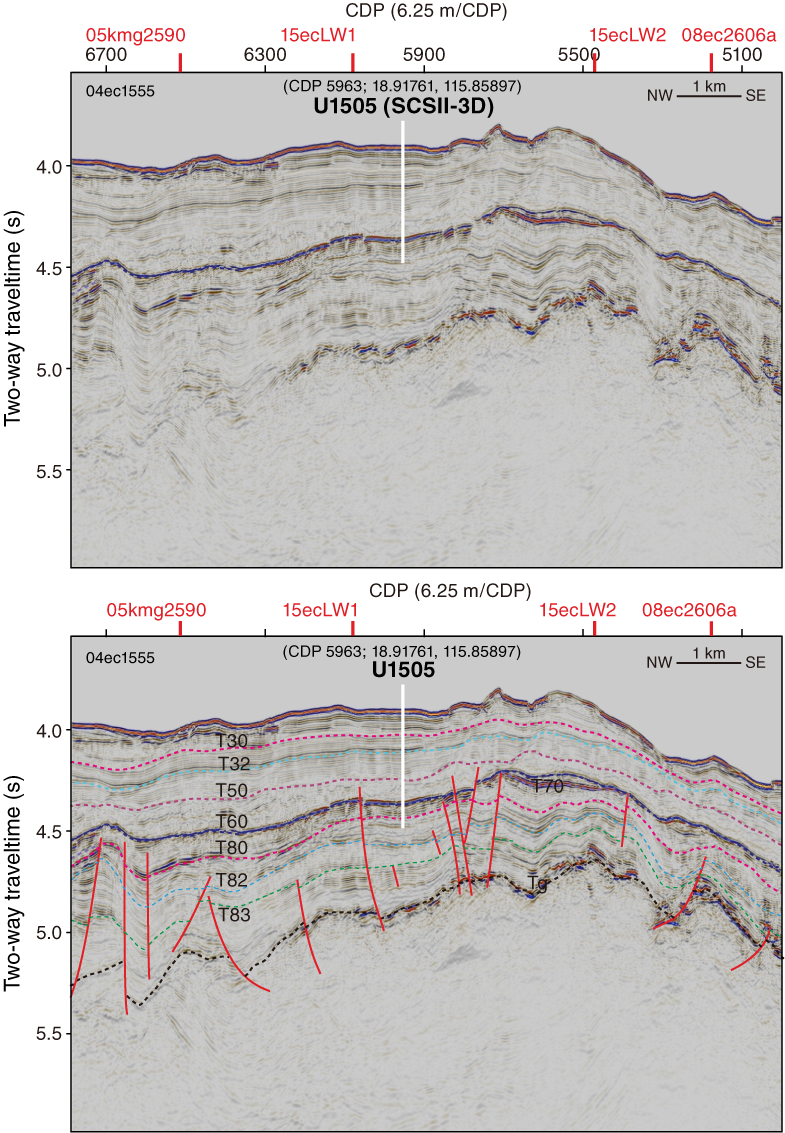
Figure F6. Seismic strike location and penetration depth.
Site U1505 is located near the crossing of seismic Lines 04ec1555 and 15eclLW1 (Figure F1). The predrilling interpretation of the seismic unconformities (T30 to T83 and Tg reflector; see the Expedition 367/368 methods chapter [Sun et al., 2018]) around Site U1505 is shown in Figures F5 and F6. Using the velocity model (see Physical properties and Correlation to seismic data), the sedimentary sequence overlying the acoustic basement is ~1220 m thick. Because of the 3400 m depth limit, the maximum targeted drill depth at Site U1505 was 480 mbsf. The key objective at Site U1505 was to sample the stratigraphic record representing all stages since the T80 unconformity (including prerift sediments through synrift to postrift fill). The specific goal was to constrain the sediment responses to the tectonic events and basin evolution since the Eocene, as well as the Neogene paleoceanographic and paleoclimatological changes at the SCS northern margin.
Sampling sediments from the T80 unconformity (38.0 Ma; inferred age before drilling) to the T60 unconformity (23.0 Ma; inferred age before drilling) will help us determine the environment before the SCS ocean basin formed, particularly the history of paleowater depth changes from shallow water to deep sea. The basin-wide T60 unconformity is a strong negative reflector showing conformable relationships below and above Site U1505. The nature of this profound reflector is an important objective together with the post-T60 stratigraphic interval, which is also expected to provide information to constrain the rate of thermal subsidence following initial tectonic subsidence recorded within the Eocene to early Oligocene sediments.
The younger stratigraphy above the T60 unconformity is the focus of the Neogene environmental development of the SCS and adjacent landmasses of Southeast Asia. The relatively shallow water depth of 2916.6 m at Site U1505 makes it one of the few ODP/IODP sites above the modern CCD of the SCS. Its hemipelagic deposits rich in calcareous microfossils enable the application of stable isotopes, faunal analyses, and other multidisciplinary methods. Key objectives of this interval sampled by a number of ODP/IODP sites are reconstruction of (1) the East Asian monsoonal climate changes of the SCS and surrounding land and (2) upper and deep-water variations in the western Pacific. For the first time, Site U1505 will underpin an almost continuous oxygen isotope sequence at the orbital and millennial timescales since the late Eocene in the SCS. To achieve this goal, relatively complete sediment sequences are required. Double APC holes were designed at this site to establish a continuous record of the Pliocene to Pleistocene interval for high-resolution paleoceanographic study.
Operations
Four holes were cored at Site U1505 (Table T1) using the APC and XCB systems with the objective of recovering a complete sedimentary succession from the early Miocene to Holocene that can supplement the interval sampled at Site U1501 for postexpedition paleoceanographic and paleoclimatological studies. In Hole U1505A (18°55.0560′N, 115°51.5369′E; 2916.6 m water depth), Core 1H misfired (shear pins) and recovered only 0.3 m. In Hole U1505B (18°55.0562′N, 115°51.5370′E; 2918.6 m water depth), Core 1H penetrated 3 m into the seafloor, recovering 3.23 m (107%). With a good mudline core, the hole was terminated. Hole U1505C (18°55.0570′N, 115°51.5370′E; 2917.4 m water depth) was cored to 480.2 m, recovering 480.15 m (100%). Hole U1505D (18°55.0485′N, 115°51.5501′E; 2917.5 m water depth) was cored to 184.5 m, recovering 191.43 m (104%). Downhole logging with a modified triple combo tool was conducted in Hole U1505C.
Table T1. Site U1505 core summary. View table in PDF format. Download table in CSV format.
Transit to Site U1505
The R/V JOIDES Resolution began the transit from Site U1504 to Site U1505 at 1854 h on 28 May 2017 and arrived on site at 2112 h the same day. The thrusters were lowered, and the heading was controlled at 2148 h, beginning operations at Site U1505.
Holes U1505A and U1505B
An APC/XCB bottom-hole assembly (BHA) was made up, and a precision depth recorder (PDR) measurement was taken to help determine the seafloor depth. As the drill string was being lowered to the seafloor, we deployed the subsea camera system to observe the end of the pipe tag the seafloor. APC coring started in Hole U1505A at 0545 h on 29 May 2017 at a water depth of 2916.6 m. With the bit at 2911.2 m, the core barrel was recovered to the surface after an apparent misfire (failed shear pins) of the APC. The barrel had 0.38 m of core, far less than anticipated, and the hole was terminated at 1200 h to attempt a better mudline.
The bit was spaced out to 2912.1 m below sea level (mbsl), and coring in Hole U1505B started at 1235 h on 29 May. The core was recovered with 3.23 m of sediment. With a good mudline core, Hole U1505B was terminated at 1300 h.
Hole U1505C
The vessel was offset 20 m east, and the bit was spaced out to 2916.1 mbsl. Because of a leak in the newly replaced low clutch diaphragm, the decision was made to core with the APC system and then core with the XCB system to refusal or to the maximum drill string weight that could be lifted using the high clutch (whichever came first). Hole U1505C (18°55.0570′N, 115°51.5370′E) was started at 1340 h on 29 May 2017. Seafloor was calculated at 2917.4 mbsl based on recovery from Core 1H. The full-length APC system was used to refusal at 207.1 m with APCT-3 temperature measurements taken on Cores 4H, 7H, 10H, and 13H. All four deployments produced good temperature data. APC refusal was determined after partial strokes on five consecutive cores, beginning with Core 19H and continuing through Core 23H. The half-length APC (HLAPC) system was then deployed and used to recover Cores 24F through 47F. All HLAPC cores were considered partial strokes, with the standpipe retaining pressure after each core. The residual pressure in the standpipe was bled off using the Cameron Orbit valve. HLAPC refusal was determined with recovery of 3.14 m and 2.60 m on Cores 46F and 47F, respectively. While bleeding pressure on Core 47F, the diaphragm on the pneumatic actuation for the Orbit valve failed. The pressure was bled by manually opening the valve, and the valve was taken out of service and repaired.
The XCB system was then deployed and used to core to 480.2 m before reaching the maximum allowable drill string weight dictated the end of coring operations. The hole was displaced using heavy mud, and the bit was raised to 80.1 m in preparation for logging.
A modified triple combo tool string was rigged up and lowered into the hole. The tool string was exceptionally long, consisting of all tools typically run as part of the triple combo (MSS; High-Resolution Laterolog Array [HRLA]; HLDS, with source; HNGS; Enhanced Digital Telemetry Cartridge [EDTC]; and logging equipment head-q tension [LEH-QT]), with the addition of the DSI tool for acoustic velocity. The DSI was added to the first run in anticipation of potential hole problems that might prevent subsequent runs based on experience at nearby sites with similar lithology. The triple combo began collecting data a few meters above the seafloor and recorded continuously to the deepest point the tools could reach, a firm hole obstruction at 341.2 m. The tool string was unable to pass below that depth even after several attempts. Accordingly, the repeat pass was conducted from that depth for a length of ~110 m, and then the main pass was also conducted from that depth up to just above the seafloor. During the run, the triple combo collected NGR, density (with caliper), acoustic velocity, neutron porosity, and magnetic susceptibility data. The caliper indicated that the hole diameter was too large (>14 inches) for effectively collecting useful data with the Formation MicroScanner (FMS) and Versatile Seismic Imager tool strings. Therefore, the decision was made to end downhole logging operations in Hole U1505C. The tools were pulled to the surface after logging was completed and rigged down. The bit was then raised, clearing the seafloor at 1755 h on 2 June and ending Hole U1505C.
Total time spent on Hole U1505C was 103 h (4.3 days). The APC, HLAPC, and XCB systems were deployed in the hole, coring a 480.2 m interval and recovering 480.15 m (100%). The APC system was used to cut 23 cores over a 207.1 m interval with 100% recovery. The HLAPC system was used to cut 24 cores over a 109.9 m interval, recovering 112.9 m (103%). The XCB system recovered 160.4 m of sediment (98%) over a 163.2 m interval. Nonmagnetic core barrels were used on all cores from this hole. All full-length APC cores were oriented. APCT-3 temperature measurements were taken on Cores 4H, 7H, 10H, and 13H.
Hole U1505D
The vessel was offset 20 m south, and the bit was spaced out to 2911.6 m. APC coring in Hole U1505D started at 2200 h on 2 June 2017. Seafloor was calculated at 2917.5 mbsl based on recovery from Core 1H. The hole was cored to a total depth of 184.5 m using only the APC system. The bit was then recovered to the surface, clearing the seafloor at 1800 h and the rotary table at 2310 h on 2 June. The beacon was recovered while raising the pipe and was on deck at 1953 h. The thrusters were raised, and the rig floor was secured for transit. The vessel was underway to return to Site U1504 at 0048 h on 3 June, ending Hole U1505D and Site U1505. Our plan was to use the time remaining on the expedition to drill a second hole to basement at Site U1504.
Overall, 20 APC cores were taken in Hole U1505D over a 184.5 m interval, with 191.43 m recovered (104%). Nonmagnetic core barrels were used for all cores, and all cores were oriented using the Icefield MI-5 core orientation tool.
Lithostratigraphy
We examined the lithostratigraphy in Holes U1505A, U1505C, and U1505D (Figure F7) and defined two lithostratigraphic units. In Hole U1505A, the mudline core misfired (see Operations), and therefore only a 0.33 m interval of the sediment section was recovered. In Hole U1505B, only a mudline core was recovered for educational use, and the core was not described. Hole U1505C was cored to ~480 m using the APC and XCB systems and was used to define the lithostratigraphic unit boundaries. Hole U1505D only recovered the upper section of lithostratigraphic Unit I. Unit I is defined and divided into three subunits based on visual core description, smear slide and thin section inspection, and X-ray diffraction (XRD) analysis (see Lithostratigraphy in the Expedition 367/368 methods chapter [Sun et al., 2018]).
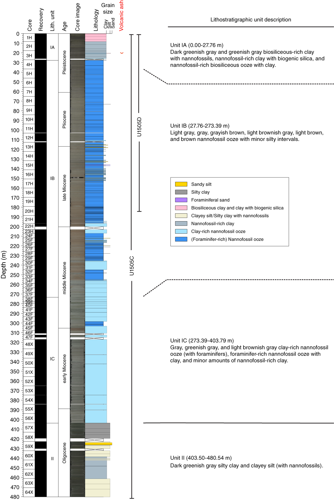
Figure F7. Lithostratigraphic summary.
The sediment succession recovered at Site U1505 extends from 0.00 to 480.54 m (Cores 368-U1505A-1H, 368-U1505C-1H through 64X, and 368-U1505D-1H through 20H).
Unit I is dominated by nannofossil ooze with varying amounts of foraminifers and clay and, in the upper interval of the core, with biogenic silica. The change downhole to Unit II is marked by a sharp change from greenish gray nannofossil ooze (Unit I) to dark greenish gray silty clay and clayey silt with nannofossils (Unit II). The contact between Units I and II occurs between two full-recovery cores but may not have been fully recovered.
Unit description
Unit I
- Intervals: 368-U1505A-1H-1, 0 cm, to 1H-1, 33 cm; 368-U1505C-1H-1, 0 cm, to 56X-CC, 37 cm; 368-U1505D-1H-1, 0 cm, to 20H-CC, 20 cm
- Depths: Hole U1505A = 0–0.33 m; Hole U1505C = 0–403.79 m; Hole U1505D = 0–184.82 m
- Age: Pleistocene–late Oligocene
Lithology and sedimentary structures
Lithostratigraphic Unit I is dominated by nannofossil ooze with varying amounts of foraminifers and clay. The upper part is biosiliceous-rich clay (Figure F8D) with minor nannofossil-rich biosiliceous ooze with clay. The unit is divided into three subunits, IA–IC, based on changes in the biogenic component of the sediment and color changes that coincide with subtle changes in the sediment components.
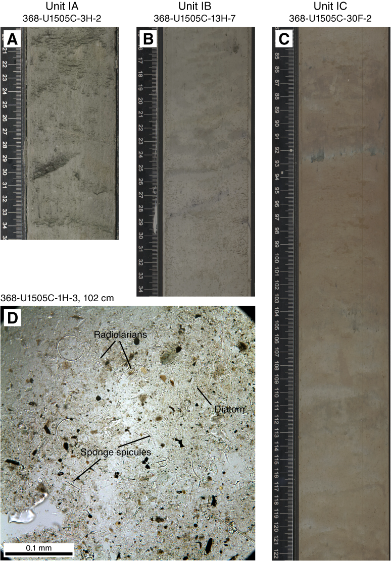
Figure F8. Representative core section images.
The boundary between Units I and II is marked by a sharp change in lithology from nannofossil ooze–dominated sediments to silt and clay–dominated sediments.
Bulk mineralogy and chemistry
The bulk mineralogy results of XRD analyses are listed in Table T2 and shown in Figure F9, which also shows the downcore variations in the relative abundance of minerals in bulk sediments at Site U1505. Unit I sediment is composed mainly of calcite, quartz, plagioclase, halite, and pyrite, as well as K-feldspar and clay minerals, including smectite, illite, kaolinite, and chlorite. In general, the percentages of halite and most terrigenous minerals in Unit I, including quartz, plagioclase, K-feldspar, and clay minerals (illite, kaolinite, and chlorite) decrease downhole, whereas calcite and pyrite increase.
Table T2. Mineral percentages. View table in PDF format. Download table in CSV format.
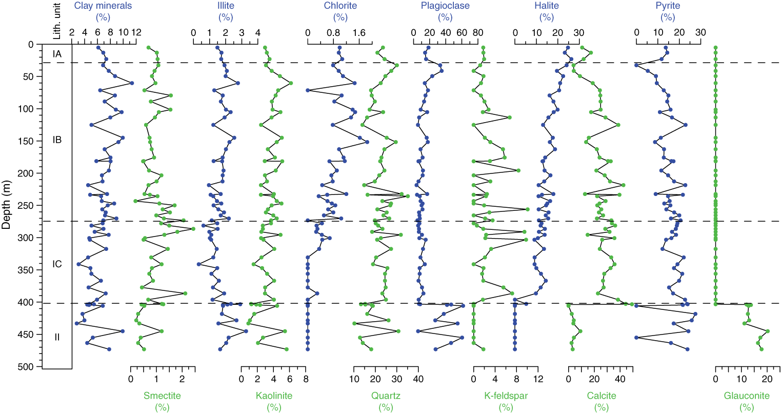
Figure F9. Bulk mineralogy.
Compositional analyses of the nannofossil ooze in Sections 368-U1505C-56X-7 and 56X-CC (Subunit IC) were made directly on the archive half of the core using the handheld portable X-ray fluorescence spectrometer (pXRF) (see Igneous and metamorphic petrology in the Expedition 367/368 methods chapter [Sun et al., 2018]) to examine in detail the transition between Units I and II (Table T3). The 16 intervals analyzed in Unit I show no variation in composition, with CaO contents of ~30 wt%, SiO2 contents of ~20–24 wt%, and lower Al2O3 (~5 wt%), Fe2O3 (<3 wt%), and MgO (<2 wt%) abundances. The ooze has Sr contents between 700 and 800 ppm and Zr contents between 50 and 60 ppm.
Table T3. Bulk chemistry data obtained from shipboard handheld portable X-ray fluorescence analysis. View table in PDF format. Download table in CSV format.
Subunit IA
- Intervals: 368-U1505A-1H-1, 0–33 cm; 368-U1505C-1H-1, 0 cm, to 4H-1, 56 cm; 368-U1505D-1H-1, 0 cm, to 4H-3, 150 cm
- Depths: Hole U1505A = 0–0.33 m; Hole U1505C = 0–27.76 m; Hole U1505D = 0–27.50 m
- Age: Pleistocene
Subunit IA spans the recovered uppermost 27.76 m in Hole U1505C and 27.50 m in Hole U1505D and is dominated by dark greenish gray and greenish gray biosiliceous-rich clay with nannofossils, nannofossil-rich clay with biogenic silica, and nannofossil-rich biosiliceous ooze with clay (Figure F8A). The abundance of biogenic silica decreases downhole. The fine-grained component comprises nannofossils, foraminifers, diatoms, sponge spicules, radiolarians, and terrigenous grains, including clay minerals, and rare quartz and feldspar (Figure F8D). The sediment is well sorted and unlithified. The average grain size is clay, and very fine sand is the maximum grain size. Bioturbation is heavy (Figure F8A).
A pinkish gray, ~6 cm thick, slightly normally graded ash layer was found in interval 368-U1505C-3H-3, 24–32 cm (Figure F10A), and ash pods were found at the corresponding depth in Hole U1505D in interval U1505D-3H-5, 83–86 cm (Figure F10B).
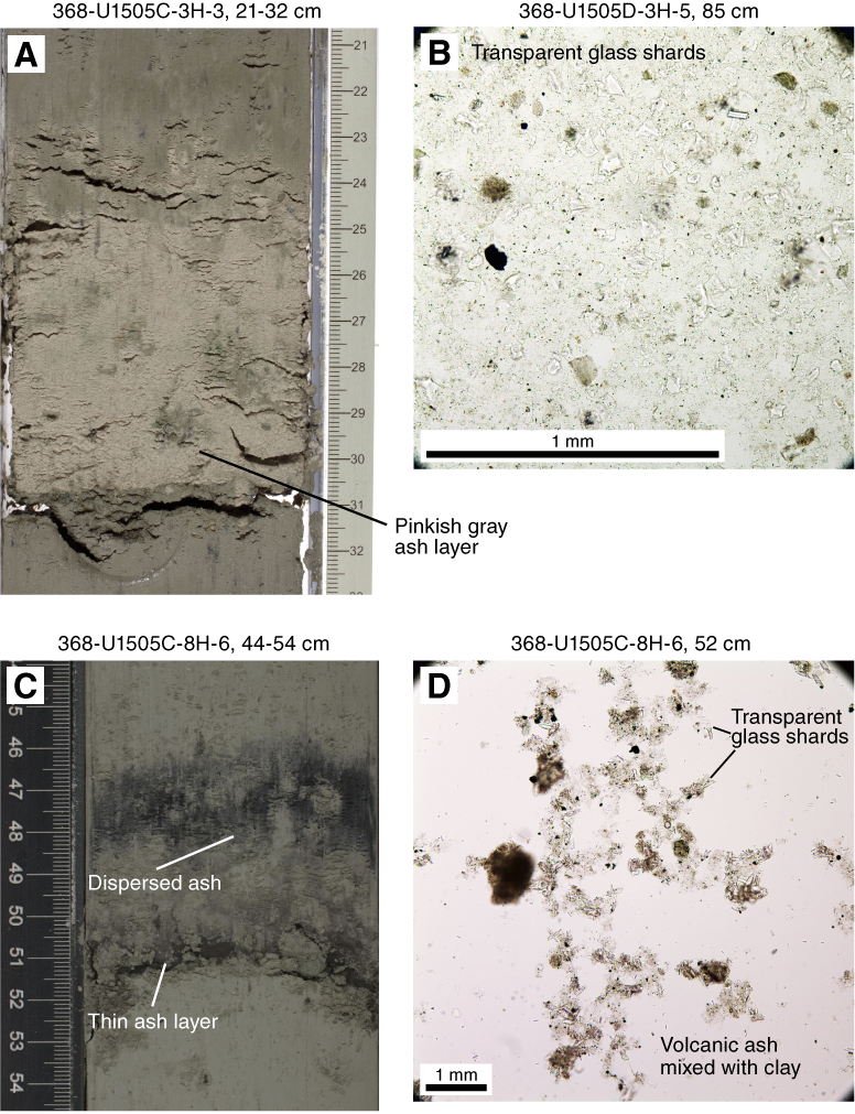
Figure F10. Pinkish gray ash layer.
The base of Subunit IA is marked by both a color change from dark greenish gray to dark gray sediment in Subunit IB and by a lithologic change that reflects an increase in the percentage of foraminifers.
Subunit IB
- Intervals: 368-U1505C-4H-1, 56 cm, to 38F-1, 49 cm; 368-U1505D-4H-4, 0 cm, to 20H-CC, 20 cm
- Depths: Hole U1505C = 27.76–273.39 m; Hole U1505D = 27.50–184.82
- Age: Pleistocene to middle Miocene
Subunit IB is 245.63 m thick and comprises light gray, gray, grayish brown, light brownish gray, light brown, and brown nannofossil ooze with minor silty intervals (Figure F8B). The color change reflects the varying abundance of foraminifers and clay. The sediment is well sorted and slightly consolidated. The sediment structure is massive. The average grain size is clay, and medium sand is the maximum grain size. Boundaries are subhorizontal, horizontal, or inclined. Bioturbation is moderate to heavy. Thin, silty, fining-upward intervals with erosive bottom contacts are common in Subunit IB (Figure F11). One ~5 cm thick very dark greenish gray ash layer with a dispersed top and a sharp basal contact is found in interval 368-U1505C-8H-6, 47–52 cm (Figure F10C, F10D). Pyrite patches are common.
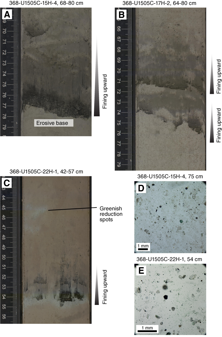
Figure F11. Fining-upward interval.
From Core 19H downhole, basal flow-in destroys the sediment structures (Figure F12).

Figure F12. Destruction of sedimentary features.
The boundary between Subunits IB and IC is defined by the first occurrence of burrows of Zoophycos.
Subunit IC
- Interval: 368-U1505C-38F-1, 49 cm, to 56X-CC, 37 cm
- Depth: 273.39–403.79 m
- Age: middle Miocene to late Oligocene
Subunit IC is 130.40 m thick and composed of gray, greenish gray, and light brownish gray clay-rich nannofossil ooze (with foraminifers), foraminifer-rich nannofossil ooze with clay, and minor amounts of nannofossil-rich clay (Figure F8C). The sediment is well sorted and well consolidated. The average grain size is clay, and very fine sand is the maximum grain size.
Contacts between layers are often bioturbated or gradational, horizontal to subhorizontal, or inclined. The bioturbation in Subunit IC sediment is heavy to complete. Greenish reduction spots are common and are related to burrows. Burrows are often filled with foraminifers and are dark gray in color. The trace fossil assemblage includes Chondrites, Thalassinoides, Planolites, and Zoophycos (Figure F13).
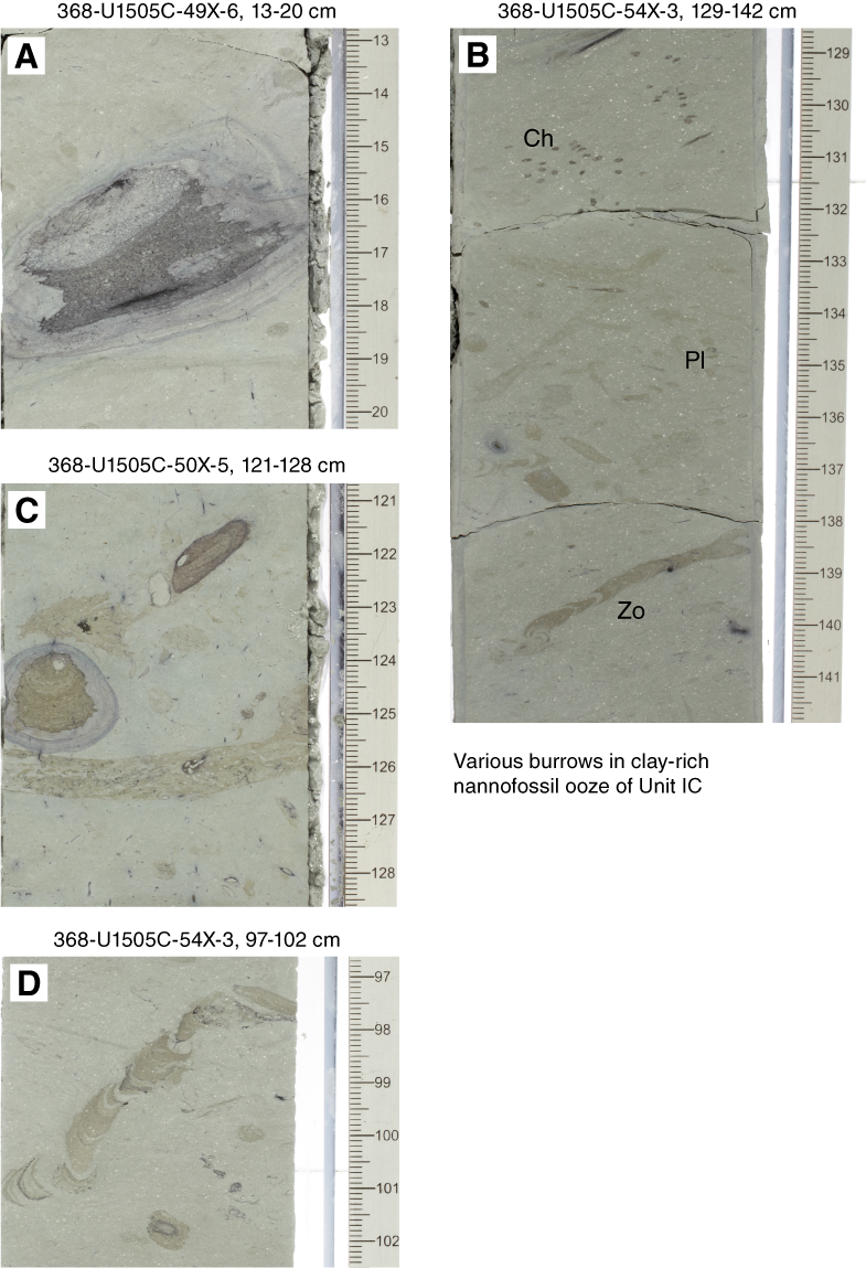
Figure F13. Typical ichnospecies.
Compositional analyses of the ooze in Subunit IC were made directly on the archive half of the core using the handheld pXRF instrument (see Igneous and metamorphic petrology in the Expedition 367/368 methods chapter [Sun et al., 2018]) (Table T3). The ooze (16 analyses) in Sections 368-U1505C-56X-7 and 56X-CC shows only minor variation in bulk composition. The major components are CaO (28–35 wt%), SiO2 (18–25 wt%), and Al2O3 (4–6 wt%). The ooze has Sr contents of 730–840 ppm.
The boundary between Subunit IC and Unit II is characterized by a sharp change from greenish gray clay-rich nannofossil ooze to very dark greenish gray silty clay.
Unit II
Lithology and sedimentary structures
Unit II is dominated by dark greenish gray, well-consolidated silty clay and clayey silt (with nannofossils). The amount of nannofossils increases downhole (nannofossil-rich silty clay and clayey silt with nannofossils) to Core 368-U1505C-62X and then decreases in Cores 63X and 64X. The average grain size is silt and clay, and fine to medium sand is the maximum grain size. The sediment is thinly laminated. Bioturbation is heavy, and foraminifers and shell fragments are common (Figure F14E). Pyrite forms up to centimeter-sized patches, and rare concentrations of organic matter were also observed (Figure F14C, F14D). Glauconite grains are especially abundant in Sections 58X-4 (Figure F14A, F14B) and 59X-2.

Figure F14. Special features.
Bulk mineralogy and chemistry
The bulk mineralogy results of XRD analyses are listed in Table T2. Unit II sediments are composed mainly of glauconite, quartz, plagioclase, clay minerals (including smectite, illite, and kaolinite), and minor amounts of pyrite and calcite. Figure F9 shows the downhole variations in the relative abundance of minerals identified by XRD in bulk sediments at Site U1505. Compared to Unit I, Unit II shows distinctly higher percentages of glauconite, plagioclase, kaolinite, and illite. In contrast, Unit II sediments have lower percentages of calcite, halite, K-feldspar, chlorite, and smectite.
Compositional analyses of Unit II clay were made directly on the archive half of the core using the handheld pXRF instrument (see Igneous and metamorphic petrology in the Expedition 367/368 methods chapter [Sun et al., 2018]) (Table T2). The clay (eight analyses) in Section 368-U1505C-57X-1 shows little variation in bulk composition. The major components are SiO2 (~45 wt%), Al2O3 (12–16 wt%), and minor MgO (2–4 wt%) and K2O (~2 wt%). The clay has Sr contents of ~150 ppm and Zr contents of ~80 ppm.
Discussion
Depositional environment of Unit II
Unit II was most likely deposited in a moderately deep water (upper slope) marine-depositional environment based on the high clay content, abundance of nannofossils, and presence of glauconite. In general, the sediment is fine grained (silty clay) and dominated by terrigenous materials (quartz, feldspar, and clay minerals), with lesser calcareous microfossils, including nannofossils and foraminifers, minor authigenic glauconite and calcite, and rare radiolarians. Small shelly fragments, microfossils, and organic fragments are visible on the core surface, along with occasional macrofossils, including bivalves.
Glauconite grains are present between Sections 368-U1505C-58X-4 and 62X-6. The presence of glauconite indicates that the sediment was most likely deposited at temperatures ranging from 7°C to 15°C (Margielewski et al., 2017) in low oxygen conditions and in shelf to lower slope environments from 20 to 700 m water depth (e.g., Drzewiecki and Simo, 2002; Margielewski et al., 2017).
Depositional environment of Unit I
Lithostratigraphic Unit I was deposited in a deep-marine environment. The dominant lithology is nannofossil ooze with variable amounts of clay and foraminifers. The top of Unit I is more clay rich and contains siliceous microfossils. Lithologic differences between subunits likely reflect changes in the amount of terrigenous input into a relatively open ocean setting, climate change, and changes in oceanographic conditions. The terrigenous input may be delivered as buoyant plumes from shallower shelf environments and rarely by weak (distal) turbidity currents. There is little change in the composition of the terrigenous grains through Unit I, so we envisage a similar source for these grains. Thin laminae of silt, often with pyrite, are found sparsely throughout Unit I. Some are graded, and all have sharp bases; however, many are disrupted by bioturbation and interpreted as distal turbidites.
Preliminary correlation between Units I and II at Sites U1501, U1504, and U1505
Site U1501 is located 50.28 km west of Site U1504 on the OMH. Site U1505 is in the vicinity of Site U1501 (10.46 km east). Today’s water depths are very similar at Sites U1501, U1504, and U1505 (2857, 2816, and 2917 mbsl, respectively). The recovered Pleistocene to early Miocene/Oligocene sediment successions can be correlated based on their major lithologies and the age of deposition. We suggest a correlation between Pleistocene Subunit IA (Site U1505), Pleistocene Subunit IA (Site U1504), and Pleistocene to Pliocene Subunits IA and IB (Site U1501) because all are dominated by dark greenish gray nannofossil-rich clay and clay-rich nannofossil-ooze with siliceous microfossils. At Site U1504, there seems to be a hiatus below Subunit IA (see Biostratigraphy). Between Sites U1504 and U1501, middle Miocene Subunit IB (Site U1504) correlates well with late to middle Miocene Subunit IC (Site U1501). These subunits are both composed of greenish gray and light brownish gray nannofossil ooze with clay- and foraminifer-rich intervals. Middle Miocene Subunit IC (Site U1504) can be correlated with middle Miocene to Oligocene Subunits ID and IE (Site U1501). These subunits are characterized by greenish gray and gray nannofossil ooze with clay.
Despite being close to Site U1501, the lack of distinct boundaries in the lithology at Site U1505 makes correlation between these sites difficult. Pleistocene to late Oligocene Subunits IB and IC (Site U1505) correlate in time to Subunits IC–IF at Site U1501 and Subunit IB and Unit II at Site U1504. In addition, although there is a change from brownish to grayish layers at Site U1505, as was observed at Sites U1501 and U1504, the color changes are more subtle and without clear boundaries, making correlation difficult. Therefore, a more detailed correlation of the post-Oligocene sediments between the three sites will require postexpedition research.
Unit II at Site U1505 correlates well with Unit II at Site U1501. There is an unconformity at the boundary between Unit I and Unit II at Site U1501 and a sharp lithologic boundary between the two units at Site U1505. The carbonate-to-clay ratio abruptly changes at this boundary at both sites, and Unit I has more abundant calcareous microfossils than Unit II. The sedimentation rate is very low below the Unit II/I boundary at both sites (see Biostratigraphy).
Structural geology
Site U1505 is located on the OMH at a water depth of 2917 m roughly 10 km from Site U1501. The sedimentary and structural record at these two sites is very similar.
Lithostratigraphic Unit I structures
Lithostratigraphic Unit I, which consists of nannofossil oozes, shows predominantly horizontal to subhorizontal bedding that in most cases is erased due to moderate to strong bioturbation and drilling disturbance. Unit I is devoid of any visible structures related to tectonic deformation.
Lithostratigraphic Unit II structures
Lithostratigraphic Unit II is characterized by subhorizontal to gently dipping bedding as shallow as 10°. Similar to Site U1501, some minor deformation structures are heterogeneously distributed within Unit II. In Core 368-U1505C-60X (Figure F15), millimeter-scale normal faults and joints show comparable geometries to those described in Structural geology in the Site U1501 chapter (Larsen et al., 2018a). In most cases, these deformation structures are overprinted by drilling disturbance, making their recognition difficult.
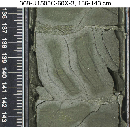
Figure F15. Deformation structures.
Biostratigraphy
All core catcher samples from Holes U1505A, U1505B, and U1505C were analyzed for calcareous nannofossils, planktonic foraminifers, and diatoms. Additional samples were taken from intervals within the working-half cores when necessary to refine the ages. Preservation of calcareous microfossils is good in Cores 368-U1505C-1H through 48X and moderate to poor in Cores 49X through 64X. Planktonic foraminifers are abundant or common in Cores 1H through 56X and 59X through 62X and few or rare in Cores 57X, 58X, 63X, and 64X. Calcareous nannofossils are generally abundant to common in most samples from Hole U1505C, except in the upper part of Core 57X, where they are rare to absent.
Forty-five biostratigraphic datums identified in Hole U1505C suggest a continuous succession of early Oligocene to Holocene age (Tables T4, T5; Figure F16). The Pleistocene/Pliocene boundary was placed within Core 7H, the Pliocene/Miocene boundary between Cores 11H and 13H, and the Miocene/Oligocene boundary between Cores 54X and 55X. Sedimentation rates vary from ~7 mm/ky in the Oligocene to ~15 mm/ky during the Miocene–Pliocene and ~24 mm/ky during the Pleistocene.
Table T4. Calcareous nannofossil events. Download table in CSV format.
Table T5. Planktonic foraminifer events. Download table in CSV format.

Figure F16. Age-depth model.
Relatively lower planktonic foraminifer content below Core 57X indicates a shoaling marine environment during the early Oligocene, whereas much higher abundances of planktonic foraminifers above Core 56X suggest a deep-water environment since the late Oligocene.
Calcareous nannofossils
Core catchers from Holes U1505A, U1505B, and U1505C were examined (Table T6). Calcareous nannofossil biostratigraphy for Site U1505 was based mainly on the analysis of all core catcher samples from Hole U1505C, and a number of samples from intervals within cores were analyzed to better constrain the biostratigraphic events.
Table T6. Calcareous nannofossils. View table in PDF format. Download table in CSV format.
Nannofossils are abundant to common in most samples from Hole U1505C with the exception of those from the upper part of Core 57X. They are barren in Samples 57X-1, 0–1 cm, and 57X-1, 24–25 cm, rare in Sample 57X-1, 144–145 cm, and resume common to abundant occurrences below Sample 57X-6, 1–2 cm. These occurrences indicate a significant change in nannofossil abundance between Samples 57X-1, 144–145 cm, and 57X-6, 1–2 cm.
Nannofossil preservation is good in most samples from Hole U1505C with the exception of Samples 52X-CC to 60X-CC. In this interval, discoasterids and Sphenolithus show slight to heavy overgrowth.
Twenty-seven nannofossil biostratigraphic datums were recognized in the Oligocene through Pleistocene sediment sequence (Table T4). The oldest nannofossil event identified at Site U1505 is the last appearance datum (LAD) of Reticulofenestra umbilicus, which occurs at 430.26 m in Hole U1505C and indicates an age older than 32.02 Ma.
Pleistocene
The top of Hole U1505C (Samples 1H-CC to 2H-CC; 17.74 m) is dated as late Pleistocene based on the presence of Emiliania huxleyi (marker species for Zone NN21). The LAD of Pseudoemiliania lacunosa in Sample 4H-CC (37.17 m) defines the top of Zone NN19. Zone NN19 is further divided by two nannofossil events, the first appearance datum (FAD) of Gephyrocapsa spp. >4 µm reentrance in Sample 5H-CC (46.51 m) and the LAD of Calcidiscus macintyrei in Sample 6H-CC (56.23 m).
Pliocene
Pliocene nannofossil Zones NN16, NN15, and NN12 were recognized in Hole U1505C. Two events occur in the lower part of Zone NN16: the LAD of Discoaster tamalis (2.8 Ma) in Sample 7H-CC (65.70 m) and the LAD of Sphenolithus spp. (3.54 Ma) in Sample 8H-CC (74.95 m). The LAD of Reticulofenestra pseudoumbilicus (3.70 Ma) in Sample 9H-CC (84.18 m) defines the top of Zone NN15. The LAD of Ceratolithus acutus (5.04 Ma) in Sample 11H-CC (102.78 m) defines the top of Zone NN12. The Pliocene/Miocene boundary in Hole U1505C was placed between Samples 11H-CC (102.78 m) and 13H-CC (122.71 m) based on the LADs of C. acutus and Nicklithus amplificus, respectively.
Miocene
Seven events occur in the late Miocene strata of Hole U1505C. Zone NN11 includes three events: the LAD of N. amplificus (5.94 Ma) in Sample 13H-CC (122.71 m), the FAD of N. amplificus (6.91 Ma) in Sample 14H-CC (132.23 m), and the FAD of Discoaster berggrenii (8.29 Ma) in Sample 16H-CC (150.90 m). The LAD of Discoaster bollii (9.21 Ma) in Sample 18H-CC (170.28 m) falls within Zone NN10. The LAD (9.53 Ma) and FAD (10.55 Ma) of Discoaster hamatus, which occur in Samples 19H-CC (179.75 m) and 20H-CC (189.26 m), respectively, define Zone NN9. The FAD of Catinaster coalitus (10.89 Ma) was used to mark the base of Zone NN8, which occurs in Sample 21H-CC (196.53 m). The late/middle Miocene boundary in Hole U1501C was assigned between Samples 21H-CC (196.53 m) and 23H-CC (207.05 m) based on the FAD of C. coalitus (10.89 Ma) and the LAD of Cyclicargolithus floridanus (11.85 Ma), respectively.
Five events are recorded in the middle Miocene strata of Hole U1505C. The top of Zone NN6 is marked by the LAD of C. floridanus (11.85 Ma) in Sample 23H-CC (207.05 m). Two additional events were found in Zone NN6: the LAD of Coronocyclus nitescens (12.12 Ma) in Sample 25F-CC (216.92 m) and the FAD of R. pseudoumbilicus (12.83 Ma) in Sample 28F-CC (230.93 m). The top of Zone NN5 is marked by the LAD of Sphenolithus heteromorphus (13.53 Ma) in Sample 29F-CC (235.69 m). The top of Zone NN4 is defined by the LAD of Helicosphaera ampliaperta (14.91 Ma) in Sample 35F-CC (263.83 m). The middle/early Miocene boundary was assigned between Samples 35F-CC (263.83 m) and 47F-CC (314.90 m).
Three events were recognized in the early Miocene strata of Hole U1505C. The top of Zone NN2 is marked by the LAD of Triquetrorhabdulus carinatus (18.28 Ma) in Sample 47F-CC (314.90 m). The bottom of Zone NN2 is defined by the FAD of Sphenolithus disbelemnos (22.76 Ma), which occurs in Sample 53X-CC (374.57 m). One additional event, the FAD of H. ampliaperta (20.43 Ma) within Zone NN2, was found in Sample 48X-CC (326.93 m). The Miocene/Oligocene boundary was assigned between Samples 53X-CC (374.57 m) and 55X-CC (394.11 m) based on the FAD of S. disbelemnos (22.76 Ma) and the LAD of Reticulofenestra bisecta >10 µm (23.13 Ma), respectively.
Oligocene
Four events were identified in the Oligocene strata of Hole U1505C. The top of Zone NP25 is marked by the LAD of R. bisecta (>10 µm; 23.13 Ma) in Sample 55X-CC (394.11 m). The LAD of Sphenolithus ciperoensis (24.43 Ma) within Zone NP25 occurs in Sample 56X-CC (403.84 m). The top of Zone NP24 was recognized by the LAD of Sphenolithus predistentus (26.93 Ma) in Sample 57X-6, 1–2 cm (411.07 m). The top of Zone NP22 is marked by the LAD of R. umbilicus (32.02 Ma) in Sample 59X-CC (430.26 m).
Nannofossil assemblages in Samples 59X-CC through 64X-CC are characterized by relatively abundant Braarudosphaera bigelowii, Helicosphaera bramlettei, Helicosphaera compacta, and Pontosphaera spp. In particular, a significant portion of the nannofossil assemblage is composed of some late Eocene or older species such as Pontosphaera exilis, Pontosphaera pectinata, Pontosphaera pulchripora, Reticulofenestra erbae, Reticulofenestra cf. reticulata, Reticulofenestra isabellae, and Reticulofenestra westerholdii, suggesting that the age of the bottom of Hole U1505C is possibly the late Eocene. This evaluation warrants quantitative study during postcruise research because the definition of the late Eocene nannofossil zonation is based on their changes in abundance.
Planktonic foraminifers
All core catcher samples and several additional samples from the split cores from Holes U1505A, U1505B, and U1505C were processed for planktonic foraminiferal analyses (Tables T7). Planktonic foraminifers are well preserved and abundant in Cores 368-U1505C-1H through 48X and moderately preserved and few in Cores 49X through 64X, except for the poorly preserved and rare condition in Cores 57X to 58X.
Table T7. Planktonic foraminifers. View table in PDF format. Download table in CSV format.
Only mudline cores were recovered from Holes U1505A and U1505B. No pink Globigerinoides ruber specimens were found in Samples 368-U1505A-1H-CC and 368-U1505B-1H-CC. Compared to the planktonic foraminiferal occurrence in Hole U1505C, the bottom age of Holes U1505A and U1505B might be younger than 0.12 Ma.
Eighteen planktonic foraminiferal datums were recognized in Hole U1505C, spanning from the early Oligocene (>32.03 Ma) to the late Pleistocene (Table T5). The planktonic foraminiferal biostratigraphy for Hole U1505C was established by these events and the planktonic foraminiferal assemblages at successive depth intervals.
The Pleistocene planktonic foraminifers are composed of G. ruber, Globigerinoides sacculifer, Globorotalia menardii, Pulleniatina obliquiloculata, and Neogloboquadrina dutertrei. The LAD of pink G. ruber (0.12 Ma) and the FAD of pink G. ruber acme (0.40 Ma) occur between Samples 368-U1505C-1H-CC and 2H-CC and Samples 3H-CC and 4H-CC, respectively. The LAD of Globorotalia tosaensis (0.61 Ma) is located between Samples 4H-CC and 5H-CC. The LAD of Globorotalia multicamerata (2.18 Ma) is located between Samples 6H-CC and 7H-CC.
The Pliocene planktonic foraminiferal assemblage is characterized by the higher content of Dentoglobigerina altispira and Sphaeroidinellopsis seminulina. The LAD of S. seminulina (3.59 Ma) is located between Samples 7H-CC and 8H-CC. The LAD of Globoturborotalita nepenthes (4.37 Ma) is located between Samples 9H-CC and 10H-CC and defines the boundary of Zones N20 and N19.
The late Miocene foraminiferal assemblage is dominated by D. altispira, S. seminulina, G. menardii, Globoquadrina venezuelana, and Globoquadrina dehiscens. The LAD of G. dehiscens (5.92 Ma) is located between Samples 17H-CC and 18H-CC and defines the boundary of Zones N18 and N17. The FAD of Paragloborotalia mayeri (10.46 Ma) is located between Samples 20H-CC and 21H-CC and defines the boundary of Zones N15 and N14.
The middle Miocene foraminiferal assemblage is dominated by D. altispira, S. seminulina, G. venezuelana, G. dehiscens, and Praeorbulina spp. The FAD of G. nepenthes (11.63 Ma) and the LAD of Fohsella fohsi (11.79 Ma) are both located between Samples 25H-CC and 26H-CC and define the boundary of Zones N13 and N12 (i.e., boundary of the late/middle Miocene). The LAD of Praeorbulina circularis (14.89 Ma) is located between Samples 33F-CC and 34F-CC.
The late Oligocene–early Miocene planktonic foraminifers are characterized by G. dehiscens, G. venezuelana, Catapsydrax dissimilis, and P. mayeri. The FAD of Praeorbulina sicana (16.38 Ma) is located between Samples 44F-CC and 45F-CC and marks the boundary of Zones N8 and N7. The LAD of C. dissimilis (17.54 Ma) is located between Samples 47F-CC and 48F-CC and indicates the boundary of Zones N7 and N6. The LAD of Globoquadrina binaiensis (19.09 Ma) is located between Samples 48F-CC and 49F-CC. The LAD of Paragloborotalia kugleri (21.12 Ma) is located between Samples 50X-CC and 51X-CC as the boundary of Zones N5/N4. The LAD of Globigerina ciperoensis (22.90 Ma) is located between Samples 53X-CC and 54X-CC and represents the Miocene/Oligocene boundary.
The early Oligocene planktonic foraminifers are characterized by Paragloborotalia nana/opima, Turborotalia ampliapertura, and G. ciperoensis. The LAD of P. opima (26.93 Ma) is located between Samples 56X-CC and 57-CC as the boundary of Zones P22/P21. The LAD of T. ampliapertura (30.28 Ma) is located between Samples 58X-CC and 59X-CC as the boundary of Zones P20/P19.
The relative abundance of planktonic foraminifers decreases below Core 56X, clearly indicating a shallower water environment during the late to early Oligocene.
Diatoms
The core catcher samples from Hole U1505C were processed into smear and strewn slides for diatom analysis. A total of 28 additional toothpick samples were taken from selected intervals of the working-half cores for better resolution. Samples from the mudline to Sample 3H-CC are composed of between 1% and 50% diatoms with poor preservation (Table T8). The rest of the samples, with the exception of Samples 63X-CC and 64X-CC, were barren of diatoms.
Table T8. Diatoms. View table in PDF format. Download table in CSV format.
Samples 1H-CC, 2H-CC, and 3H-CC contain a typical late Pleistocene tropical–subtropical diatom assemblage such as Fragilariopsis doliolus and Nitzschia interruptestriata (Table T9). Fragilariopsis reinholdii (LAD = 0.62 Ma) was not observed in Sample 4R-CC, suggesting an age younger than 0.62 Ma.
Table T9. Diatom event. Download table in CSV format.
Smear slides from Samples 63X-CC and 64X-CC are devoid of diatoms, but the washed residues for foraminiferal analysis contain a few specimens of large (~250 µm) heavily recrystallized diatoms that are similar to Arachnoidiscus in appearance.
Paleomagnetism
Shipboard measurements
Shipboard paleomagnetic investigations on Hole U1505C cores combined two complementary approaches (see Paleomagnetism in the Expedition 367/368 methods chapter [Sun et al., 2018]): (1) measurement of archive-half sections on the pass-through 2G Enterprises SRM at 2.5 cm spacing and (2) measurement and AF demagnetization of 55 oriented discrete samples on the spinner magnetometer (AGICO JR-6A). Additionally, the anisotropy of magnetic susceptibility (AMS) was measured on discrete samples with the KLY 4 Kappabridge.
Except for Sections 368-U1505C-1H-1 through 3H-1, which were in-line AF demagnetized in 3 steps (5, 10, and 15 mT), only NRM was measured with the SRM for Hole U1505C. This decision was made after a comparison of magnetization intensities between discrete samples and sections led us to suspect that the SRM was not properly calibrated (geometrically) for core sections. U-channel samples will be collected on shore to analyze and demagnetize this core.
Scalar data from discrete samples from AF demagnetization up to 120 mT were used to assess the nature of the magnetic assemblage and the directional and intensity data. Directional data were analyzed using Zijderveld diagrams (Zijderveld, 1967), and the characteristic remanent magnetization (ChRM) direction(s) were calculated by principal component analysis (PCA) (Kirschvink, 1980) using PuffinPlot (version 1.03, April 23, 2015) (Lurcock and Wilson, 2012).
Demagnetization behavior and implications for magnetic assemblages
- Units: lithostratigraphic Units I and II
- Depth: 0.00–480.54 m
- Sections 368-U1505C-1H-1 through 64X-CC
Most of the 55 discrete samples investigated show very soft magnetic behavior characterized by loss of more than 60% of NRM below 15 mT. This very low coercivity (soft behavior) is the reason for the strong vertical drilling overprint (average inclination ≈ 81°) that is particularly visible in the APC cores. The drilling overprint is easily removed by demagnetization to 10–15 mT (Figure F17). The soft behavior shows that magnetic remanence is dominated by titanomagnetite or magnetite. The contribution of greigite to the magnetic assemblages is visible in a few discrete specimens between Cores 368-U1505C-11H and 17H through a minute increase in magnetization above 70 mT. The lower part of the hole (Cores 48X through 64X) is characterized by severe drilling disturbance, resulting in destruction of the NRM vector, which is visible in the scatter of inclinations (Figure F18). The drilling overprint affects discrete samples (yellow squares in Figure F19) far less than core sections (blue crosses).
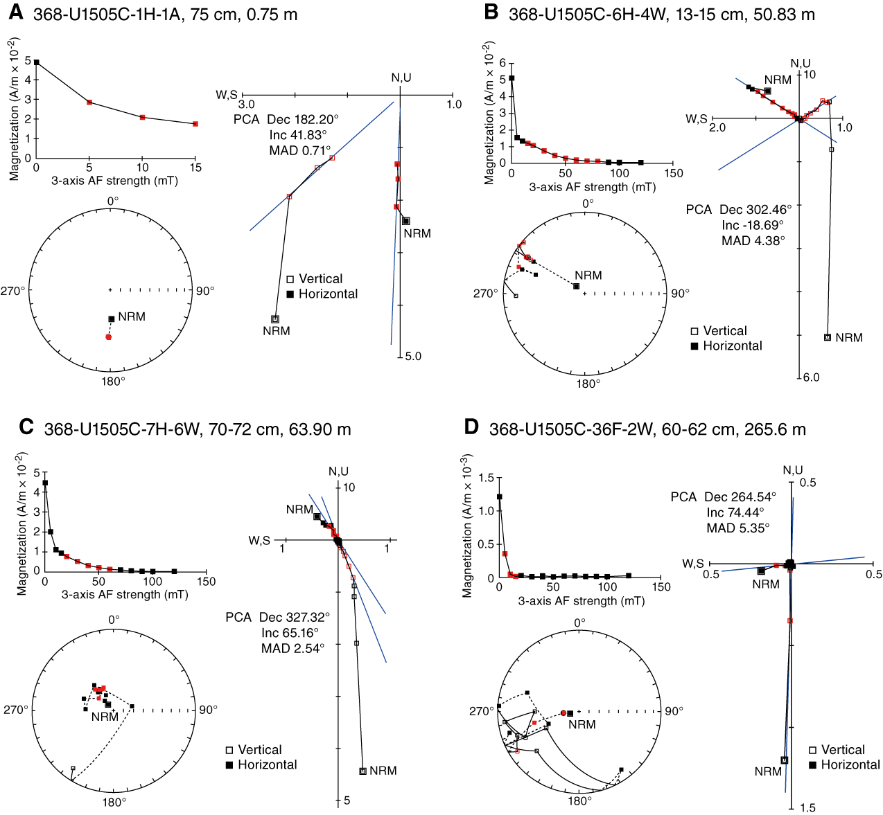
Figure F17. AF demagnetization.
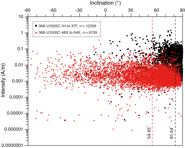
Figure F18. Magnetization intensity vs. inclination.
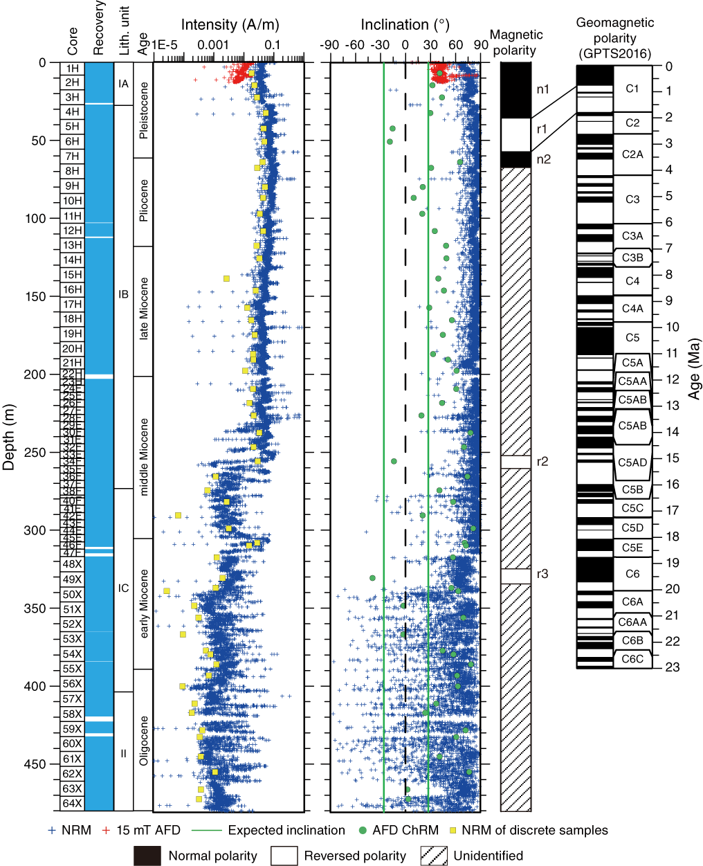
Figure F19. Magnetic measurements.
Magnetostratigraphy
Inclination, intensity, and polarity for Hole U1505C are reported in Figure F19. We constructed the magnetostratigraphy based on the polarity assigned to the archive-half cores and corroborated by directions obtained from oriented discrete samples. A succession of two normal and three reversed polarities was recognized. We tentatively correlated the magnetostratigraphic data of Site U1505C with the standard timescale (Ogg et al., 2016) according to biostratigraphy age constraints as reported in Figure F16. The normal polarity Zone n1 is interpreted as the Brunhes Chron (C1n), with the lower boundary at 37.415 m with an age of 0.781 Ma. The lower boundary (57.365 m) of reversed Polarity r1 is the base of Subchron C1r.3r with an age of 1.778 Ma.
Anisotropy of magnetic susceptibility
The 55 discrete samples have magnetic susceptibility (κ) values ranging from ≈ 60 × 10−6 to 628 × 10−6 SI (Figure F20). These low κ values combined with the low NRM suggest that both paramagnetic silicates (e.g., clays and chlorite) and minor ferromagnetic phases (e.g., titanomagnetite or magnetite) control the magnetic susceptibility. The degree of magnetic anisotropy (P′) is moderate (~1.025), whereas the AMS fabric has a strongly oblate fabric, as shown by shape parameter (T), most likely of depositional origin. The Fisher distribution of AMS principal axes also suggests an oblate fabric with a nearly horizontal planar fabric. These sedimentary fabrics are consistent with deposition in a calm, pelagic environment with very limited traction on sedimentary particles.
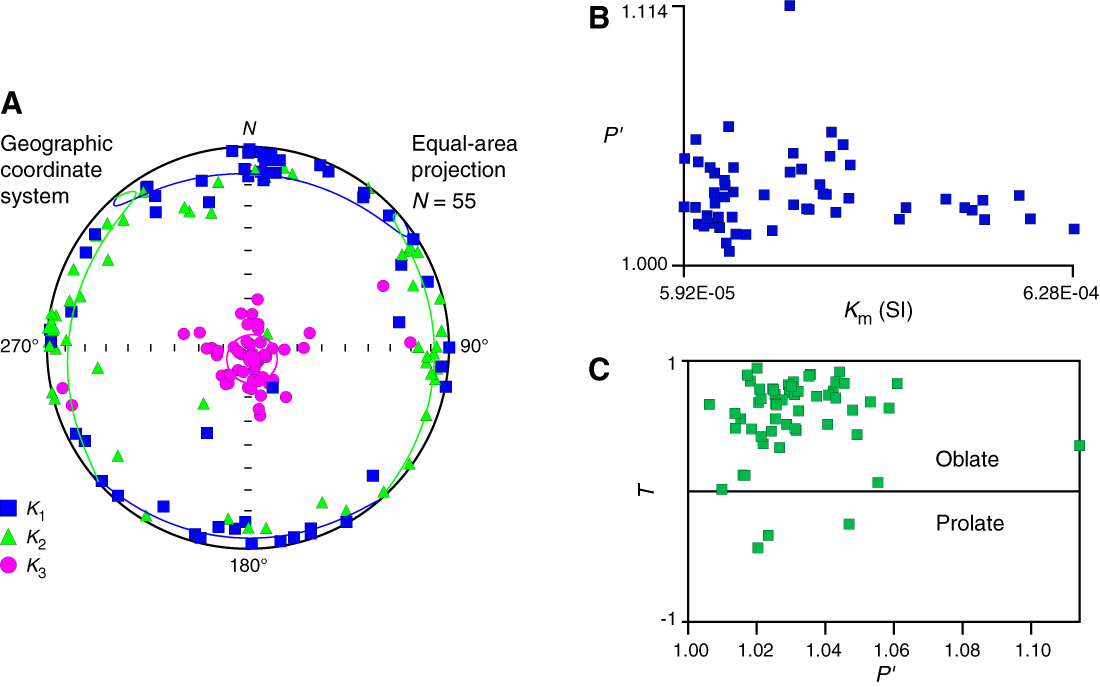
Figure F20. AMS data.
Geochemistry
Hydrocarbon gases were detected in deeper sediments only at Site U1505 and not at shallow depths. Thus, the base of the hole has methane distributions similar to those at Site U1499 (which has methane at depth), whereas the uppermost section is similar to Site U1501, which is barren of methane. Except for the shallowest 30 m of sediment, TOC, TN, and TS contents were mostly low in shallower lithostratigraphic Unit I, but TS and TOC were slightly higher in Unit II. Thus, in terms of solid organic geochemistry, Sites U1505 and U1501 are similar. Instances of high carbonate content are associated with bioclastic oozes. Interstitial water chemistry has two important features. The upper part exhibits patterns similar to those at Site U1501 in several respects (e.g., inhibited sulfate reduction), and there is evidence of freshwater input in deeper sediments (based on low chlorine, bromide, and salinity). Inductively coupled plasma–atomic emission spectroscopy analysis was not performed on samples collected at Site U1505.
Headspace gas
Headspace gas samples were taken at a frequency of one sample per core or per 10 m of drilling advance for routine safety monitoring. As at Site U1501, methane was not abundant in shallow sediments at Site U1505 (uppermost 50 m), although it was detected deeper in the hole at ~150 and ~ 400 m. Concentrations range from 70 to 3899 ppmv from 380 to 438 m, with a single instance of ethane found at this depth. A small concentration of methane was also detected at 150 m.
Bulk sediment geochemistry
Solid geochemistry parameters are listed in Table T10.
Table T10. Carbon, nitrogen, and sulfur. View table in PDF format. Download table in CSV format.
Lithostratigraphic Unit I
As seen at Site U1501, the uppermost black mud (lithostratigraphic Subunit IA) has relatively high TOC and TN contents relative to the units beneath. Sulfur content, although low in this unit, is higher than in the subunits immediately beneath it (Figure F21). Lithostratigraphic Subunits IB and IC have generally low TOC (<1 wt%) and low TS, which is also the case for Site U1501, where organic carbon is also least well preserved in these units.
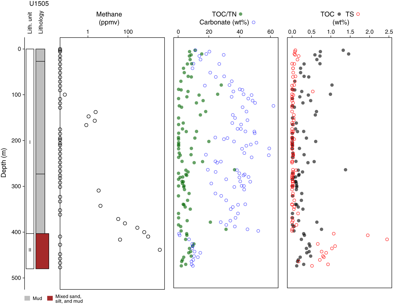
Figure F21. Carbon, nitrogen, and sulfur.
Lithostratigraphic Unit II
Lithostratigraphic Unit II has high sulfur and low carbonate content, and relative to Subunits IB and IC, it has significant organic carbon content (typically 0.5 wt%). The TOC/TN ratio for the interval is low, indicating high-nitrogen material, which would classically be interpreted as well-preserved organic matter of aquatic origin (Hedges et al., 1988).
High carbonate contents were found in bioclast-rich Subunits IB and IC. On a crossplot, Subunit IA and Unit II both have distinctively low carbonate contents and low TOC/TN ratios (Figure F22), indicating a high proportion of aquatic organic matter, and Subunits IB and IC appear to have organic matter that has been more heavily degraded or is terrestrial in origin (Hedges et al., 1988). On a carbon-sulfur crossplot, the distinctively high sulfur content in Unit II is a little unusual because it does not have much organic matter. The unit appears to have a high abundance of reduced sulfur, whereas Subunit IA has low sulfide content, given that it is relatively organic carbon–rich marine mud (Berner and Raiswell, 1984).
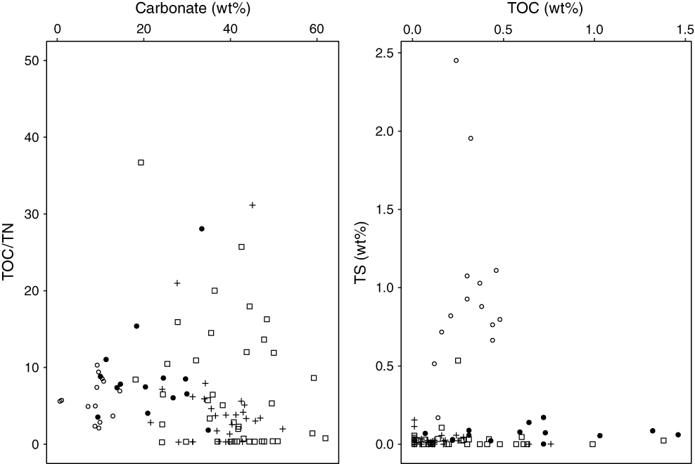
Figure F22. Organic geochemical parameters.
Raman and surface-enhanced Raman spectroscopy
Surface-enhanced Raman measurements were performed on shallow core and mudline samples from Holes U1505A–U1505D. Concentrations are reported as nanograms asphaltene per gram of sediment in Figure F23.
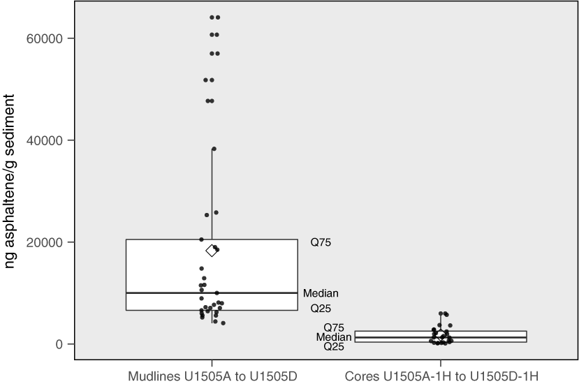
Figure F23. Asphaltene concentrations.
Interstitial water chemistry
Shipboard analyses were performed on interstitial water squeezed from 5–20 cm long whole-round sediment samples from Hole U1505C. From Cores 1H through 46F, 5–15 cm long intervals were squeezed for interstitial water and yielded >30 mL per sample. From Cores 46F through 64X, 20 cm long whole-round sediment cores were squeezed and yielded 5–20 mL of interstitial water. Interstitial water geochemical parameters are presented in Table T11 and Figure F24.
Table T11. Interstitial water analyses. View table in PDF format. Download table in CSV format.
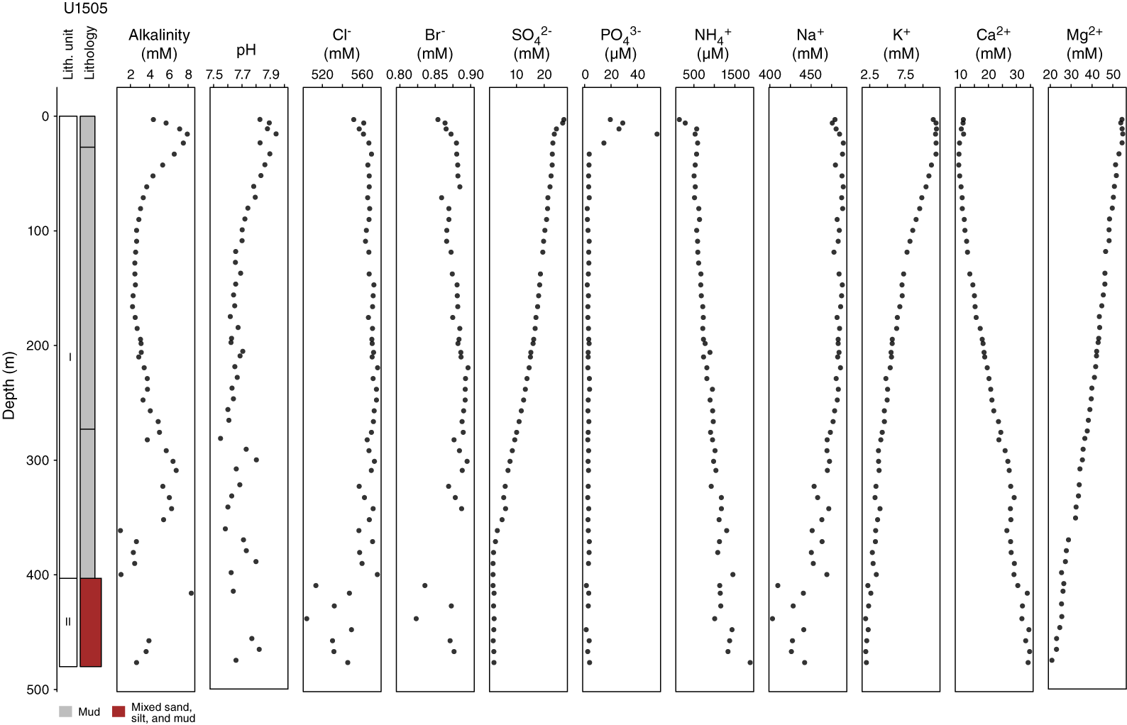
Figure F24. Interstitial water alkalinity, major cations, and anions.
In general, the geochemical parameters of interstitial water at Site U1505 are similar to those at Site U1501. We also defined three geochemical interstitial water zones at Site U1505 based on the variations of geochemical parameters (listed in Table T11). Interstitial water Zone 1 (interval 368-U1505C-1H-2, 0–5 cm, to 3H-4, 0–10 cm) comprises samples obtained close to the mudline (sediment/water interface). Within this interval, the maximum values of sulfate, alkalinity, and phosphate were observed and are likely related to degradation of organic matter. In interstitial water Zone 2 (interval 4H-4, 0–10 cm, to 56X-4, 0–20 cm), sulfate decreases and alkalinity is buffered by high carbonate concentrations within foraminifer-rich oozes. Atypically for this marine setting (Li et al., 2015), in which sulfate reduction is prevalent in marine sediments, diffusion processes dominate the sulfate profile. Decreasing K and Mg and increasing Ca reflect the typical diffusion-formed profile of interstitial water. In interstitial water Zone 3 (interval 57X-4, 0–20 cm, to 64X-4, 0–20 cm), sodium, chloride, and bromide concentrations are anomalously low.
Alkalinity varies within Hole U1505C, ranging from 1.0 to 8.3 mM (Figure F24). In interstitial water Zone 1, alkalinity increases to a peak concentration of 7.9 mM at 15.65 m (Sample 2H-5, 0–5 cm). The change in alkalinity is most likely caused by degradation of organic matter. In interstitial water Zone 2, alkalinity decreases to <3 mM at 90 m and remains constant until 185 m. Alkalinity increases again to a peak concentration of 6.8 mM at 308 m and then decreases downhole to the base of interstitial water Zone 2. The pH value decreases slowly from the seafloor to the bottom of interstitial water Zone 2 and then increases to a maximum (pH = 7.82) at the bottom of interstitial water Zone 3 (Sample 63X-4, 0–20 cm).
Profiles of Cl, Br, and Na are similar (Figure F24). In interstitial water Zone 1, Cl, Br, and Na concentrations increase slightly with depth. In interstitial water Zone 2, Cl, Br, and Na remain constant to 322 m (Sample 48X-4, 0–20 cm) with concentrations similar to seawater, and then between 322 and 400 m, Cl and Na concentrations vary. Interstitial water Zone 3 has low Cl, Br, and Na concentrations that decrease to a minimum in interstitial water Zone 3. A similar phenomenon was also observed in Hole U1501C, although the depth at which it occurs is different. In both cases, this minimum corresponds to the stratigraphic level of the T60 seismic unconformity. This correlation is discussed in detail later.
The dissolved sulfate profile decreases from 27.1 mM at the seafloor to <2 mM at the bottom of Hole U1505C (Figure F24). In interstitial water Zone 1, sulfate concentrations decrease sharply, most likely caused by bacterially mediated organic matter diagenesis in upper sediments. In interstitial water Zone 2, this decline is gradual until near-minimum concentrations are observed. In interstitial water Zone 3, sulfate concentrations are low.
Dissolved NH4+ concentrations increase from 143.6 μM at 2.96 m to a maximum of 1874 μM at the bottom of Hole U1505C. In interstitial water Zone 1, a sharp increase in NH4+ was observed that would typically be explained by degradation of organic matter releasing reduced nitrogen. In interstitial water Zones 2 to 3, continuous increases in NH4+ concentration suggest the existence of a source of NH4+ that diffuses upward from the bottom. A maximum dissolved phosphate concentration was observed in interstitial water Zone 1 (54.85 μM at 15.65 m). In interstitial water Zones 2–3, phosphate concentrations are generally low (several micromolar concentration).
The K+ and Mg2+ profiles decrease in a similar way to each other from the surface to the bottom of the hole. The decreases of K and Mg are possibly due to diagenetic reactions occurring in sediment, such as clay ion exchange. Contrary to the K and Mg pore water profiles, the Ca2+ profile increases from the surface to a maximum concentration (33.5 mM) at the bottom of Hole U1505C. Changes in calcium concentration are mostly caused by carbonate diagenesis (i.e., dissolution of biogenic carbonate and recrystallization of authigenic carbonates).
Discussion
Sulfate–methane transition zones
Figure F25 illustrates geochemical parameters that help explain the shallow biogeochemical processes occurring in SCS sediments. The sulfate–methane transition zone (SMTZ) occurs where organic matter degradation consumes dissolved substrates (foremost oxygen and then others such as phosphate, ammonium, etc.) and anaerobic conditions develop (Barnes and Goldberg, 1976). The SMTZ can be defined by the depletion of sulfate within pore water and the beginning of methanogenesis (elevated methane concentrations within sediments). Site U1499 has an SMTZ at ~70 m that likely reflects present-day processes. Site U1505 has a possible SMTZ at ~400 m, but it is not sharply defined (e.g., sulfate does not sharply inflect at this depth).
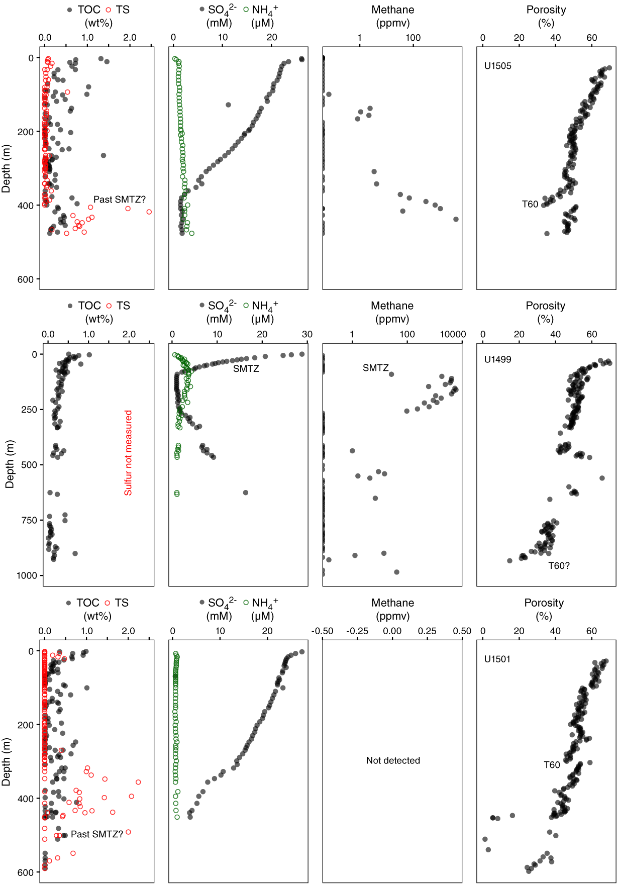
Figure F25. Comparison of SMTZs and key biogeochemical elements.
Both sedimentation rate and the presence of organic matter are important for the development of an SMTZ. TOC contents are essentially comparable between the three sites, with Site U1499 perhaps having a lower TOC because of a high input of sediment (sediment dilutes the organic carbon content). Despite the low absolute TOC, the net accumulation rate per unit time may still be comparable for all three sites. Thus, differing supply of organic carbon is not likely to be a key factor, with differences in sedimentation rate being the more likely differentiator between sites. High sedimentation rates promote anaerobic conditions by more rapidly burying organic matter to depths below which oxygen can diffuse (Demaison and Moore, 1980).
Evidence of past SMTZs can be preserved in a number of ways: high methane concentrations may remain in hydrostatic waters and reduced sulfur (sulfide) may mineralize in the form of sulfide minerals such as pyrite or greigite. Thus, a past SMTZ may be preserved beneath the T60 unconformity at Site U1505 where low pore water sulfate, high methane, and high TS are observed. Seepage from this zone at 400 m may also thus explain the methane present at shallower depths. The three sites together form an interesting study potentially demonstrating that the T60 unconformity surface is an important boundary affecting biogeochemical processes by controlling the flux of deeper fluids to shallower sediments.
Sub-T60 unconformity halide formation water anomaly
Important anions for understanding the formation water anomaly in chloride and bromide beneath the T60 unconformity are shown in Figure F26. Any such explanation must take account of the conservative nature of the halide ions—they are not generated from diagenetic reactions typical of marine sediments. Any explanation must also allow for the linear changes in depth (reflecting temperature) observed in the major cations such as magnesium, calcium, and potassium.

Figure F26. Halide interstitial water anomaly.
Two possible explanations for the sub-T60 unconformity halide anomaly are postdepositional recharge under a hydrodynamic regime or trapping of an original fresher water body depleted in these ions. The salinities and halide concentrations observed are low for marine water but toward the high end of brackish water. Such a water body might have been deposited with the sediment or potentially moved into the sediment very early in its history through subtidal pumping (Shum and Sundby, 1996), albeit only during storm events for deeper water sediments. The origin of the bromide, chloride, and sodium anomaly can best be explained by a trapped water body depleted in these anions and subsequent alteration of calcium, magnesium, and potassium in pore waters during diagenesis. Were the current water hydrodynamically emplaced after deposition, it would have to contain exactly the correct proportions of calcium, magnesium, and potassium to not disturb the depth-dependent trend.
Instead, it is more feasible that subsequent diagenetic processes such as smectite-illite transformation (Boles and Franks, 1979) or cation exchange involving carbonate minerals, which are temperature dependent (depth dependent), has released or taken up calcium, magnesium, and potassium from pore waters and thereby altered a trapped water body. A trapped water body would not be able to acquire a new halide-anion composition but would be able to equilibrate during diagenesis and produce the linear increase with depth seen here in calcium, magnesium, and potassium. Such a trapped water body might also cause a formation to be lithostatically pressured and hence undercompacted, leading to the higher porosities observed in the sub-T60 unconformity lithologies (Bethke, 1986).
Physical properties
Whole-round measurements of magnetic susceptibility, gamma ray attenuation (GRA) bulk density, P-wave velocity (P-wave logger [PWL]), and NGR were made on each core recovered from Holes U1505C (0–480.2 m) and U1505D (0–184 m). Only nondestructive measurements were performed on the cores from Hole U1505D, which is a duplicate of Hole U1505C downcore to 184 m. P-wave velocity was also measured on working-half sections using the P-wave caliper (PWC) system. Thermal conductivity was measured on one section, typically Section 3, for each core. Additionally, discrete samples from Hole U1505C were analyzed for bulk density, porosity, and dry and grain density. Color reflectance, RGB color spectra, and point magnetic susceptibility were measured on all archive-half sections from Holes U1505C and U1505D.
Because the cores recovered from Hole U1505D sampled the same lithologic section as in the uppermost ~180 m in Hole U1505C, the discussion here will focus on Hole U1505C. Based on the physical property characteristics, the lithologic sequence recovered from Hole U1505C was divided into two petrophysical (PP) units, PP Units 1 and 2, with a boundary at 403 m (Figure F27). This boundary corresponds to the boundary between lithostratigraphic Units I and II. The interface between these two units is marked by an abrupt shift in physical property measurements. The entire sequence recovered from Hole U1505D was assigned to PP Unit 1 (Figure F28). Hole U150C cores show some drilling disturbance deeper than ~250 m (see Lithostratigraphy).
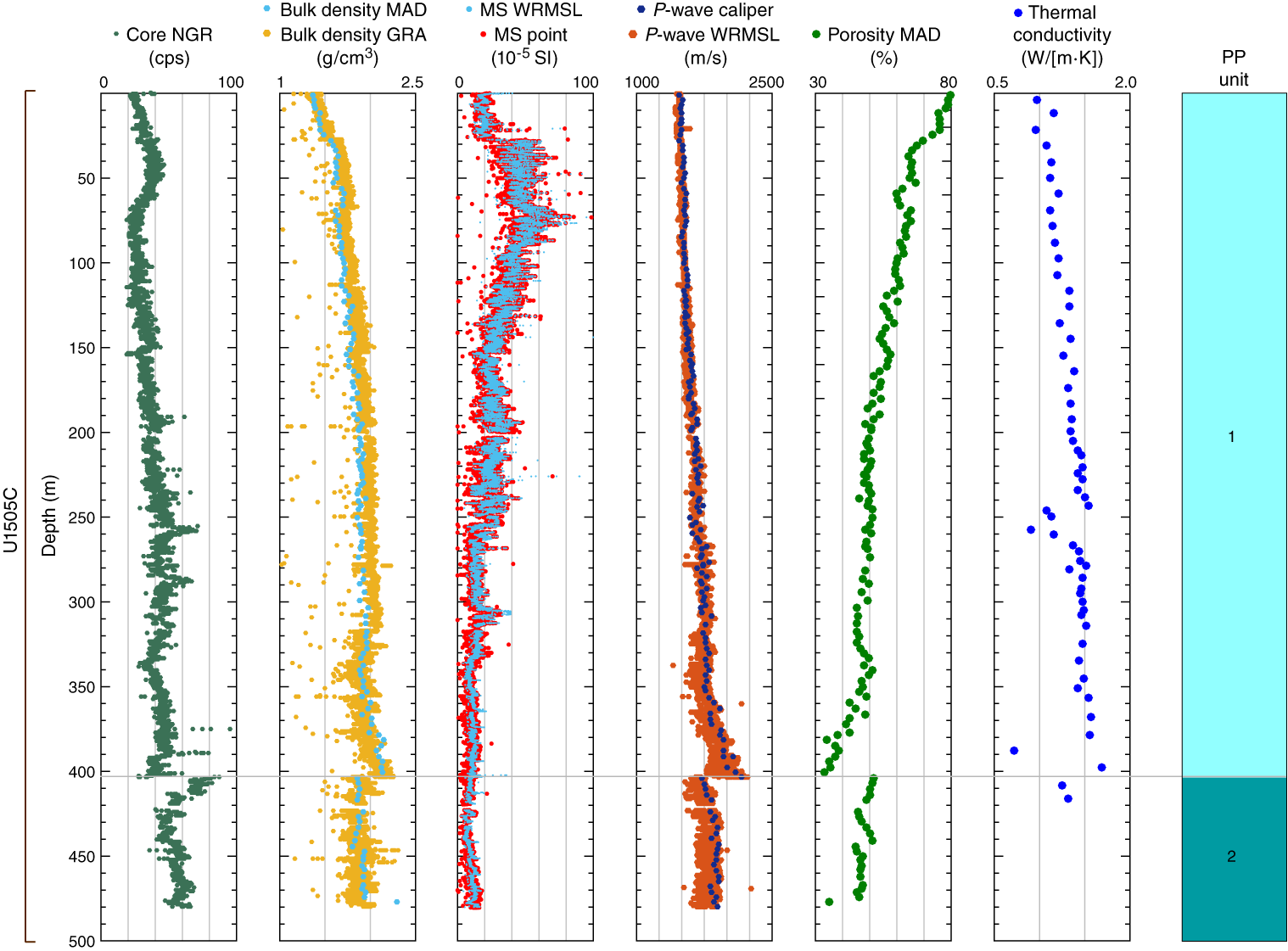
Figure F27. Physical properties, Hole U1505C.
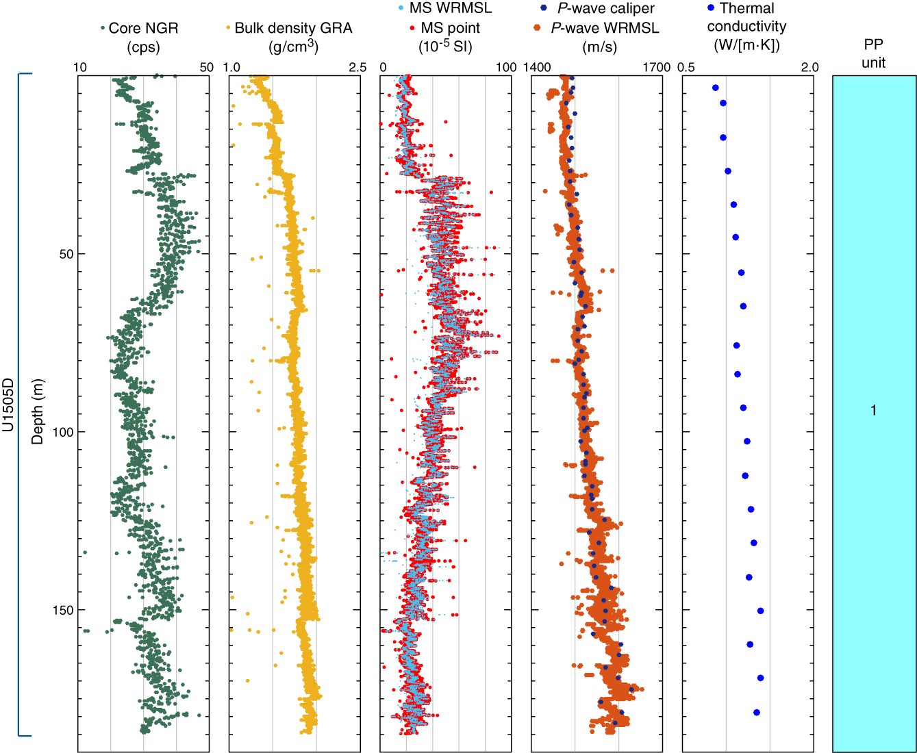
Figure F28. Physical properties, Hole U1505D.
Natural gamma radiation
NGR values in PP Unit 1 are represented by three major intervals (Figure F27). The upper interval from the seafloor to ~65 m ranges from ~20 to ~45 counts/s, and NGR values peak around the middle of this depth range. The second interval (~65–~335 m) is also marked by initially increasing NGR between ~20 and ~55 counts/s. NGR values then gradually decrease at the bottom of this interval to 35 counts/s at ~335 m. The lowermost interval of PP Unit 1 displays a general increase in NGR. This interval ends with an abrupt decrease in NGR to 35 counts/s close to 403 m, followed by a sharp increase to ~75 counts/s at ~403 m associated with the top of PP Unit 2. In PP Unit 2, NGR decreases to ~45 counts/s at 440 m and then increases.
P-wave velocity
In PP Unit 1, P-wave velocity values gradually increase with depth from ~1470 m/s at the seafloor to ~1765 m/s at ~335 m, followed by an increase that reaches ~2166 m/s at ~403 m (Figure F27). P-wave velocity values decrease sharply at the PP Unit 1/2 boundary to 1725 m/s and then remain relatively constant at ~2000 m/s from this point downhole to ~480 m.
Thermal conductivity
Thermal conductivity values show a well-defined trend in the designated petrophysical units. PP Unit 1 has a gradual increasing trend with depth. In this unit, thermal conductivity ranges from 0.906 to 1.684 W/(m·K) (Figure F27). The trend is interrupted with scattered values at ~250–270 m. This scatter could be due to drilling disturbance. PP Unit 2 shows a sudden drop in thermal conductivity with values ranging from 1.248 to 1.314 W/(m·K). In PP Unit 2, more measurements could not be done due to the high drilling disturbance in the cores.
Density and porosity
In PP Unit 1 (0–403 m), bulk density increases with depth from 1.4 g/cm3 at the seafloor to ~2.1 g/cm3 at the base of the unit (Figures F27, F29). Porosity shows an inverse trend to density and decreases from ~80% to ~35%. Grain density varies between 2.7 and 2.8 g/cm3 with no visible downcore trend (Figure F29). The interface between PP Units 1 and 2 (~403 m) is marked by an abrupt decrease in bulk density from 2.1 to 1.9 g/cm3 and dry density from 1.8 to 1.3 g/cm3. In contrast, porosity increases dramatically across this depth interval from ~34% to ~52%. This boundary coincides with the T60 seismic unconformity (see Correlation to seismic data) and can also be clearly recognized in other physical property data, including NGR, P-wave velocity, and color data (Figures F27, F29, F30, F31). In PP Unit 2 (403–480.2 m), bulk density increases slightly with depth from 1.86 to >1.96 g/cm3 and dry density increases from ~1.3 to ~1.5 g/cm3. Porosity decreases with depth from 51% to 35%.

Figure F29. Density and porosity.
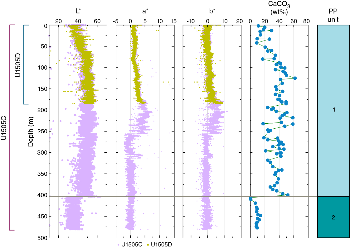
Figure F30. Sediment color reflectance.
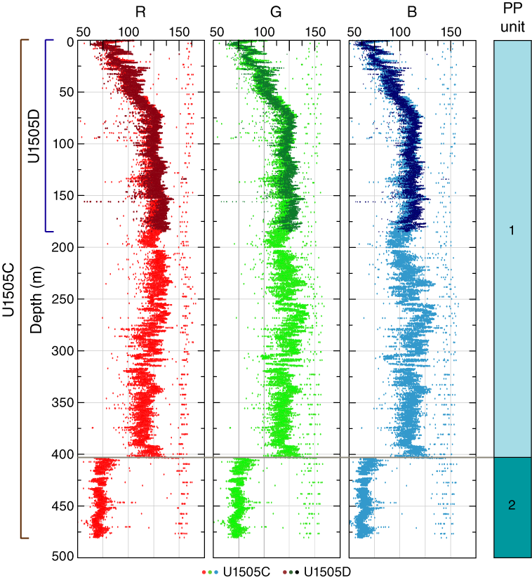
Figure F31. RGB values.
Color reflectance spectrophotometry
Sediment color reflectance values are in very good agreement between Holes U1505C and U1505D, as expected (Figure F30). L* represents luminosity, or total reflected light, and is well correlated to CaCO3 content in sediments (see Geochemistry). In PP Unit 1, L* overall increases with depth from the seafloor to ~75 m; thereafter, downhole L* values fluctuate between 50 and 60 but overall remain relatively constant to ~400 m, where they drop to <40 in PP Unit 2.
Reflectance a* and b* values indicate redness and yellowness of sediments, respectively, and show consistent variations with core depth (Figure F30). In PP Unit 1, both a* and b* gently increase in the upper portion (0 to ~180 m), followed by a section with high-amplitude variability between ~200 and 260 m, before they drop to minimum and relatively constant values to the base of the record. No significant shift in a* and b* was observed at the unit boundary.
Magnetic susceptibility
Whole-round magnetic susceptibility and point magnetic susceptibility values show a good, consistent trend throughout all core sections from Holes U1505C and U1505D (Figures F27, F28). In PP Unit 1, the magnetic susceptibility profile can be viewed as three windows of different trends: (1) low and constant magnetic susceptibility from 0 to 30 m with a mean value of ~20 × 10−5 SI, (2) high and constant magnetic susceptibility from 30 to 80 m with a mean value of ~45 × 10−5 SI, and (3) gradually decreasing magnetic susceptibility from 80 to 403 m. In PP Unit 1, the trend is frequently interrupted by spikes downcore. Finally, PP Unit 2 is associated with a persistently low and constant magnetic susceptibility of ~5.
RGB
RGB in PP Unit 1 steadily increases with depth from the seafloor to 70 m, reaching a maximum of 130 followed by constant values until the bottom of PP Unit 1 (Figure F31). At 403 m, corresponding to the boundary between PP Units 1 and 2, RGB values show a marked decrease (from 110 to 75). Below this depth, RGB remains relatively constant to the bottom of PP Unit 2.
Discussion and summary
The observed physical properties allow us to characterize two major petrophysical units at Site U1505. The sediments recovered display a distinct color change from greenish and brownish light gray to greenish dark gray at 403 m (see Lithostratigraphy). This boundary, which represents the seismic stratigraphic T60 unconformity, is associated with a sharp change in physical properties.
PP Unit 1 shows overall gradually increasing NGR, bulk density, P-wave velocity, and thermal conductivity and decreasing magnetic susceptibility and porosity (Figures F27, F28). In contrast, PP Unit 2 (403–480 m) is characterized by a sharp change in physical properties at its upper boundary (403 m) but a relatively constant trend downhole within the unit.
In PP Unit 1 (0–403 m), sediments are composed of foraminifer-rich nannofossil ooze with clay in the upper part, which gradually changes to clay-rich nannofossil ooze in the lower portion of the unit. This transition is well reflected in NGR, which increases with depth. The higher NGR in PP Unit 2 is related to sediment that primarily consists of silty clay (Figures F27, F28). The NGR and magnetic susceptibility trends have frequent spikes.
Density, porosity, and P-wave velocity suggest compaction is a major factor responsible for the observed downhole trend in PP Unit 1. Sediments in PP Unit 1 show porosity values similar to those recorded at nearby Site U1501 at a similar depth interval, suggesting the same compaction history. In PP Unit 2, density and P-wave velocity decrease abruptly at the boundary and then increase relatively constantly downhole, whereas porosity shows the opposite trend (Figures F27, F29). Thermal conductivity overall increases with depth. The higher magnetic susceptibility values in the upper portion of PP Unit 1 could be due to higher concentrations of magnetic materials like magnetite.
In the PP units, reflectance L* and RGB channels show similar trends that are well correlated with the percent carbonate trend. The higher L* and RGB values reflect higher carbonate contents. Lower values in L* and RGB correspond to the dark gray sediments in PP Unit 2 (Figures F30, F31).
Downhole measurements
Logging operations
After coring to 480.3 m in Hole U1505C, a wiper trip was made to verify hole conditions and allow debris collected around the drill collars to fall into the bottom of the hole. After the last core, the rotary core barrel (RCB) drill bit was released at the bottom of the hole. The drill pipe was raised to 78 m prior to logging (Figure F32). Rig-up for downhole logging started at 0930 h (local time; UTC + 8 h) on 2 June 2017. The modified triple combo tool string started downhole at 1130 h on 2 June. The uphole pass of the triple combo run began at 1350 h. After completing two down- and uphole passes, the tool string reached the seafloor at 1550 h, and the logging tools were rigged down at 1910 h. The wireline active heave compensator (AHC) was used throughout the logging operations. Because the drill hole diameter for most of the logging depth was greater than 14–16 inches, it was decided not to run a second logging run with the FMS tool string.
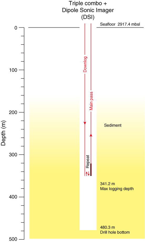
Figure F32. Logging operations summary.
The modified triple combo tool string included the HNGS, HLDS, HRLA, MSS, and DSI (Figure F33). The tool string encountered difficulty going down at approximately 341.2 m, where several attempts to pass that depth failed; thus, the logging depth was 341.2 m.
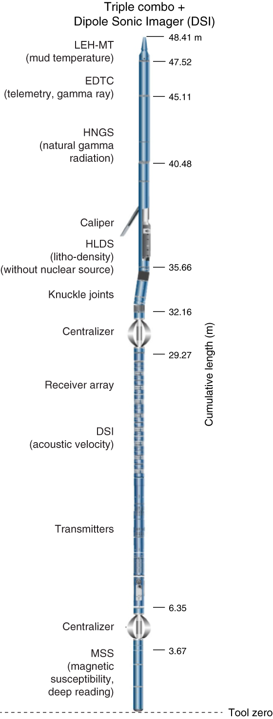
Figure F33. Triple combo tool string.
Logging units
The triple combo run in Hole U1505C allowed us to define six logging units that are correlated with hole conditions, lithostratigraphic units, lithology, and physical properties (Figure F34).
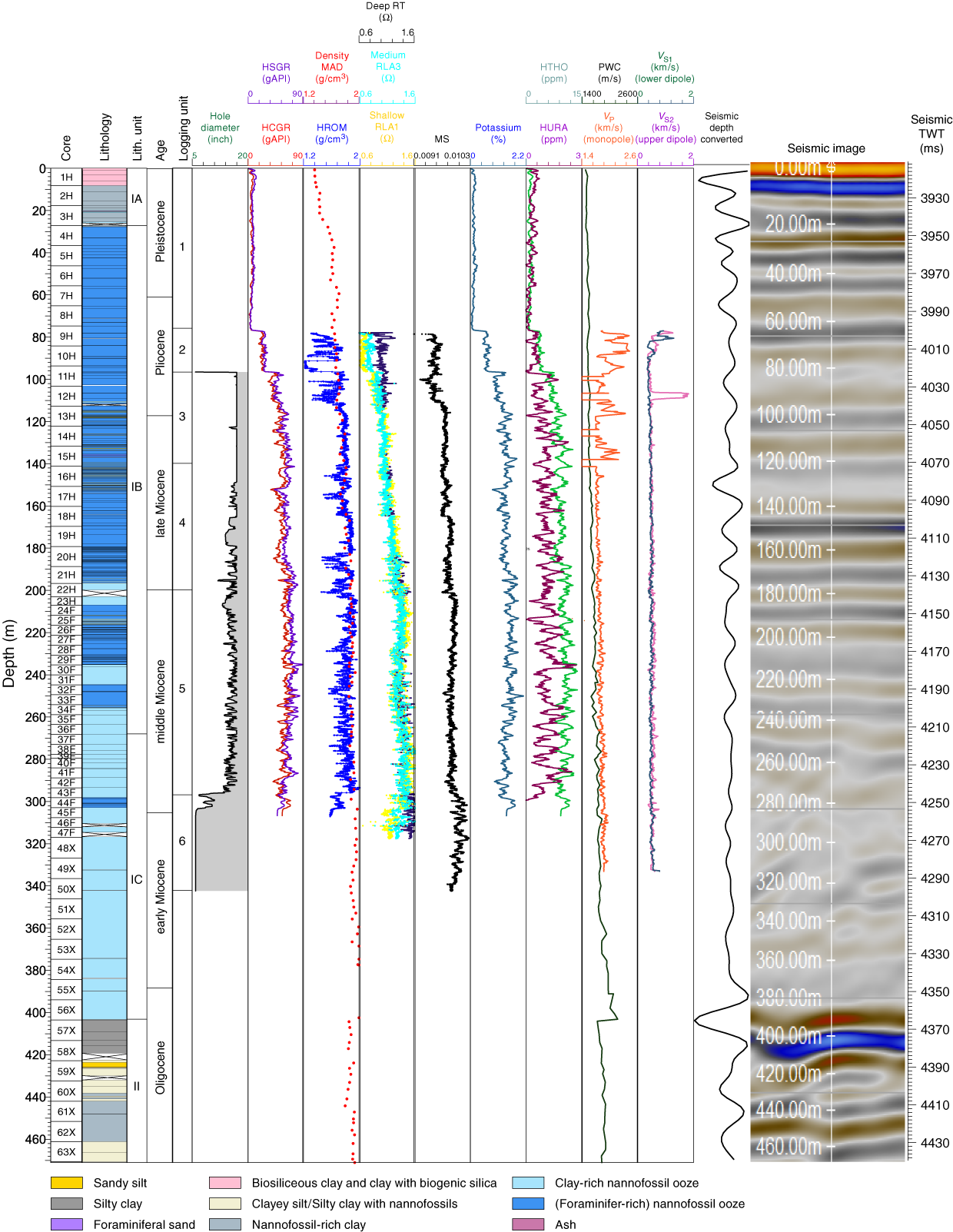
Figure F34. Downhole logs.
Logging Unit 1: seafloor to base of drill pipe
Logging Unit 1 extends from the seafloor to the base of the drill pipe at 78 m. The natural gamma ray (total spectral gamma ray [HSGR] and computed gamma ray [HCGR]) is highly attenuated inside the drill pipe. The potassium, thorium, and radium components of the natural gamma ray are also attenuated.
Logging Units 2 and 3: base of drill pipe to 136 m
Logging Unit 2 is from the base of the drill pipe to 96 m. The drill hole diameter is unknown for this unit. The natural gamma ray (HSGR and HCGR) of this unit is about 50% of the values of the formation below. The logging density (high-resolution corrected bulk density) is low at 90–96 m, which might reflect a relatively large hole diameter.
Logging Unit 3 is at 96–136 m. The drill hole diameter reached the maximum caliper width of 18 inches for most of this unit. The natural gamma ray increases with depth. The logging compressional wave velocity (VP) exhibits large fluctuations that could be due to the enlarged hole dimensions. The shear wave velocity (VS) shows an anomalous value at 104–110 m for an unknown reason. Logging Units 2 and 3 both correspond to a section of lithostratigraphic Subunit IB (Figure F34; see Lithostratigraphy).
Logging Units 4–6: 136–341.2 m
Logging Unit 4 is at 136–220 m. The upper portion of this unit has a relatively large hole diameter. Both VP and VS are relatively constant. This logging unit corresponds to a section of lithostratigraphic Subunit IB (Figure F34; see Lithostratigraphy).
Logging Unit 5 is at 200–296 m. The drill hole diameter is close to 14–16 inches for this logging unit. Resistivity increases with depth, whereas most of the other physical properties remain relatively constant. This logging unit corresponds to the bottom of lithostratigraphic Subunit IB and the top of Subunit IC (Figure F34; see Lithostratigraphy).
Logging Unit 6 is at 296–341.2 m. The drill hole diameter is relatively smaller for this unit. Magnetic susceptibility for this unit is greater than that of logging Unit 5. Logging Unit 6 corresponds to the lower part of lithostratigraphic Subunit IC (Figure F34; see Lithostratigraphy). Where the logging velocity has relatively good quality (~141.5–333.0 m), the logging VP is systematically greater than the P-wave velocity measured by caliper (PWC) on the working halves of the core sections.
Downhole temperature and heat flow
Four downhole temperature measurements were conducted at Hole U1505C using the APCT-3. The temperature values range from 4.7°C at 36.7 m to 11.7°C at 122.8 m, giving a geothermal gradient of 84.6°C/km (Figure F35A). These values, together with the seafloor temperature of 1.4°C, indicate that the temperature increases linearly with depth.
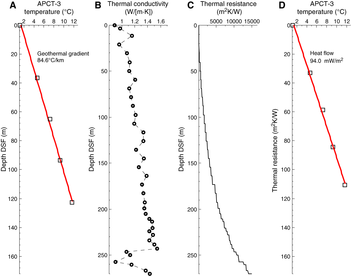
Figure F35. Heat flow calculations.
Thermal conductivity under in situ conditions was estimated from laboratory-determined thermal conductivity from Hole U1505C using the method of Hyndman et al. (1974) (see Physical properties in the Expedition 367/368 methods chapter [Sun et al., 2018]). Thermal resistance (Figure F35C) was then calculated by integrating the inverse of the in situ thermal conductivity over depth (Figure F35B). A heat flow of 94.0 mW/m2 was obtained from the linear fit between temperature and thermal resistance (Figure F35D) (Pribnow et al., 2000). The geothermal gradient and heat flow at Site U1505 are comparable to the relatively high values observed at a number of ODP, Integrated Ocean Drilling Program, and IODP sites in this part of the SCS, including Sites U1432 (100.1 mW/m2), U1499 (114 mW/m2, this volume), and U1501 (100.2 mW/m2, this volume).
Correlation to seismic data
We conducted two sets of analyses to correlate the core measurements (in meters below seafloor) to the time-based seismic data at Site U1505. First, we analyzed core data and investigated correlation to the seismic reflection profile. Second, we constructed synthetic seismograms using Site U1505 core data and compared the results with the traces in the seismic profile. Preliminary calculations were done during the expedition using a combination of Matlab scripts and Petrel software.
Velocity and density data and comparison with seismic reflectors
Whole-round core measurements were conducted from the seafloor to 480.3 m in Hole U1505C (Figure F36) and from the seafloor to 185 m in Hole U1505D. P-wave velocity was also measured along the x-axis with the PWC system on working-half sections. MAD measurements were performed on discrete samples, one every other section. In addition, HLDS density, VP, and VS measurements were obtained from downhole logging in Hole U1505C at 78–341.2 m (see Physical properties and Downhole measurements). With the outliers filtered out, the whole-round PWL velocity and GRA density data show a good match with the PWC velocity and MAD density of core samples, respectively (Figure F36). However, the logging VP is systematically greater than PWC for depth intervals of good logging velocity data quality (Figure F37; see Downhole measurements).

Figure F36. Physical property comparison.
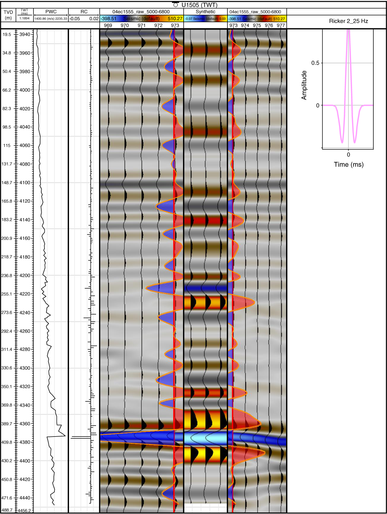
Figure F37. Synthetic seismogram.
A major change in VP and density was identified at ~403 m, coinciding with the lithologic change from nannofossil ooze–dominated sediments to silt and clay–dominated sediments (Figure F36; see Lithostratigraphy). We hypothesized that the strong negative reflection (4374 ms two-way traveltime [TWT]) at Site U1505 corresponds to the basin-wide T60 seismic unconformity (reference Point 1; Figures F36, F38).
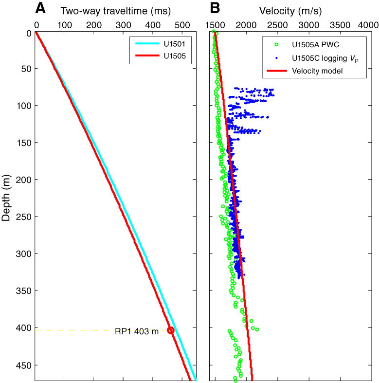
Figure F38. TDR curve comparison.
Time-depth relationship
A time-depth relationship (TDR) model for Site U1505 was calculated using a polynomial function (Figure F38A):
where d is depth in meters below seafloor and t is TWT in milliseconds.
We correlated a strong reflector (reference Point RP1; 4374 ms TWT) to a major change in VP and density at ~403 m (Figure F36). This calculated TDR function yields an interval velocity that increases with depth (red line in Figure F38B). Where the logging velocity values (blue dots in figure) are relatively good quality (~141.5–333.0 m), they are systematically greater than the PWC core values (green dots) by as much as ~200 m/s. The calculated interval velocity from the TDR model (red line in figure) is much closer to the observed logging VP than the PWC values.
Using the best-fitting TDR model for Site U1505 (red line in Figure F38A), we were able to convert “depth scale” to “timescale” for all core measurements. This conversion enabled us to display the core measurements directly on top of the time-based seismic sections, facilitating identification of correlated features, as illustrated in Figure F39.
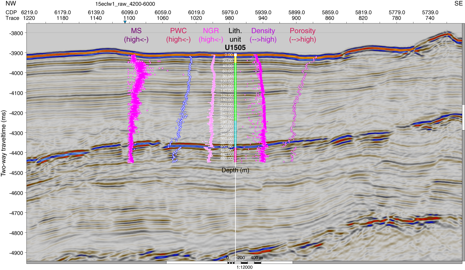
Figure F39. Seismic section with overlaid lithostratigraphic units.
Synthetic seismograms
To further illustrate the relationship between the core measurements at Site U1505 and the seismic reflection profile, the “Seismic interpretation” module in Petrel was used to compute synthetic seismograms based on the relevant core measurements (Figure F37). Synthetic traces were generated by convolving the reflectivity from the density of core samples, an interval velocity model, and with the source wavelet that best fits the seismic data (“Ricker 2”; Figure F37).
Seismic impedance (SI) of a rock layer is the product of its average seismic velocity (VP) and density (ρ) (i.e., SI = VP × ρ). The seismic reflection coefficient, in turn, equals the change in seismic impedance between two adjacent rock layers. Thus, we can expect greater amplitudes in the modeled seismogram for rock interfaces with larger values of reflection coefficient. The resulting synthetic seismogram shows a strong “negative” phase reflector at ~400–405 m, consistent with the observed depth of a strong seismic reflector (Figure F37).
References
Barnes, R.O., and Goldberg, E.D., 1976. Methane production and consumption in anoxic marine sediments. Geology, 4(5):297–300. https://doi.org/10.1130/0091-7613(1976)4<297:MPACIA>2.0.CO;2
Berner, R.A., and Raiswell, R., 1984. C/S method for distinguishing freshwater from marine sedimentary rocks. Geology, 12(6):365–368. https://doi.org/10.1130/0091-7613(1984)12<365:CMFDFF>2.0.CO;2
Bethke, C.M., 1986. Inverse hydrologic analysis of the distribution and origin of Gulf Coast-type geopressured zones. Journal of Geophysical Research: Solid Earth, 91(B6):6535–6545. https://doi.org/10.1029/JB091iB06p06535
Blow, W.H., 1969. Late middle Eocene to recent planktonic foraminiferal biostratigraphy. Proceedings of the International Conference on Planktonic Microfossils, 1:199–422.
Boles, J.R., and Franks, S.G., 1979. Clay diagenesis in Wilcox sandstones of southwest Texas: implications of smectite diagenesis on sandstone cementation. Journal of Sedimentary Petrology, 49(1):55–70. https://doi.org/10.1306/212F76BC-2B24-11D7-8648000102C1865D
Briais, A., Patriat, P., and Tapponnier, P., 1993. Updated interpretation of magnetic anomalies and seafloor spreading stages in the South China Sea: implications for the Tertiary tectonics of Southeast Asia. Journal of Geophysical Research: Solid Earth, 98(B4):6299–6328. https://doi.org/10.1029/92JB02280
Demaison, G.J., and Moore, G.T., 1980. Anoxic environments and oil source bed genesis. AAPG Bulletin, 64:1179–1209.
Drzewiecki, P.A., and Simó, J.A., 2002. Depositional processes, triggering mechanisms and sediment composition of carbonate gravity flow deposits: examples from the Late Cretaceous of the south-central Pyrenees, Spain. Sedimentary Geology, 146(1–2):155–189. https://doi.org/10.1016/S0037-0738(01)00171-3
Hedges, J.I., Clark, W.A., and Come, G.L., 1988. Organic matter sources to the water column and surficial sediments of a marine bay. Limnology and Oceanography, 33(5):1116–1136. https://doi.org/10.4319/lo.1988.33.5.1116
Hyndman, R.D., Erickson, A.J., and Von Herzen, R.P., 1974. Geothermal measurements on DSDP Leg 26. In Davies, T.A., Luyendyk, B.P., et al., Initial Reports of the Deep Sea Drilling Project, 26: Washington, DC (U.S. Govt. Printing Office), 451–463. https://doi.org/10.2973/dsdp.proc.26.113.1974
Kirschvink, J.L., 1980. The least-squares line and plane and the analysis of palaeomagnetic data. Geophysical Journal of the Royal Astronomical Society, 62(3):699–718. https://doi.org/10.1111/j.1365-246X.1980.tb02601.x
Larsen, H.C., Jian, Z., Alvarez Zarikian, C.A., Sun, Z., Stock, J.M., Klaus, A., Boaga, J., Bowden, S.A., Briais, A., Chen, Y., Cukur, D., Dadd, K.A., Ding, W., Dorais, M.J., Ferré, E.C., Ferreira, F., Furusawa, A., Gewecke, A.J., Hinojosa, J.L., Höfig, T.W., Hsiung, K.-H., Huang, B., Huang, E., Huang, X.-L., Jiang, S., Jin, H., Johnson, B.G., Kurzawski, R.M., Lei, C., Li, B., Li, L., Li, Y., Lin, J., Liu, C., Liu, C., Liu, Z., Luna, A., Lupi, C., McCarthy, A.J., Mohn, G., Ningthoujam, L.S., Nirrengarten, M., Osono, N., Peate, D.W., Persaud, P., Qui, N., Robinson, C.M., Satolli, S., Sauermilch, I., Schindlbeck, J.C., Skinner, S.M., Straub, S.M., Su, X., Tian, L., van der Zwan, F.M., Wan, S., Wu, H., Xiang, R., Yadav, R., Yi, L., Zhang, C., Zhang, J., Zhang, Y., Zhao, N., Zhong, G., and Zhong, L., 2018a. Site U1501. In Sun, Z., Jian, Z., Stock, J.M., Larsen, H.C., Klaus, A., Alvarez Zarikian, C.A., and the Expedition 367/368 Scientists, South China Sea Rifted Margin. Proceedings of the International Ocean Discovery Program, 367/368: College Station, TX (International Ocean Discovery Program). https://doi.org/10.14379/iodp.proc.367368.105.2018
Larsen, H.C., Jian, Z., Alvarez Zarikian, C.A., Sun, Z., Stock, J.M., Klaus, A., Boaga, J., Bowden, S.A., Briais, A., Chen, Y., Cukur, D., Dadd, K.A., Ding, W., Dorais, M.J., Ferré, E.C., Ferreira, F., Furusawa, A., Gewecke, A.J., Hinojosa, J.L., Höfig, T.W., Hsiung, K.-H., Huang, B., Huang, E., Huang, X.-L., Jiang, S., Jin, H., Johnson, B.G., Kurzawski, R.M., Lei, C., Li, B., Li, L., Li, Y., Lin, J., Liu, C., Liu, C., Liu, Z., Luna, A., Lupi, C., McCarthy, A.J., Mohn, G., Ningthoujam, L.S., Nirrengarten, M., Osono, N., Peate, D.W., Persaud, P., Qui, N., Robinson, C.M., Satolli, S., Sauermilch, I., Schindlbeck, J.C., Skinner, S.M., Straub, S.M., Su, X., Tian, L., van der Zwan, F.M., Wan, S., Wu, H., Xiang, R., Yadav, R., Yi, L., Zhang, C., Zhang, J., Zhang, Y., Zhao, N., Zhong, G., and Zhong, L., 2018b. Site U1503. In Sun, Z., Jian, Z., Stock, J.M., Larsen, H.C., Klaus, A., Alvarez Zarikian, C.A., and the Expedition 367/368 Scientists, South China Sea Rifted Margin. Proceedings of the International Ocean Discovery Program, 367/368: College Station, TX (International Ocean Discovery Program). https://doi.org/10.14379/iodp.proc.367368.107.2018
Li, C.-F., Lin, J., Kulhanek, D.K., Williams, T., Bao, R., Briais, A., Brown, E.A., Chen, Y., Clift, P.D., Colwell, F.S., Dadd, K.A., Ding, W., Hernández-Almeida, I., Huang, X.-L., Hyun, S., Jiang, T., Koppers, A.A.P., Li, Q., Liu, C., Liu, Q., Liu, Z., Nagai, R.H., Peleo-Alampay, A., Su, X., Sun, Z., Tejada, M.L.G., Trinh, H.S., Yeh, Y.-C., Zhang, C., Zhang, F., Zhang, G.-L., and Zhao, X., 2015. Expedition 349 summary. In Li, C.-F., Lin, J., Kulhanek, D.K., and the Expedition 349 Scientists, South China Sea Tectonics. Proceedings of the International Ocean Discovery Program, 349: College Station, TX (International Ocean Discovery Program). https://doi.org/10.14379/iodp.proc.349.101.2015
Lurcock, P.C., and Wilson, G.S., 2012. PuffinPlot: a versatile, user-friendly program for paleomagnetic analysis. Geochemistry, Geophysics, Geosystems, 13(6):Q06Z45. https://doi.org/10.1029/2012GC004098
Margielewski, W., Jankowski, L., Krapiec, M., Garecka, M., Hałas, S., and Urban, J., 2017. Analysis of reworked sediments as a basis of the Palaeogene-Neogene palaeogeography reinterpretation: case study of the Roztocze region (SE Poland). Sedimentary Geology, 352:14–29. https://doi.org/10.1016/j.sedgeo.2017.02.009
Martini, E., 1971. Standard Tertiary and Quaternary calcareous nannoplankton zonation. In Farinacci, A. (Ed.), Proceedings of the Second Planktonic Conference, Roma 1970: Rome (Edizioni Tecnoscienza), 2:739–785.
Ogg, J.G., Ogg, G., and Gradstein, F.M., 2016. A Concise Geologic Time Scale 2016: Boston (Elsevier).
Pribnow, D., Kinoshita, M., and Stein, C., 2000. Thermal Data Collection and Heat Flow Recalculations for Ocean Drilling Program Legs 101–180: Hanover, Germany (Institute for Joint Geoscientific Research, Institut für Geowissenschaftliche Gemeinschaftsaufgaben [GGA]). http://www-odp.tamu.edu/publications/heatflow/ODPReprt.pdf
Scherer, R.P., Gladenkov, A.Y., and Barron, J.A., 2007. Methods and applications of Cenozoic marine diatom biostratigraphy. In Starratt, S.W. (Ed.), Pond Scum to Carbon Sink: Geological and Environmental Applications of the Diatoms. Paleontological Society Papers, 13:61–83.
Shum, K.T., and Sundby, B., 1996. Organic matter processing in continental shelf sediments—the subtidal pump revisited. Marine Chemistry, 53(1–2):81–87. https://doi.org/10.1016/0304-4203(96)00014-X
Sun, Z., Jian, Z., Stock, J.M., Larsen, H.C., Klaus, A., Alvarez Zarikian, C.A., Boaga, J., Bowden, S.A., Briais, A., Chen, Y., Cukur, D., Dadd, K.A., Ding, W., Dorais, M.J., Ferré, E.C., Ferreira, F., Furusawa, A., Gewecke, A.J., Hinojosa, J.L., Höfig, T.W., Hsiung, K.-H., Huang, B., Huang, E., Huang, X.-L., Jiang, S., Jin, H., Johnson, B.G., Kurzawski, R.M., Lei, C., Li, B., Li, L., Li, Y., Lin, J., Liu, C., Liu, C., Liu, Z., Luna, A., Lupi, C., McCarthy, A.J., Mohn, G., Ningthoujam, L.S., Nirrengarten, M., Osono, N., Peate, D.W., Persaud, P., Qui, N., Robinson, C.M., Satolli, S., Sauermilch, I., Schindlbeck, J.C., Skinner, S.M., Straub, S.M., Su, X., Tian, L., van der Zwan, F.M., Wan, S., Wu, H., Xiang, R., Yadav, R., Yi, L., Zhang, C., Zhang, J., Zhang, Y., Zhao, N., Zhong, G., and Zhong, L., 2018. Expedition 367/368 methods. In Sun, Z., Jian, Z., Stock, J.M., Larsen, H.C., Klaus, A., Alvarez Zarikian, C.A., and the Expedition 367/368 Scientists, South China Sea Rifted Margin. Proceedings of the International Ocean Discovery Program, 367/368: College Station, TX (International Ocean Discovery Program). https://doi.org/10.14379/iodp.proc.367368.102.2018
Sun, Z., Stock, J., Jian, Z., McIntosh, K., Alvarez Zarikian, C.A., and Klaus, A., 2016. Expedition 367/368 Scientific Prospectus: South China Sea Rifted Margin. International Ocean Discovery Program. https://doi.org/10.14379/iodp.sp.367368.2016
Zijderveld, J.D.A., 1967. AC demagnetization of rocks: analysis of results. In Collinson, D.W., Creer, K.M., and Runcorn, S.K. (Eds.), Methods in Palaeomagnetism: Amsterdam (Elsevier), 254–286.
1 Jian, Z., Larsen, H.C., Alvarez Zarikian, C.A., Sun, Z., Stock, J.M., Klaus, A., Boaga, J., Bowden, S.A., Briais, A., Chen, Y., Cukur, D., Dadd, K.A., Ding, W., Dorais, M.J., Ferré, E.C., Ferreira, F., Furusawa, A., Gewecke, A.J., Hinojosa, J.L., Höfig, T.W., Hsiung, K.-H., Huang, B., Huang, E., Huang, X.-L., Jiang, S., Jin, H., Johnson, B.G., Kurzawski, R.M., Lei, C., Li, B., Li, L., Li, Y., Lin, J., Liu, C., Liu, C., Liu, Z., Luna, A., Lupi, C., McCarthy, A.J., Mohn, G., Ningthoujam, L.S., Nirrengarten, M., Osono, N., Peate, D.W., Persaud, P., Qui, N., Robinson, C.M., Satolli, S., Sauermilch, I., Schindlbeck, J.C., Skinner, S.M., Straub, S.M., Su, X., Tian, L., van der Zwan, F.M., Wan, S., Wu, H., Xiang, R., Yadav, R., Yi, L., Zhang, C., Zhang, J., Zhang, Y., Zhao, N., Zhong, G., and Zhong, L., 2018. Site U1505. In Sun, Z., Jian, Z., Stock, J.M., Larsen, H.C., Klaus, A., Alvarez Zarikian, C.A., and the Expedition 367/368 Scientists. South China Sea Rifted Margin. Proceedings of the International Ocean Discovery Program, 367/368: College Station, TX (International Ocean Discovery Program). https://doi.org/10.14379/iodp.proc.367368.109.2018
2 Expedition 367/368 Scientists’ addresses.
This work is distributed under the Creative Commons Attribution 4.0 International (CC BY 4.0) license. 
- F1. Bathymetry with seismic lines.
- F2. Northern SCS margin with seismic coverage.
- F3. Lithostratigraphic and biostratigraphic summary.
- F4. Chemical anomalies associated with T60.
- F5. Site location and penetration depth.
- F6. Seismic strike location and penetration depth.
- F7. Lithostratigraphic summary.
- F8. Representative core section images.
- F9. Bulk mineralogy.
- F10. Pinkish gray ash layer.
- F11. Fining-upward interval.
- F12. Destruction of sedimentary features.
- F13. Typical ichnospecies.
- F14. Special features.
- F15. Deformation structures.
- F16. Age-depth model.
- F17. AF demagnetization.
- F18. Magnetization intensity vs. inclination.
- F19. Magnetic measurements.
- F20. AMS data.
- F21. Carbon, nitrogen, and sulfur.
- F22. Organic geochemical parameters.
- F23. Asphaltene concentrations.
- F24. Interstitial water alkalinity, major cations, and anions.
- F25. Comparison of SMTZs and key biogeochemical elements.
- F26. Halide interstitial water anomaly.
- F27. Physical properties, Hole U1505C.
- F28. Physical properties, Hole U1505D.
- F29. Density and porosity.
- F30. Sediment color reflectance.
- F31. RGB values.
- F32. Logging operations summary.
- F33. Triple combo tool string.
- F34. Downhole logs.
- F35. Heat flow calculations.
- F36. Physical property comparison.
- F37. Synthetic seismogram.
- F38. TDR curve comparison.
- F39. Seismic section with overlaid lithostratigraphic units.
- T1. Site U1505 core summary.
- T2. Mineral percentages.
- T3. Bulk chemistry data obtained from shipboard handheld portable X-ray fluorescence analysis.
- T4. Calcareous nannofossil events.
- T5. Planktonic foraminifer events.
- T6. Calcareous nannofossils.
- T7. Planktonic foraminifers.
- T8. Diatoms.
- T9. Diatom event.
- T10. Carbon, nitrogen, and sulfur.
- T11. Interstitial water analyses.