Fryer, P., Wheat, C.G., Williams, T., and the Expedition 366 Scientists
Proceedings of the International Ocean Discovery Program Volume 366
publications.iodp.org
https://doi.org/10.14379/iodp.proc.366.106.2018

Sites U1493, U1494, and U14951
P. Fryer, C.G. Wheat, T. Williams, E. Albers, B. Bekins, B.P.R. Debret, J. Deng, Y. Dong, P. Eickenbusch, E.A. Frery, Y. Ichiyama, K. Johnson, R.M. Johnston, R.T. Kevorkian, W. Kurz, V. Magalhaes, S.S. Mantovanelli, W. Menapace, C.D. Menzies, K. Michibayashi, C.L. Moyer, K.K. Mullane, J.-W. Park, R.E. Price, J.G. Ryan, J.W. Shervais, O.J. Sissmann, S. Suzuki, K. Takai, B. Walter, and R. Zhang2
Keywords: International Ocean Discovery Program, IODP, JOIDES Resolution, Expedition 366, Site 1200, Site U1491, Site U1492, Site U1493, Site U1494, Site U1495, Site U1496, Site U1497, Site U1498, Mariana, Asùt Tesoru Seamount, Conical Seamount, Fantangisña Seamount, South Chamorro Seamount, Yinazao Seamount, Cretaceous seamount, subduction, subduction channel, forearc, seismogenic zone, mud volcano, fluid discharge, serpentinite, carbonate, harzburgite, clasts, ultramafic rock, breccia, gypsum, mudstone, chert, reef limestone, volcanic ash, guyot, CORK, CORK-Lite, screened casing
MS 366-106: Published 7 February 2018
Site summary
Sites U1493, U1494, and U1495 are located on the south flank of Asùt Tesoru Seamount (informally known as Big Blue Seamount) to investigate the composition, physical characteristics, clast content, and possible ages of mudflows near the distal margin of the seamount, on its midflank, and on its upper flank, respectively. The sites were chosen on the basis of morphologic characteristics and sidescan sonar imagery collected along a north–south swath that extended down the southern flank of the edifice. One objective was to penetrate the distal edges of mudflow lobes and recover intercalated sediments between mudflows to determine when the mudflows were deposited. The depth of penetration at these sites is 32.6, 39.0, and 10.8 meters below seafloor (mbsf), respectively.
All three sites share a common stratigraphy that differs in detail upslope. The deepest site, U1493, has a thick layer of reddish oxidized sediments immediately below the seafloor that includes microfossiliferous pelagic muds overlying reddish yellow serpentinite muds and blue-gray to dark blue serpentinite muds. Sites farther up the flank have thinner oxidized zones (<2 m at Site U1494 and <0.5 m at Site U1495), thinner pelagic sediment, and fewer microfossils. The blue-gray to dark blue serpentinites are, in general, more viscous than the green serpentinite muds and are occasionally clast rich. The reason for the color change is not clear.
Usually, the uppermost portions of the mudflows contain fewer clasts than the deeper units. It is not clear whether this reflects clast settling in the flow complex, flow segregation in the conduit, variations in individual flows, or sample bias (mud matrix is flushed more from the deeper holes). Carbonated ultramafic breccias and altered ultramafic clasts are the most common rock types in the shallow serpentinite muds. The carbonate in the breccias is composed of large aragonite crystals (up to 5 mm long) that crosscut recrystallized serpentine minerals. The altered ultramafic clasts are dunite and harzburgite with variable degrees of serpentinization (from 60% to about 100%). The serpentine has mesh or hourglass pseudomorphic textures. Near the surface, samples have reddish alteration (clay minerals?) overprinting peridotite or serpentinite textures and surrounding aragonite crystals.
Two different types of serpentinized ultramafic rock clasts were recovered from the deep parts of the flank sites: massive serpentinites with pseudomorphic textures and a highly variable degree (30%–100%) of serpentinization and foliated serpentinites containing thinly recrystallized serpentine blades or lamellae with interpenetrating textures. Relict primary phases are relatively common in clasts that are not completely altered. The main protoliths are harzburgite and dunite with rare pyroxenite (one sample). Mafic igneous rocks are also present and are variably metamorphosed (metabasalts). Some of these rocks have compositional characteristics of subducted oceanic crust subjected to low-grade metamorphism in the shallow regions of the subduction zone, and some are from the forearc crust beneath the mud volcano. More detailed chemical analyses of whole rocks and mineral phases will further distinguish these two provenances.
Overall, data from these sites suggest that the primary source for the serpentinites was hydrated peridotite derived from the suprasubduction zone mantle wedge. Material from the subducting plate (e.g., mafic volcanic rocks, chert, and reef limestone) was incorporated into the serpentinite mud matrix and ascended to the seafloor before being transported to the flank of the mud volcano. These observations support the concept of a subduction channel at the interface between the upper and lower plates, where material from both is mixed prior to its ascent.
The interstitial water geochemistry reflects mixtures of seawater and a serpentinite interstitial water that was originally emplaced or trapped when the serpentinite muds erupted. The original emplaced interstitial waters likely evolved with time (e.g., through continued water-rock reactions and/or microbial activity and diffusion). Interstitial water pH values are only moderately higher than seawater at Sites U1493 and U1494. In contrast, interstitial waters from Site U1495, which is closest to the Asùt Tesoru summit, are significantly higher. K, Ca, and Sr concentrations are elevated at these flank sites. B concentrations, however, show a depletion pattern that may reflect B uptake into the serpentines at lower pH, as was inferred at Conical Seamount (e.g., Savov et al., 2005). Sulfate is typically enriched in the upwelling fluids that ascend within serpentinite seamounts farther from the trench, but at flank Sites U1493, U1494, and U1495, sulfate concentrations are less than that in bottom seawater. Low sulfate concentrations and the presence of hydrogen sulfide in samples from ~8 mbsf in Holes U1495A and U1495B likely result from microbial sulfate reduction.
Another distinctive marker for interstitial waters affected by serpentinization is an elevated Na/Cl ratio (Mottl et al., 2004; Hulme et al., 2010). The Na/Cl ratios for Sites U1493, U1494, and U1495 are higher than 0.86 (value for seawater) and increase with depth. Holes U1495A and U1495B have the highest Na/Cl ratio at depth (≈1.0 at 8 mbsf). Systematic variations in Site U1495 interstitial water profiles are consistent with upward discharge of interstitial waters. No evidence links interstitial waters from Sites U1493 and U1494 to active fluid flow.
Samples were collected for shore-based microbiological studies. To assess possible artifacts from drilling operations, tracers were pumped into the drill string prior to and during core recovery. Tracer analyses indicate that most of the whole-round samples for microbiology are suitable for shore-based analyses.
Physical property data collected from the flank sites are of good quality. The physical properties usually associated with consolidation (porosity, bulk density, thermal conductivity, and vane shear) change far more rapidly with depth than changes observed in other seafloor sediments (Bekins and Dreiss, 1992). For example, porosity decreases from 60% to 30% within just 20 m of the seafloor at Sites U1493 and U1494 (Figures F47, F48). At Site U1495, a decrease of 30% occurs in less than 4 mbsf (Figure F49). At the bottom of the holes at these flank sites, bulk density, P-wave velocity, porosity, and thermal conductivity are 2.2–2.3 g/cm3, ~1900 m/s, ~30%, and ~2 W/(m·K), respectively. These values are significantly higher than those observed at similar depths at the summits of other Mariana forearc mud volcanoes (e.g., Sites U1492 and U1496; see Physical properties in the Site U1492 chapter and Physical properties in the Site U1496 chapter [Fryer et al., 2018d, 2018e]; Conical Seamount, Ocean Drilling Program [ODP] Leg 125 [Fryer, Pearce, Stokking, et al., 1992]).
Such rapid decreases in porosity and such low porosity values compared with summit deposits are unlikely to be related to compaction alone. The top pelagic deposits, particularly well highlighted with natural gamma radiation (NGR) measurements, indicate that fluid and serpentinite mudflows are no longer active on the southern flank of this seamount. Therefore, low-temperature diagenetic processes or gravitational destabilization and sliding down the flanks may be important in explaining differences when compared with deposits on active summits.
A single advanced piston corer temperature tool (APCT-3) measurement was attempted while taking Core 366-U1493B-5H at 24.5 mbsf. The temperature record is of questionable quality with two peaks. The estimated temperatures are 2.25°C from the first peak and 2.51°C from the second peak. During deployment, bottom water temperature was stable at 1.73° ± 0.025°C. On the basis of these temperature estimates, the calculated thermal gradient is 26.5°C/km. Multiplying this gradient by the average measured thermal conductivity (1.53 W/[m·K]) results in an estimated heat flow of 40 mW/m2.
Measurement of natural remanent magnetization (NRM) was performed on the archive sections and 40 discrete samples from the three sites. Section halves from Hole U1493B show a generally increasing trend with depth in the NRM intensity values, with an order of magnitude step up in values corresponding to the lithostratigraphic Unit II/III boundary. Similar results were observed at Site U1494. Holes at Site U1495 were too shallow to correlate to the lithostratigraphic units. Differences in NRM intensities may result from differences in the abundance of magnetite.
Background and objectives
Sites U1493–U1495 are located on the southern flank of Asùt Tesoru Seamount (Figure F1), a serpentinite mud volcano that lies about 72 km from the trench axis (see Figure F1 in the Expedition 366 summary chapter [Fryer et al., 2018b]). Based on multichannel seismic (MCS) reflection profiles, the subducting slab lies approximately 18 km below its base (Oakley et al., 2008). Asùt Tesoru Seamount is the farthest from the trench of the three seamounts targeted for coring during this expedition. Also, it is the largest seamount discovered on the Mariana forearc, ~50 km in diameter and more than 2 km high. Asùt Tesoru Seamount may have been active since the Eocene, based on two sediment intervals composed of ~50% serpentinite muds found immediately above Eocene basement at Deep Sea Drilling Project (DSDP) Leg 60 Site 459, 35 km southeast of Asùt Tesoru Seamount (Desprairies, 1982).
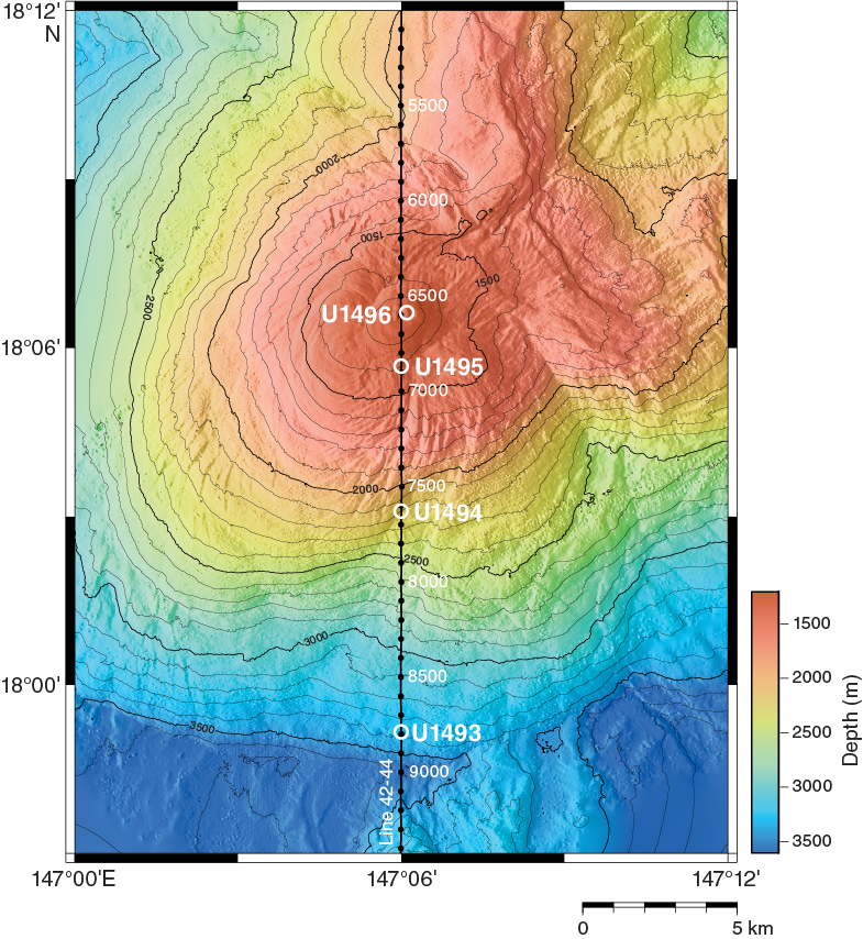
Figure F1. Bathymetric map, Sites U1493–U1496.
Drilling at Site U1493 on the deep lower flank was expected to recover some of the oldest serpentinite mudflow materials on the edifice (Figure F2). We anticipated recovering muds and rock clasts that would provide information regarding the lithology of these early erupted materials. Potentially, serpentinized peridotite clasts and other lithologies may reveal different decollement pressure, temperature, compositional conditions, and earlier mantle stress signatures from those that would be expected at the shallower (younger) sites on the edifice. We also expected that pore fluids had interacted with seawater after lengthy exposure at the base of the seamount. Such interactions may affect microbial communities present in the subseafloor environment. This site is underlain by pelagic sediment. Time permitting, our goal was to bisect this interval to constrain the age of the deepest flows and assess geochemical interactions between two distinctly different lithologies.

Figure F2. MCS Line EW0202 42-44 and Hole U1493B.
Drilling at Site U1494 was expected to penetrate the distal edge of a large and apparently coherent serpentinite mudflow (Figures F1, F3). High-resolution side-scan sonar imagery from a DSL-120 deep-towed vehicle shows low backscatter, suggesting the seafloor is covered with a layer of sediment. The distal edge of the mudflow feature has a maximum slope of about 20° and then flattens onto its upper surface, which has concentric ridges and arcuate semiradiating grooves. The expectation was that we would be able to date eruptive sequences on the flank of the seamount by paleontological dating of sediments between flow units to constrain rates and timing of serpentinite mudflow production.
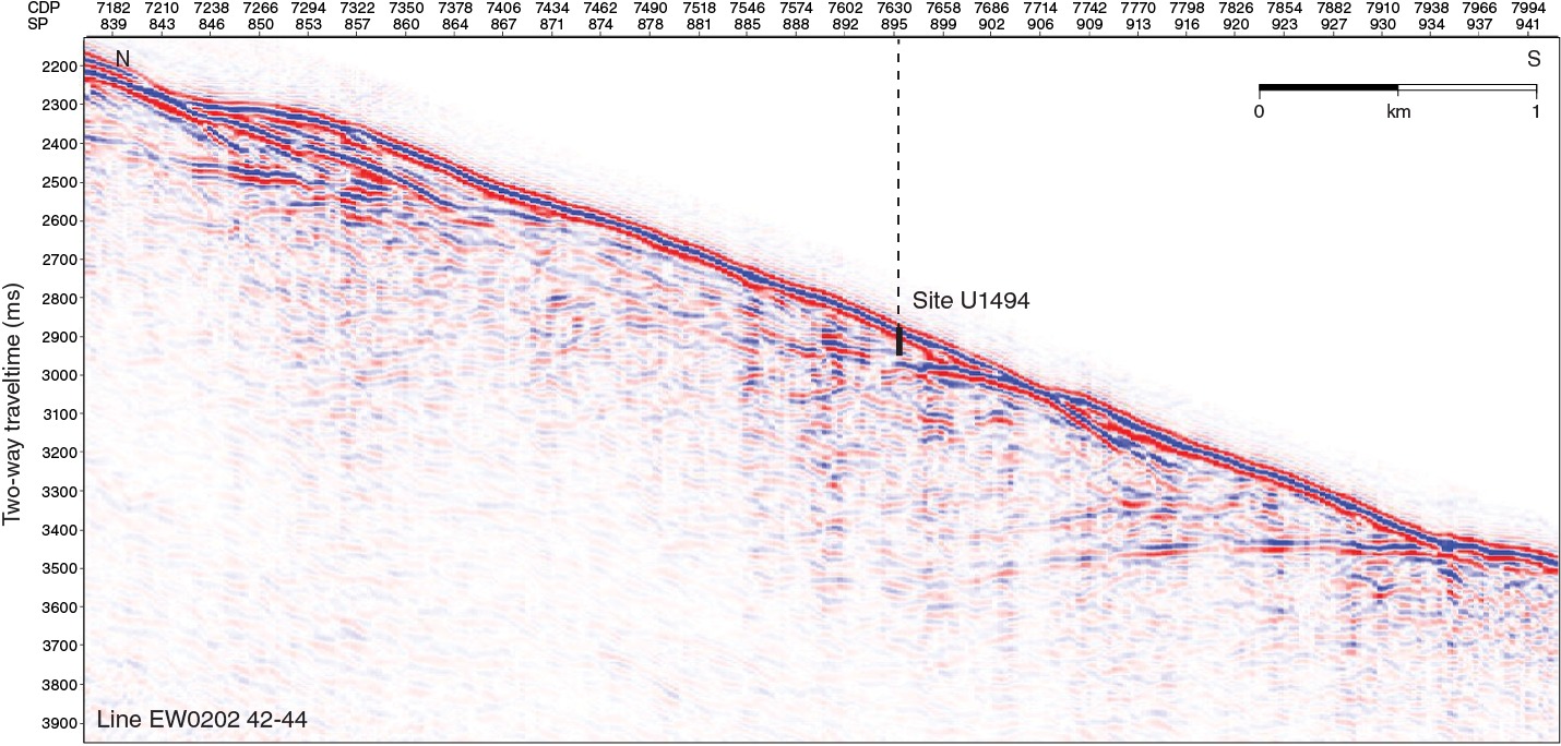
Figure F3. MCS Line EW0202 42-44 and Site U1494.
Drilling at Site U1495 was expected to penetrate the edge of a coherent serpentinite mudflow feature that overlies the larger mudflow targeted at Site U1494 (Figure F4). High-resolution side-scan sonar imagery from a DSL-120 deep-towed vehicle shows medium backscatter; based on the backscatter of summit features and observations with the remotely operated vehicle (ROV) Jason II, the medium backscatter intensity suggests that the seafloor at this site is covered with only a thin layer of sediment. The distal edge of this mudflow feature has a maximum angle of about 10°. The target mudflow at this location is about 7 km wide at its widest extent. The flow fans out from the summit about 6 km southwest. Its upper surface has concentric ridges and arcuate semiradiating grooves that are evident in the bathymetry data (Figure F1). The expectation at this site, as it was for Site U1494, was to date the eruptive sequences on the flank of the seamount by paleontological dating of potential sediment lithologies between mudflow units.
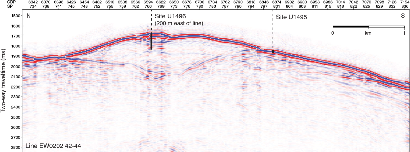
Figure F4. MCS Line EW0202 42-44 and Site U1495.
After experiencing considerable difficulties drilling with the half-length advanced piston corer (HLAPC) tool at Sites U1491 and U1492 (Yinazau Seamount), operational objectives were modified to provide first-order information at each of the three flank sites on Asùt Tesoru Seamount. Objectives were to core (HLAPC and extended core barrel [XCB] as necessary) one 50 m deep borehole at each of the three sites. Later in the expedition, after evaluating data from each site, we could return to one or more of these sites if time permitted to address secondary objectives and the possibility of coring a 300 m deep hole.
Coring a 50 m deep borehole at each of the three sites was intended to allow us to (1) intersect sediments and serpentinite mudflows and enclosed rock clasts on the deep southern flank and potentially date discrete mudflows paleontologically, as well as assess variability of mudflow composition and thickness; (2) investigate potential systematic variability in degree of serpentinization of the mud matrix and clasts; (3) examine transport conditions and the frequency and extent of transport; (4) assess pore fluid composition and the potential for serpentinization in old relict flows; and (5) collect samples for microbiological analysis to assess community dynamics in old flow materials that have exchanged fluids with bottom seawater.
Operations
Site U1493
Hole U1493A
The ship arrived at Site U1493 (proposed Site MAF-14A) at 0400 h on 4 January 2017 following a 136 nmi, 13 h transit from Site U1492 (all dates and times are ship local times). A reentry cone was set up in the moonpool in preparation for its use at Site U1496 at the summit of Asùt Tesoru Seamount, and the drill pipe was lowered through it. Sites U1493–U1496 form a ~14 km south–north transect from the foot to the summit of the seamount and are close enough for transit between them in dynamic positioning (DP) mode, allowing the same drill string to be used without being recovered and redeployed. Owing to the extra unscheduled time taken in casing Hole U1492D, we scaled back the drilling plan for the Asùt Tesoru flank sites (U1493–U1495) to one single 50 m advanced piston corer (APC)/XCB hole at each of these three sites. Hole U1493A was started at 3370.0 meters below rig floor (mbrf). While taking the first core from this site (366-U1493A-1H), the APC core barrel bent in two places. This core recovered 9 cm of mud with microfossils, and we decide to offset a short distance to avoid the hard zone or rock that bent the core barrel at this location (Table T1).
Table T1. Site U1493 core summary. Download table in CSV format. View PDF table.
Hole U1493B
The ship was offset 10 m east, and we started Hole U1493B at 1800 h on 4 January 2017, also at 3370.0 mbrf. An APCT-3 measurement was made on Core 366-U1493B-5F at 24.5 mbsf, obtaining a satisfactory temperature equilibration curve. Because of slow coring due to difficult APC/XCB drilling conditions and because we had sufficient samples for lithologic, geochemical, and microbiological assessment of the site, the decision was made to stop after Core 9X and move upslope 4 nmi to Site U1494. Hole U1493B penetrated 32.6 m and recovered 19.0 m (58%). The transit to the next site started at 1615 h on 5 January.
Site U1494
Hole U1494A
The ship arrived at Site U1494 (proposed Site MAF-13A) at 2050 h on 5 January 2017 after a 4 nmi transit in DP mode. The first core in Hole U1494A was taken at 2210.9 mbrf at 2325 h, and HLAPC and XCB coring became progressively more difficult with depth (Table T2). After Core 366-U1494A-11X took 2 h to drill, we decided to move on to Site U1495. Hole U1494A penetrated 39.0 m and recovered 29.6 m of core (76%). The short transit to Site U1495 started at 2135 h on 6 January.
Table T2. Site U1494 core summary. Download table in CSV format. View PDF table.
Site U1495
Hole U1495A
The ship arrived at Site U1495 (proposed Site MAF-12B) at 0115 h on 7 January 2017. The seafloor was determined to be at 1416.9 mbrf. The hole was unstable for drilling, and after each HLAPC core, an XCB barrel was run to drill down to the depth of the previous HLAPC core, resulting in two “ghost cores” containing mostly rock clasts. Elevated levels of hydrogen were found in Core 366-U1495A-2F, so we decided to core a second hole at this site to increase the number of microbiological and interstitial water samples. Hole U1495A penetrated 10.7 m and recovered 5.3 m (76%) (Table T3).
Table T3. Site U1495 core summary. Download table in CSV format. View PDF table.
Hole U1495B
The vessel was offset 25 m northwest, and Hole U1495B was started at 1320 h on 7 January 2017. The seafloor was at 1413 mbrf, ~4 m shallower than at Hole U1495A. Coring continued with the HLAPC coring system to a total depth of 10.8 mbsf. Once again, hole cleaning and a slow rate of penetration hampered progress to the point that operations were terminated because of hole conditions. Hole U1495B penetrated 10.8 m and recovered 10.8 m (100%). The transit to Site U1496 in DP mode began at 2100 h.
Lithostratigraphy
Three sites were drilled on the flank of Asùt Tesoru Seamount (Figure F5). The first site drilled (U1493) is the deepest at 3359 meters below sea level (mbsl) and is due south of and the farthest from the summit. The second site (U1494), at 2200 mbsl, is farther up the south slope, and the third site (U1495), at 1400 mbsl, is located just south of the summit mound.
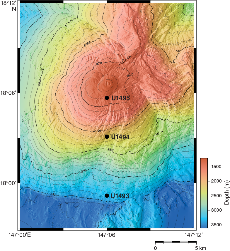
Figure F5. Bathymetric map, Sites U1493–U1495.
Cores recovered from several holes were divided into lithostratigraphic units based on the following criteria:
- Lithologic and mineralogical composition;
- Oxidation state of serpentinite mud matrix (highly oxidized brownish gray, oxidized greenish gray, or less oxidized bluish gray); and
- Percent of clasts within the serpentinite mud matrix, divided into serpentinite mud with clasts (clast percentage = 1%–3% or <1%), serpentinite pebbly mud (clast percentage = 3%–10%), and matrix-supported breccia conglomerate (clast percentage = 10%–50%), as well as hard rock intervals composed of cobbles or stones.
A general division for the drilled holes (from top to bottom) is as follows:
- Sandy–silty mud(stone) with foraminifers;
- Oxidized, brownish gray serpentinite (pebbly) mud with aragonite crystals and lithic clasts;
- Greenish gray serpentinite (pebbly) mud with lithic clasts and occasional layers of matrix-supported gravel; and
- Bluish gray serpentinite (pebbly) mud with lithic clasts occasionally containing layers of matrix-supported gravel and oxidized serpentinite mud with lithic clasts.
In general, the serpentinite mud/clast sequences are covered by brownish pelagic mud that contains foraminifers, nannofossils, and minor diatoms and radiolarians. The thickness of the pelagic mud sediments varies between sites and is approximately 80 cm in Hole U1493B, 0 cm in Hole U1494A, 6 cm in Hole U1495A, and 40 cm in Hole U1495B. The thickness of the red-brown oxidized serpentinite mud in the uppermost section of the recovered cores also varies upslope (approximately 40 cm in Hole U1493B, not including the interval sampled as whole rounds for interstitial water and microbiology, 1.40 m in Hole U1494A, 1.60 m in Hole U1495A, and 35 cm in Hole U1495B). Between 6.9 and 8.78 mbsf, Hole U1494A recovered an interval of mass flow sediments containing reworked serpentinite mud, volcanic ash, and brown muddy to silty fine sand with foraminifers that are assumed to be derived from upslope sedimentary deposits.
Site U1493
Sediment types recovered at Site U1493 include a range of lithologies, including pelagic clays and highly consolidated serpentinite mudflows (Figure F6).
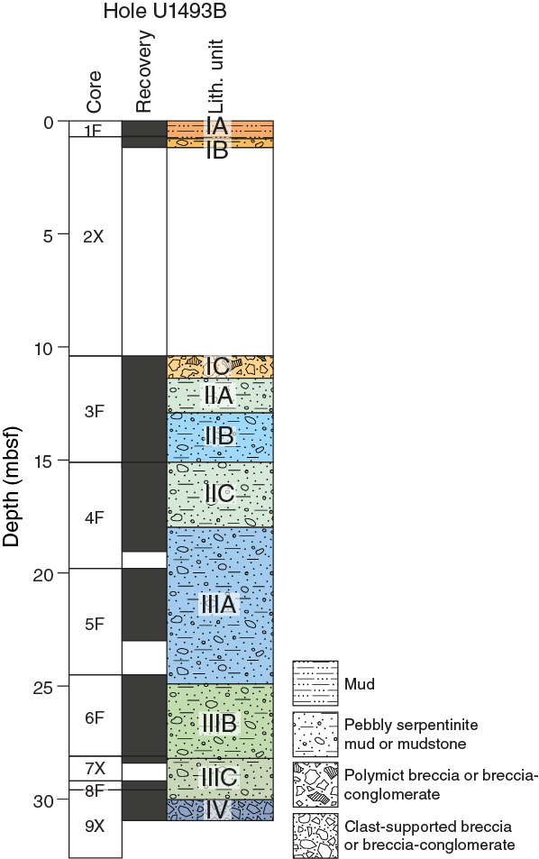
Figure F6. Lithostratigraphy, Hole U1493B.
Hole U1493A
The only recovery from Hole U1493A was 9 cm of brown pelagic mud in the core catcher. Foraminifers are common throughout the mud.
Hole U1493B
Hole U1493B cores are divided into four units (Table T4) with a total thickness of 30.96 m. Units I–III are further divided into nine subunits. A total of 9.22 m of core is missing between the bottom of Section 366-U1493B-2X-1 and the top of Section 3F-1 due to the switch to the HLAPC system from the XCB system and subsequent poor recovery (5%) in Core 2X. Drilling disturbance is common throughout the hole, varying from moderate to destroyed. Flow-in and up-arching are the most common disturbances.
Table T4. Lithostratigraphic units, Hole U1493B. Download table in CSV format.
Unit I
Subunit IA is 0.79 m thick and consists of dark gray-brown sandy silt with pelagic foraminifers that grades downhole into sandy siltstone.
Subunit IB is 0.39 m thick and consists of serpentinite matrix-supported polymict breccia–conglomerate with lithic clasts underlain by oxidized serpentinite mud with lithic clasts. The lithic clasts are dominantly serpentinized ultramafic rock, including harzburgites that are commonly oxidized to dark red-brown or orange-yellow. Clasts of fine-grained sandstone or siltstone are also common.
Subunit IB is followed by a gap in section of 9.22 m.
Subunit IC is 1.53 m thick and consists of pale brown serpentinite matrix-supported polymict breccia–conglomerate with lithic clasts. The lithic clasts are dominantly fine-grained brown sand- or siltstone in the upper half of the subunit (8%) and serpentinized or partially serpentinized ultramafic rocks in the lower half (2%–3%). The ultramafic rocks are commonly oxidized to dark red-brown or orange-yellow. Both clast types occur throughout this subunit.
Unit II
Subunit IIA is 0.99 m thick and consists of pale yellowish gray serpentinite pebbly mud that becomes paler at about Section 3F-3, 20 cm. This subunit contains about 2% clasts of serpentinized ultramafic rock, some of which are oxidized to red-brown or pale yellow-green. Some clasts are clearly harzburgites; others have no trace of their former mineralogy. Drilling deformation is moderate to severe, forming vertical lineations within the mud matrix.
Subunit IIB is 2.43 m thick and consists of greenish to bluish gray serpentinite pebbly mud with about 2% clasts of serpentinized ultramafic rock. The clasts are generally darker blue-gray than the matrix, and some retain relict harzburgite textures. Others are strongly deformed along with the matrix by drilling disturbance. Drilling disturbance is severe and includes both up-arching and flow-in textures. In Section 366-U1493B-3F-4, 27–33 cm, a flow-in feature includes an interval of light yellow serpentinite mud.
Subunit IIC is 1.98 m thick and consists of greenish gray matrix-supported monomict breccia conglomerate with 12%–15% clasts. The clasts are exclusively serpentinized ultramafic rock, some of which are relatively intact, whereas others contain abundant serpentine veins and have been shattered by drilling disturbance. The actual clast percentage could be as high as 50%–60%, but it is masked by drilling disturbance, which has fractured and deformed large clasts such that distinguishing clasts and matrix is difficult.
Unit III
Subunit IIIA is 6.91 m thick and consists of blue-green serpentinite pebbly mud with about 5% lithic clasts. The clasts are dominantly serpentinized ultramafic rock commonly altered to saprolite. Fall-in of reddish brown oxidized lithics (possibly sandy siltstones) from Unit I is apparent in about Sections 5F-1, 0–18 cm, and 6F-1, 0–20 cm. Drilling damage is extreme, with vertical flow-in features throughout the unit. Contorted plastic core liner was mingled with the serpentinite mud in Section 6F-1, 18–40 cm.
Subunit IIIB is 3.30 m thick and consists of light grayish green serpentinite pebbly mud with about 15% lithic clasts. The clasts are dominantly serpentinized ultramafic rock. Former large clasts are brecciated, probably before drilling, and exhibit white (ophicarbonate?) and pale green serpentine veins. These breccias are rebroken along veins due to drilling operations. Brecciated clasts are 2–3 cm across, with no flow orientation. Most clasts are <1 cm and vertically elongated with an aspect ratio of ~2:1. The matrix contains small (1–2 mm) whitish pinkish clasts that are irregularly distributed; they may be fragments of disaggregated carbonate veins. There is a strong vertically oriented flow fabric with grain segregations into coarser and finer bands that are likely drilling induced (flow-in).
Subunit IIIC is a 1.91 m thick mixed unit that comprises an upper 10 cm of fall-in from above, consisting of serpentinite matrix–supported small (<1 cm) clasts of a variety of materials from the uppermost part of the hole. Below Section 7X-CC, 10 cm, the unit consists of greenish to bluish gray serpentinite pebbly mud with about 50% lithic clasts. Among the clasts is a large harzburgite clast in Section 7X-CC, 10–18 cm. This single clast of serpentinized harzburgite nearly fills the core barrel and has greenish gray serpentinite mud adhering to it with none of the red-brown oxidized fragments characteristic of the fall-in above it.
From the top of the large clast to about Section 7X-CC, 24 cm, is serpentinite pebbly mud. The lowermost 7 cm of the section (7X-CC, 24–31 cm) contains several dark gray serpentinized ultramafic clasts that have sharp contacts with the enclosing darker gray serpentinite pebbly mud matrix. In Section 8F-CC, 0–44 cm, the unit consists of more of the greenish to bluish gray serpentinite pebbly mud and contains several large serpentinized ultramafic clasts. Two light gray clasts lie in Section 8F-CC, 4–18 cm. There are four small red-brown clasts (<3 mm in diameter) within this part of the unit, but the matrix is not soft, as is typical of the fall-in debris at the top of some cores.
The top of Section 9X-1, 1–12 cm, is similar to the base of Section 8F-CC, except it does contain a few red-brown fragments that possibly represent fall-in material from above. The matrix is firm, however. In Section 9X-1, 12–18 cm, a layer of clasts contains more of the red-brown fragments and more rock fragments in general. This layer rests on three dark gray serpentinized ultramafic clasts that lie in Section 9X-1, 18–32 cm, in loose gravel containing many pebbles of serpentinite and a few red-brown pebbles. In Section 9X-1, 38–51 cm, the matrix of greenish gray to dark gray matrix mud is crudely bedded. There are two dark gray serpentinized ultramafic clasts at the base of this unit (Section 9X-1, 48–54 cm). The unit then transitions to Unit IV.
Unit IV
Unit IV is 0.83 m thick and consists of a single (but broken) large (60.5 cm long) boulder of partially serpentinized harzburgite (Sections 9X-1, 54 cm, to 9XF-CC, 21.5 cm) with multiple generations of intersecting veinlets that crosscut a large serpentine-filled fracture. The intersecting veinlets resemble Frankenstein’s stitches (see Site U1493 in Petrology). This harzburgite appears to contain unaltered primary phases (orthopyroxene and olivine). Two cobble-sized serpentinized harzburgite clasts lie below this boulder surrounded by a dark gray serpentinized pebbly-mud matrix.
Site U1494
Site U1494 was drilled on the south flank of Asùt Tesoru Seamount, about halfway to the summit region (Figure F5). Only one hole was drilled at this site, to 35.73 mbsf, when conditions became too difficult to penetrate further. A total of 25 m of core was recovered using the APC and XCB systems.
Sediment lithologies recovered at Site U1494 comprise an uppermost unit of pale yellow-brown oxidized serpentinite mud underlain by moderately to highly consolidated serpentinite mudflows (Figure F7).
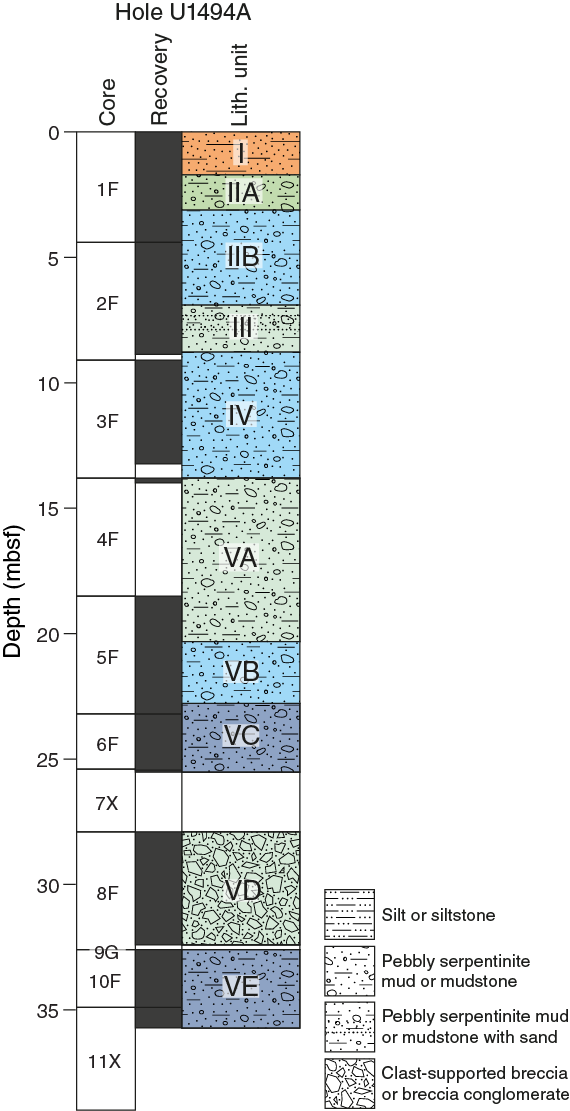
Figure F7. Lithostratigraphy, Hole U1494A.
Hole U1494A
Hole U1494A cores are divided into five units (Table T5) with a total thickness of 35.73 m. Unit II is divided into two subunits, and Unit V is divided into five subunits. A total of 2.38 m of core was not recovered before the onset of Section 8F-1 because of the switch from XCB to HLPC drilling. Drilling disturbance is common throughout the hole, varying from moderate to destroyed. Flow-in and up-arching are the most common disturbances.
Table T5. Lithostratigraphic units, Hole U1494A. Download table in CSV format.
Unit I
Unit I is 1.71 m thick and consists of pale yellowish green sandy serpentinite pebbly mud that grades downhole into grayish yellow green. It contains two patches of red-brown highly altered rock, one in Section 1F-1, 8–11 cm, and another in Section 1F-1, 17.5–20 cm. In Section 1F-1, 40–43 cm, is an elongate altered rock clast about 1 cm wide. A cluster of angular, dark gray rock fragments mottled with red-brown alteration patches and a red-brown halo on the upper surface occurs in the archive half of Section 1F-1, 48–52 cm. The angular fragments of dark rock clasts with mottled red-brown alteration also occur in Section 1F-2, 0–10 cm.
In Section 1F-2, 10–16 cm, there are two patches of red-brown discoloration in the mud, an upper one surrounding an angular brown rock fragment and a lower one surrounding a patch of dark gray granules. A large rock clast containing two prominent serpentine veins as wide as 2 mm lies in Section 1F-2, 60.5–71 cm. It has red-brown alteration patches that penetrate from 1 to about 2 cm deep into the rock, and the rock has a thin (<1 mm to about 1 cm thick) halo of altered, red-brown serpentinite mud surrounding it. Aragonite crystals, interpreted as authigenic, occur both as disseminated, randomly oriented, individual crystals in the mud matrix and as small, white variolitic clusters (<1 cm) throughout the unit, but they are more common in Section 1F-2, 0–52 cm. Severe flow-in drilling disturbance is observed.
Unit II
Subunit IIA is 0.65 m thick and consists of a mixture of greenish gray serpentinite pebbly mud with randomly oriented aragonite crystals to about Section 1F-3, 25 cm. This interval contains a few small (<1 cm) green clasts and small (<1 cm) patches of red-brown staining. Below Section 1F-3, 15 cm, the core is highly disturbed by drilling with significant flow-in and up-arching, with a dark gray layer that is smeared down the periphery of the core liner. In Section 1F-3, 26.5–28 cm, an arch of lighter greenish gray serpentinite mud pinches out below Section 1F-3, 28 cm, but is sucked in and broadens in Section 1F-3, 31–35 cm, on the left side of the archive half. In Section 1F-3, 28–52 cm, some light brown serpentinite pebbly mud also appears to be sucked in by the APC because it arches around a clast (Section 1F-3, 35.5–38 cm) in the dark gray serpentinite pebbly mud. In Section 1F-3, 52–75 cm, the light brown serpentinite mud that was sucked in to the core liner has pebbles with a larger grain size and two clasts about 2.5 cm in diameter with patches of red-brown alteration. The lithic clasts in this unit are dominantly serpentinized ultramafic rocks.
Section 1F-3, 75–150 cm, was sampled for microbiology, and no record is available.
Subunit IIB is 3.79 m thick and consists of bluish to greenish gray serpentinite pebbly mud. The lithic clasts are dominantly pebble-sized serpentinized ultramafic rock. A 4 cm radiating cluster of aragonite needles was recovered in Section 2F-1, 67.5–71 cm (Figure F8). The transition to Unit III is marked by a change in matrix color from blue-gray to pale green that grades over about Section 2F-1, 8–14 cm, via admixture of green matrix and red-brown and yellow-brown clasts into Unit III in Section 2F-3. However, critical aspects of this transition were lost due to whole-round samples for microbiology.
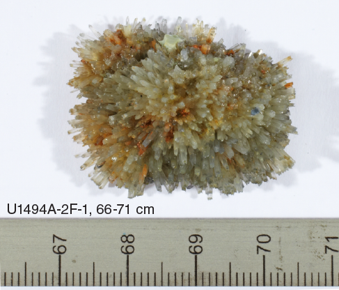
Figure F8. Aragonite crystal mass.
Unit III
Unit III is 1.88 m thick and consists of yellow-brown to red-brown serpentinite silty mud with 3%–5% clasts of serpentinized ultramafic rock. Lenses of pelagic silty sand with foraminifers are interbedded. The clasts of serpentinized ultramafic rock are commonly oxidized to red-brown or pale yellow-green colors. Some clasts are clearly harzburgites; others have no clear indicator of their protolith. The matrix is silty mud consisting of serpentinite mud and pelagic silt. The serpentinite mud is oxidized to yellow-brown. Drilling deformation from flow-in is moderate. This unit is interpreted as a mass flow deposit derived from upslope sedimentary deposits containing reworked serpentinite mud, volcanic ash, and brown muddy to silty fine sand with foraminifers.
Unit IV
Unit IV is 4.47 m thick, and in Section 2F-CC, 12–20 cm, there is dark gray serpentinite pebbly mud with about 2% clasts of serpentinized ultramafic rock. Beginning in about Section 3F-1, 0–37 cm, the serpentinite pebbly mud matrix is medium gray and has a loose, watery consistency (likely from above in the hole). This interval contains a mixture of clasts varying in color from dark gray to red-brown to light tan to white. In about Section 3F-1, 37–51 cm, the serpentinite pebbly mud matrix is light gray with two dark gray clasts of serpentinized ultramafic rock in Section 3F-1, 48–51 cm. In about Section 3F-1, 51–57 cm, the serpentinite pebbly mud is medium bluish gray and contains very few clasts. The number and sizes of the clasts increase downhole in Section 3F-2, and this section contains an altered ultramafic clast with a red-brown rim and veins in Section 3F-2, 26.5–28 cm; a medium greenish gray, spindle-shaped clast in Section 3F-2, 60–63.5 cm; and a light greenish gray clast, 4.5 cm long by 3 cm wide, with several fracture traces running through it in Section 3F-2, 79.5–84 cm.
The same bluish gray serpentinite pebbly mud matrix appears in Sections 3F-3 through 3F-CC with about 2% clasts of serpentinized ultramafic rock. However, Sections 3F-4 and 3F-CC contain a few very small (<2 mm) white to light tan clasts. The larger clasts are generally darker blue-gray than the matrix, and some retain relict harzburgite textures. Other clasts are strongly deformed, along with the matrix, by drilling disturbance. Drilling disturbance ranges from slight to severe and includes both up-arching and soupy textures. Soupy textures are confined to the top and bottom of the unit, obscuring contact details.
Unit V
Subunit VA is 6.52 m thick and consists of fall-in material from higher up in the hole in Section 4F-CC and from the top of the unit (Section 4F-CC, 0–36 cm) in Section 5F-1. Starting below Section 5F-1, 36 cm, the matrix is greenish gray pebbly serpentinite mud with at least 20%–30% clasts. The clasts are serpentinized ultramafic rock, some of which are relatively intact, whereas others contain abundant serpentine veins and have been shattered and distorted by drilling disturbance. The actual clast percent could be as high as 50%–60%, but it is masked by the drilling disturbance, which has fractured and deformed large clasts so that distinguishing clasts from matrix is difficult.
Subunit VB is 2.46 m thick dark blue-gray serpentinite pebbly mud with pale green vertical streaks. The clasts are apparently serpentinized ultramafic rock, but they are highly altered and severely deformed by flow-in (see Site U1494 in Structure). Drilling damage is extreme, and this unit is categorized as “destroyed” in the Drilling deformation tab in DESClogik.
Section 5F-4, 89–118 cm, was sampled for microbiology, and no record is available.
Subunit VC is 2.74 m thick medium bluish gray serpentinite pebbly mud with 10%–40% clasts (serpentinized ultramafic rock). This subunit, like Subunit VB, is highly contorted by drilling flow-in, with stripes of pale green and blue-green matrix with stretched former clasts that are dark blue-black in color. It has a foliated gneissic texture (see Site U1494 in Structure) reminiscent of Alpine root zones, but these structures are caused by drilling disturbance (flow-in). The matrix is a mixture of pale blue-green, medium blue, and darker blue serpentinite mud. In Section 5F-CC, 7–15 cm, there are patches and smears of red-brown matrix and one clast in Section 5F-CC, 11.5–12.5 cm, that is itself red-brown (likely fall-in). In Section 6F-2, the matrix alternates from medium to dark gray serpentinite mud twice, and all four intervals show drilling disturbance (flow-in). Section 6F-3, 0–63 cm, continues the dark gray phase from the bottom of Section 6F-2, but a distinct mass of very dark gray serpentinized harzburgite fills nearly two-thirds of the core liner width in Section 6F-2, 12.5–42 cm. This mass is striped with light green serpentinite matrix (or breccia). The mass is stretched/smeared upcore, and even individual bastites have suffered deformation and are sheared upcore. The lowest part of the unit in Section 7X-CC also clearly consists of fall-in, with a coherent but irregular-shaped ball of highly contorted dark and light blue serpentinite matrix with lithic clasts in Section 7X-CC, 0–6 cm. Below this interval, clasts are largely ultramafic, enclosed in a medium gray serpentinite pebbly mud matrix, but there is also a 1 cm white clast (carbonate) and a variety of small (<1 cm) pebbles.
Subunit VD is 4.53 m thick and consists of greenish to bluish gray polymict serpentinite pebbly mud with about 10% lithic clasts. The original mudflow structure of the entire unit has been destroyed by drilling disturbance. Fall-in is present throughout Section 8F-1 and to about Section 8F-2, 0–14 cm. There is severe up-arching of the semiconsolidated mud, accompanied by extreme plastic deformation of clasts. In Section 8F-2, 59–64 cm, it appears that there may have been a second penetration because fall-in material in that interval arches around a highly distorted and vertically streaked dark gray serpentinite pebbly mud matrix interval. This bottom interval of Section 8F-2 is also vertically streaked with greenish gray serpentinite and thus is also deformed by flow-in. In Sections 8F-3 through 8F-CC, the material all appears to be fall-in from higher up in the hole. Much of Section 8F-4 was taken as whole rounds.
Subunit VE is 3.13 m thick and consists of dark bluish gray consolidated serpentinite pebbly mud with plastically deformed (by flow-in drilling disturbance) serpentinized ultramafic lithic clasts (see Site U1494 in Structure for a more detailed description of the structural deformation). The uppermost part of the unit (Section 10F-1, 0–79 cm) contains four domains, two with blue serpentinite matrix and two with green serpentinite matrix, each containing remnants of shattered and deformed clasts, with strongly up-arched contacts between the domains. Below this, in Sections 10F-2, 0 cm, to 10F-CC, 32 cm, the original mudflow structure of the unit has been destroyed by drilling disturbance, primarily flow-in, accompanied by extreme plastic deformation of clasts. The deformation has produced pronounced vertical striping of alternating bluish gray and light greenish gray layers and slightly undulating bands of alternating colored layering. Original serpentinized ultramafic clasts are stretched and plastically deformed into vertical boudinage structures parallel to the banding of the serpentinite muds.
The bottom of the unit (Sections 11X-1, 0 cm, to 11X-CC, 40 cm) becomes more brittle, and the drilling disturbance takes the form of fragmentation. Section 11X-1 contains four domains from top to bottom: (1) blue serpentinite mud with black serpentinized ultramafic clasts (0–15 cm), (2) dark blue serpentinite mud with shattered clasts of black serpentinized ultramafic rock containing white veins (15–25 cm), (3) a clast-rich zone with green serpentinite mud matrix (the clasts may be parts of a single shattered clast; 25–33.5 cm), and (4) green varicolored serpentinite mud with many small granules and a few larger clasts (33.5–43 cm). The clasts are all serpentinite or serpentinized ultramafic rock.
Site U1495
Site U1495 is at a water depth of 1400 m below the summit area of Asùt Tesoru Seamount (Figure F5). Two holes were cored: U1495A (4.84 m recovery) and U1495B (10.18 m recovery).
Sediment lithologies recovered at Site U1495 comprise uppermost microfossil-bearing pelagic clays underlain by moderately to highly consolidated serpentinite mudflows (Figure F9).
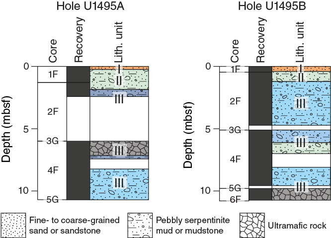
Figure F9. Lithostratigraphy, Holes U1495A and U1495B.
Hole U1495A
Hole U1495A cores comprise three units (Table T6) with a total thickness of 10.70 m. Unit I is grayish brown muddy fine sand with foraminifers, Unit II is mottled light green to grayish brown serpentinite mud with sand to matrix-supported polymict breccia conglomerate with a serpentinite clay matrix, and Unit III is bluish and greenish gray to grayish black serpentinite pebbly mud with lithic, mainly ultramafic, clasts.
Table T6. Lithostratigraphic units, Hole U1495A. Download table in CSV format.
Unit I
Unit I is 0.25 m thick and consists of grayish brown muddy fine sand with foraminifers. The sediments are soupy in consistency, indicative of severe drilling disturbance. However, Section 1F-1, 6–10 cm, has small (<1 cm) red-brown clasts surrounded by dark matrix, which is often characteristic of manganese oxide–coated sedimentary rock.
Unit II
Unit II is 1.45 m thick and consists of light green to grayish brown serpentinite pebbly mud with a sand and matrix-supported interval of small (~1 cm) rock clasts with a serpentinite clay matrix. The matrix contains scattered and randomly oriented acicular needles of aragonite. Lithic clasts, which are mainly serpentinized ultramafic rock, comprise about 8%–10% of the pebbly muds and range in size from granule to pebbles of <5 cm. The loose serpentinite pebbly mud is in Section 2F-1, suggesting that it may represent fall-in.
Unit III
Unit III is 9.00 m thick and consists of dark bluish gray to dark greenish gray coherent serpentinite pebbly mud. Lithic clasts are dominantly pebble-sized serpentinized ultramafic rock; small chips of pale green serpentine (which appear to be derived from disaggregated veins) are rare. Matrix aragonite is not found in this unit. Core 3G is a ghost core. Middle portions of the unit consist of a mixture of mainly serpentinized ultramafic rock with loosely adhering dark gray serpentinite mud and occasional red-brown fragments. Below this mixture, in Section 4F-1, 110 cm, the unit grades into angular serpentinized ultramafic pebbles that have very little to no serpentinite matrix mud. This portion of the unit continues to about Section 4F-2, 5 cm, and contains fall-in material from the layer above with minimal contribution from the shallowest part of the hole, suggesting that the ghost core, 3G, may have comminuted a boulder, pieces of which were recovered in subsequent cores, although we do not know the relative position of the ghost core. Lower portions of the unit consist of greenish gray to medium gray serpentinite pebbly mud with about 25% clasts of serpentinized ultramafic rocks. Streaks of the two colors of mud matrix and the clasts were distorted by drilling and show up-warping of the muds and stretching of the clasts. The lower part of this core section was removed as whole rounds. The bottom of the unit consists of soupy medium gray serpentinite pebbly mud with few and small (<<1 cm) clasts. In Section 4F-3, 12–20 cm, the serpentinite pebbly mud matrix is semiconsolidated, but this material is clearly flow-in. Core 5G is a ghost core with an upper 9 cm (Section 5G-CC, 0–9 cm) of mixed medium gray and stringers of light greenish gray serpentinite pebbly mud matrix with several small (<1 cm) clasts of serpentinized ultramafic rocks. In Section 5G-CC, 9–20 cm, the core contains up-arched thin stringers (<1 mm thick) of light greenish gray serpentinite mud within a generally dark gray coherent matrix of serpentinite pebbly mud with small (<1 cm) clasts of serpentinized ultramafic rocks. The core contains a larger broken clast (or three adjacent clasts) that fill the core liner in about Section 5G-CC, 20.5–24 cm.
Hole U1495B
Hole U1495B cores comprise three units (Table T7) with a total thickness of 10.74 m. Unit I is grayish brown muddy fine sand with foraminifers, Unit II is light green to grayish brown serpentinite mud with sand to matrix-supported polymict breccia conglomerate with a serpentinite clay matrix, and Unit III is bluish and greenish gray to grayish black serpentinite pebbly mud with lithic, mainly ultramafic, clasts.
Table T7. Lithostratigraphic units, Hole U1495B. Download table in CSV format.
Unit I
Unit I is 0.41 m thick and consists of pale brown to yellowish brown muddy sand and silt with foraminifers. There is a brown mud patch in Sample 1F-CC, 15–21 cm; otherwise, the sandy silts are moderately well sorted.
Unit II
Unit II is 0.81 m thick light greenish gray serpentinite pebbly mud with lithic clasts. The top of the unit contains fall-in serpentinite mud with ~20% lithic clasts, including reddish oxidized ultramafic clasts from Unit I (Section 2F-1, 0–37 cm). The lower half of the unit (Section 2F-1, 37–82 cm) is severely drilling disturbed, with fragments of shattered plastic core liner.
Lithic clasts, which are largely serpentinized ultramafic rock, comprise about ~10% of the pebbly muds below the fall-in. The serpentinite mud matrix contains aragonite crystals, which occur as acicular needles throughout the matrix.
Unit III
Unit III is 9.52 m thick dark bluish gray to dark greenish gray serpentinite pebbly mud. Clasts of pebble-sized serpentinized ultramafic rock form 8%–10% of the core. Acicular aragonite occurs in the uppermost 1 m of this unit, throughout the matrix. Drilling disturbance is mostly up-arching, which is relatively severe in the upper 40 cm of the unit and less pronounced downsection. Section 4F-1, 0 cm, to 4F-CC, 61 cm, is fall-in consisting of gravel derived from ultramafic rock produced by XCB drilling of the ghost core (3G). A single large boulder of massive dunite occurs in Section 3G-CC, 9–31 cm (estimated depth = 5.19–5.41 mbsf, but unlike anything recovered in the continuously cored units). This 22 cm diameter dunite is heavily serpentinized, without any orthopyroxene or bastite apparent on the cut surface. The dunite clast is cut by a dark weathered zone and by thin serpentine veins.
In Section 4F-1, 102 cm, the recovery transitions to light greenish gray to bluish gray serpentinite pebbly mud with 8%–10% lithic clasts of serpentinized ultramafic rock. Drilling disturbance remains moderate to severe up-arching. Most clasts are rigid enough to avoid deformation, but others show signs of stretching and folding.
At Section 4F-3, 0 cm, the mud transitions back to bluish gray serpentinite pebbly mud with 5% lithic clasts of serpentinized ultramafic rock. Drilling disturbance in this core section is moderate to severe flow-in. Most clasts are rigid enough to avoid deformation, but others show signs of stretching and folding. Core 5G is a ghost core with several clasts of serpentinized ultramafic rocks in its bottom half.
Toward the bottom of the hole, beginning in Section 6F-1, 0 cm, the recovery consists of gravel (85%–100% clasts), representing normally graded fall-in derived from large clasts destroyed by drilling, with all of the mud matrix washed out. The provenance of these clasts from horizons higher in the section is indicated by the occurrence of serpentinized ultramafic rocks that are oxidized to yellowish red.
Petrology
Site U1493
The clasts recovered from Site U1493 are dominantly serpentinized ultramafic rock with average sizes from granule to pebble. A single ultramafic clast, 51.5 cm thick, was found between Sections 366-U1493B-9X-1, 51 cm, and 9X-CC, 21.5 cm (Unit IV). In general, the ultramafic clasts in Unit I are reddish in color, suggesting overprint of secondary alteration oxide and/or sulfide minerals, whereas they are grayish black in the serpentinite mud in Units II–IV. Sandstones occur as dominant or subdominant clasts in Unit I.
Pelagic sediments
Brownish sandy to silty pelagic sediments containing microfossils and volcaniclastic fragments were recovered at the top of Holes U1493A (Section 1H-CC, 9 cm) and U1493B (Section 1F-1, 79 cm).
One smear slide (Sample 366-U1493A-1H-CC, 5 cm) of the pelagic sediments was prepared for Hole U1493A. It is composed of calcareous siliceous ooze with a few volcaniclastic grains. Microfossils are dominant, including foraminifers, radiolarians, sponge spicules (Figure F10), diatoms, trace ostracods, and silicoflagellates. Coccoliths are also common in the matrix. Volcaniclastic fragments mainly include pumice, feldspar, clinopyroxene, and glass.
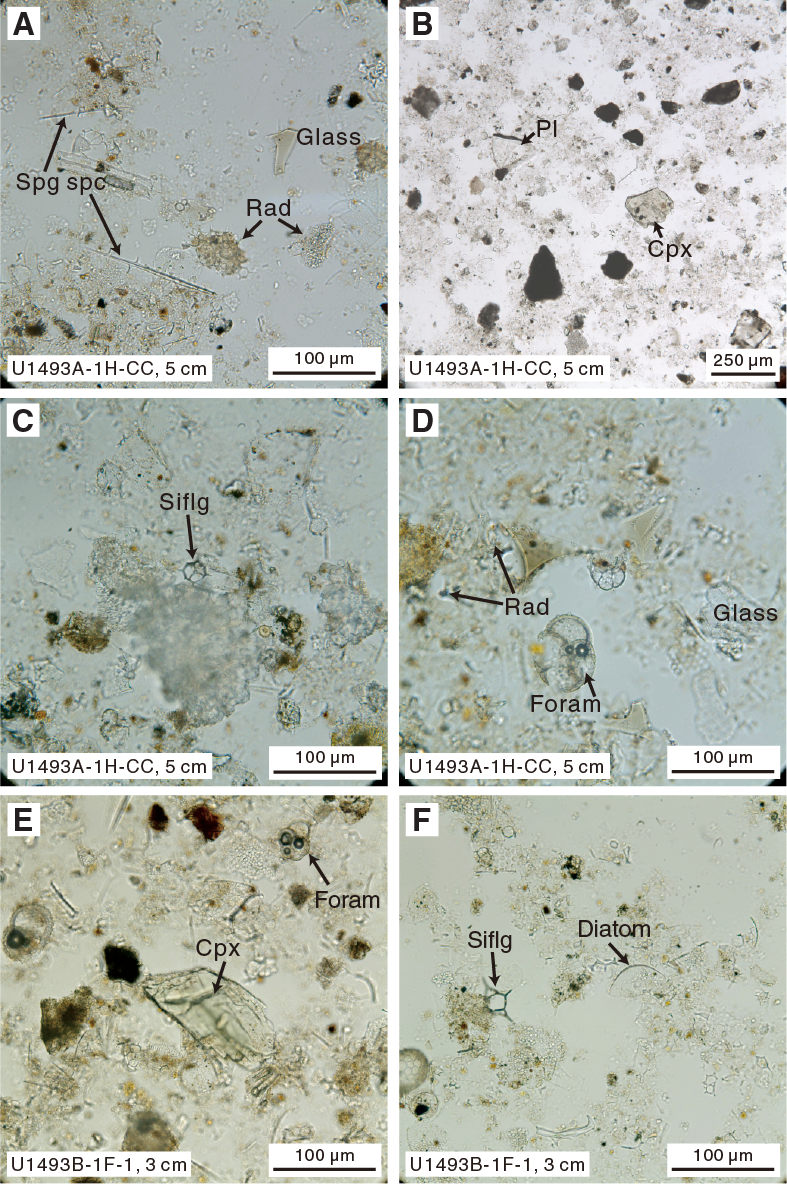
Figure F10. Pelagic sediments.
The one smear slide (Sample 366-U1493B-1F-1, 3 cm) of the pelagic sediments in Hole U1493B shows a composition similar to that of Hole U1493A sediments. Microfossils mainly include foraminifers, diatoms, calcareous nannofossils, radiolarians, and trace sponge spicules. A few fragments of feldspar and clinopyroxene are observed.
Serpentinite mud
The serpentinite mud in Hole U1493B is composed of silt- to clay-sized serpentine minerals with accessory Fe oxide (including magnetite or hematite), brucite, and spinel. Calcite and aragonite crystals, hydrogarnet, talc, tremolite, and chlorite were occasionally observed. The serpentinite mud in this hole mainly shows three colors: brown, bluish gray, and greenish gray.
Fifteen smear slides of serpentinite mud from Hole U1493B were made. Downhole changes in the smear slide results are shown in Figure F11. The compositional variation is accompanied by different colors of serpentinite mud. The highly oxidized brown serpentinite mud is mineralogically very different from the brown pelagic sediments. It is composed of transparent serpentine with ubiquitous small grains of Fe oxide (probably hematite), without any observed microfossils (Figure F12). Acicular aragonite is common in this layer. Both the greenish gray and bluish gray serpentinite mud intervals in the cores are mainly composed of colorless to light green serpentine, but they differ in that dusty grains of an opaque mineral (possibly magnetite) are widespread in the serpentine fragments of the bluish gray serpentinite mud, whereas similar dusty opaques are not that common in the smear slides of the greenish gray serpentinite mud, although large single anhedral opaque grains do occur. Anhedral hydrogarnet is common in this lithology, and chlorite was occasionally observed (e.g., Sample 3F-5, 76 cm). Volcanic glass and a fragment of diatom found in Sample 3F-4, 51 cm, indicate a pelagic input to the serpentinite mud.
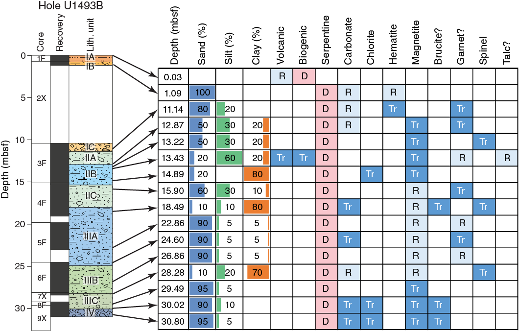
Figure F11. Downhole changes in mud composition, Hole U1493B.
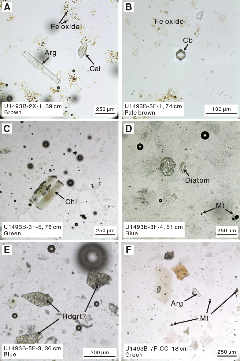
Figure F12. Serpentinite mud.
Serpentinized ultramafic rocks
Serpentinized ultramafic rocks are the dominant clast type recovered from Hole U1493B. They represent more than 90% of the clasts, although they make up merely 10%–50% of the clasts in Unit I. They are angular to subangular in shape and range in size mostly from <1 cm to a couple of centimeters (in one case up to 51.5 cm) on their long axis, with aspect ratios of ~1.5:1. Ultramafic rocks in Unit I are affected by an orange oxidative alteration that overprints serpentinization. In contrast, ultramafic rocks from other units are gray-green to dark gray.
Dunite
Sample 366-U1493B-3F-1, 106–126 cm (thin section [TS] 53), is serpentinized dunite (about 60% serpentinization) from Unit I. It consists of olivine grains crosscut by a mesh texture of serpentine-magnetite veins with interpenetrating textures. The olivine is altered and displays thinly recrystallized brownish rims. Olivine displays a wide range in grain size and can be up to 5 mm long; the average size is about 2 mm. Kink banding is common and clearly visible in the larger grains. Extensive deformation is also evidenced by olivine recrystallization forming fine-grained neoblasts of strain-free olivine about 50 µm wide. Spinel ranges to 3 mm in size; the average size is less than 1 mm. The extensive deformation and wide range in grain sizes suggest that the primary texture was porphyroclastic.
Sample 9X-1, 56–58 cm (TS 55), is slightly serpentinized dunite from Unit IV (about 30% serpentinization). The sample is gray and crossed by dark blue veins of serpentine (Figure F13). It is made of olivine porphyroclasts of various sizes, from about 50 µm to 6 mm in length, with an average grain size of ~3 mm. The larger grains are highly elongated, with kink bands parallel to the foliation. The primary texture was probably porphyroclastic. Olivines are crosscut by thin serpentine veins about 100 µm wide with pseudomorphic textures. Furthermore, large veins of serpentine of about 1 cm wide crosscut the sample. They are made of fibrous serpentine associated with chlorite (and/or brucite?) in the center and serpentine with interpenetrating textures at the rims.
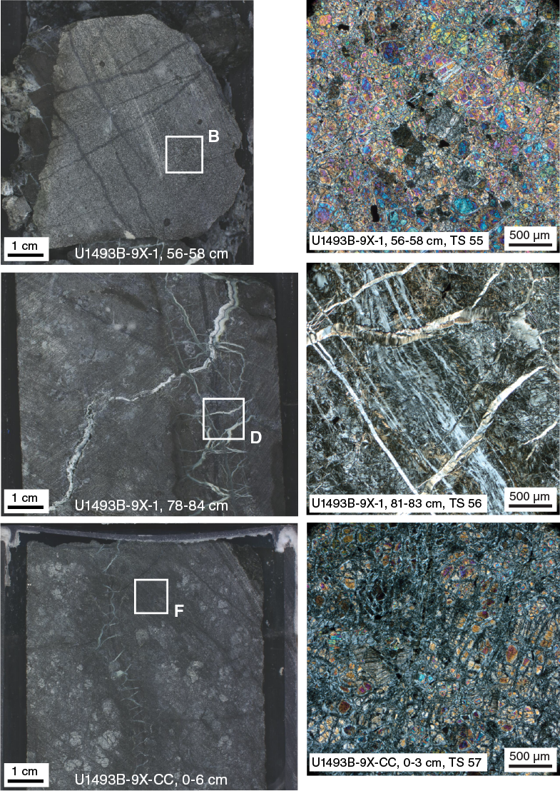
Figure F13. Serpentinized ultramafic clasts.
Harzburgite
Sample 366-U1493B-2X-1, 22–24 cm (TS 52), is serpentinized harzburgite (about 95% serpentinization) with pseudomorphic mesh, hourglass, and bastite textures. Mesh rims show a brownish alteration color. Rare olivine relics are preserved in the centers of brownish alteration aggregates. Minor amounts (≤2%) of clinopyroxene are preserved, typically as small interstitial grains molded to adjacent grain boundaries (possibly melt residues?). The sample is crosscut by two millimeter-wide serpentine veins.
Sample 9X-1, 17–18 cm (TS 54), is serpentinized harzburgite (serpentinization degree nearly 100%) with pseudomorphic mesh and bastite textures partly recrystallized into thin lamellae of serpentine with interpenetrating textures. The large abundance of bastite suggests that the protolith was an orthopyroxene-rich (about 30%) harzburgite. Large anhedral spinels as wide as about 3 mm were observed and are sometimes associated with a bright green mineral that may be secondary garnet (grossularite-uvarovite series) (Figure F14).
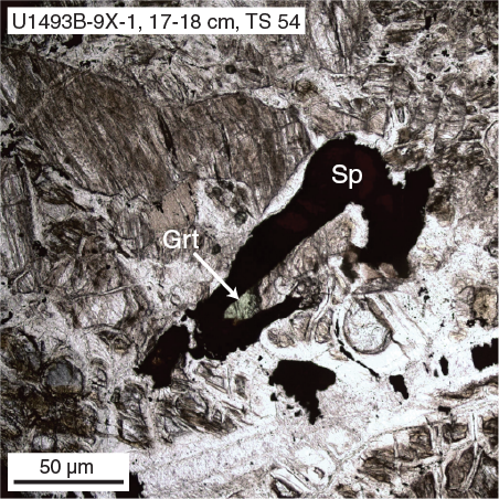
Figure F14. Chromian spinel.
Two thin sections (Samples 9X-1, 81–83 cm [TS 56], and 9X-CC, 0–3 cm [TS 57]) were made from the single 51.5 cm long clast recovered at the bottom of Hole U1493B. This clast is serpentinized harzburgite (about 70% serpentinization) crosscut by large serpentine veins (Figure F13). The host rock preserved round grains of olivine, pyroxene, and euhedral spinel embedded within pseudomorphic serpentine. The primary mode is estimated at 75%–80% olivine, 15%–20% orthopyroxene, and about 1% chrome spinel. Olivine and pyroxene are subequant and tabular, with olivine as large as 3 mm, orthopyroxene as large as 6 mm, and aspect ratios of about 2:1. Spinel forms irregular amoeboid grains occasionally associated with pyroxene, including trace amounts of clinopyroxene and more equant grains associated with olivine. The orthopyroxene and its bastite pseudomorphs are modestly deformed (minor kink bands), and both display fine exsolution lamellae of clinopyroxene or its alteration products. The discrete clinopyroxene grains may be granule exsolution from the orthopyroxene. The lack of strong foliation, the association of spinel with clusters of pyroxene, and the amoeboid shape of pyroxene-associated spinel suggest a primary protogranular texture.
The bastite domains of these thin sections are associated with anthophyllite or talc-like phases, most common at the termination of exsolution/cleavage flakes, but these phases also occur randomly within the centers. The vein centers are made of fibrous serpentine associated with chlorite (or brucite?), whereas vein rims display pseudomorphic mesh textures partly to fully recrystallized into interpenetrated lamellae of serpentine. The veins are crosscut by late conjugated fractures filled with fibrous serpentine, leading to a “Frankenstein”-like aspect at macroscale.
Carbonate rocks
One sample of carbonated ultramafic clast was prepared. Sample 366-U1493B-2X-1, 19–21 cm (TS 51), belongs to Unit I. It is a thinly recrystallized serpentinite composed of interpenetrating orientated lamellae of serpentine associated with magnetite and crosscut by large aragonite crystals as long as 5 mm. The aragonite is surrounded by a thin layer of brown (clay?) alteration.
Serpentine
Granule-sized green serpentine clasts are present in nearly all sections examined, although their abundances are typically <2%. These clasts appear to be pieces derived from thick veins during breakup of the clasts.
Site U1494
Site U1494 consists of serpentinite mudflows with entrained clasts. Dark gray serpentinized ultramafic rocks are the dominant clast type, except in Unit I, where red-brown lithic clasts including sandstone are dominant; these red-brown lithic clasts also occur in Section 366-U1494A-3F-1, 0–35 cm, where they appear to be fall-in from Unit I. Red-brown lithic clasts also occur as subdominant phases in close association with reddish serpentinized ultramafic rocks in Unit V, where the recovery is severely affected by drilling disturbance. Altered and serpentinized mafic rock clasts occur as subdominant clasts in Subunit VD. Drilling disturbance severely destroyed the primary textures of the serpentinite mud matrix and dark gray serpentinized ultramafic clasts, which are mingled and elongated in Unit V. The details of deformation textures are described and discussed in Site U1494 in Structure.
Fourteen smear slides were prepared of the serpentinite mud matrix. In addition, four representative clast samples were selected and examined by microscopic observation (Samples 366-U1494A-3F-2, 27–29 cm, 8F-1, 29–31 cm, 8F-4, 7–8 cm, and 8F-CC, 21–22 cm). The petrography of these samples is reported in the following sections.
Serpentinite mud
Serpentinite mud in Unit I (Sections 366-U1494A-1F-1, 0 cm, to 1F-3, 10 cm) is grayish yellow-green and mainly consists of fine sand– to clay-sized serpentine minerals with authigenic aragonite forming acicular crystals throughout (Figure F15).
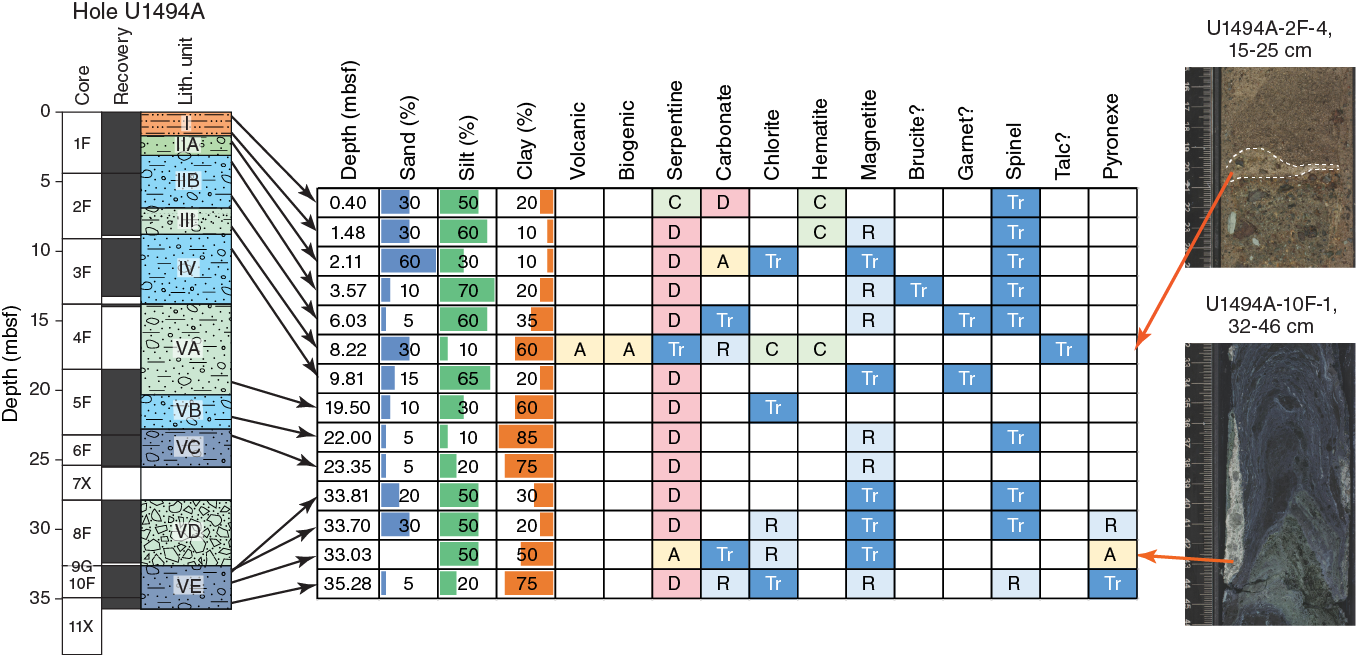
Figure F15. Downhole changes in mud composition, Hole U1494A.
In other units below 1.7 mbsf, serpentinite mud is composed of silt- to clay-sized serpentine minerals with accessory Fe oxide (including magnetite and hematite), brucite, and chrome spinel. The mud varies from light greenish gray or greenish gray to bluish gray to dark bluish gray. Without access to an X-ray diffraction analyzer, it was not possible to investigate what caused these different colors.
Serpentinite mud from excess material in the marine biology sample (2F-2, 85–95 cm) was wet sieved using 150 and 710 µm sieves and dried in an oven for several hours at 80°C. The 150–710 µm fraction of mud contains about 50% prismatic aragonite crystals, about 35% serpentine, about 10% altered ultramafic rock fragments, and about 5% magnetite and chromite. The large amount of aragonite results from a shallow sample depth (about 6.2 m) from the seafloor because aragonite is precipitated by interaction between rising pore fluids and seawater. The >710 µm fraction consists of about 50% subangular serpentine, about 40% serpentinized ultramafic rock fragments, about 9% euhedral prismatic aragonite crystals, and about 1% chromite. No metabasite was observed.
Downhole changes in the Hole U1494A smear slide results are shown in Figure F9. Smear slides show that the brownish mud in the uppermost part of the hole (Unit I) is mainly composed of serpentine, Fe oxide, aragonite, and trace spinel (Figure F16), without any microfossils. We suggest it is oxidized serpentinite mud rather than pelagic sediment. Subunit IIB is primarily bluish gray serpentinite mud composed of silt- and clay-sized serpentine (98%–99%) with small subhedral to anhedral grains of magnetite (<2 µm; 1%–2%) and trace brucite, spinel, and calcite. In Unit III, another layer of oxidized serpentinite mud contains lenses of pelagic sediments. The pelagic sediment mainly consists of sand- to clay-sized microfossils, volcaniclastic materials, and mud matrix. Microfossils mainly include foraminifers (20%) and diatoms (5%). Volcaniclastic materials include crystals of clinopyroxene (15%), plagioclase (10%), and chlorite (10%) and trace amphibole and glass; the mud matrix is composed of calcareous nannofossils (coccoliths; 10%), zeolite (1%), and other clay-sized calcareous sediment (10%). Fe oxide (9%) is quite common in the above minerals or in the mud matrix. Euhedral to subhedral aragonite is also quite common (10%). Trace serpentine was also observed.
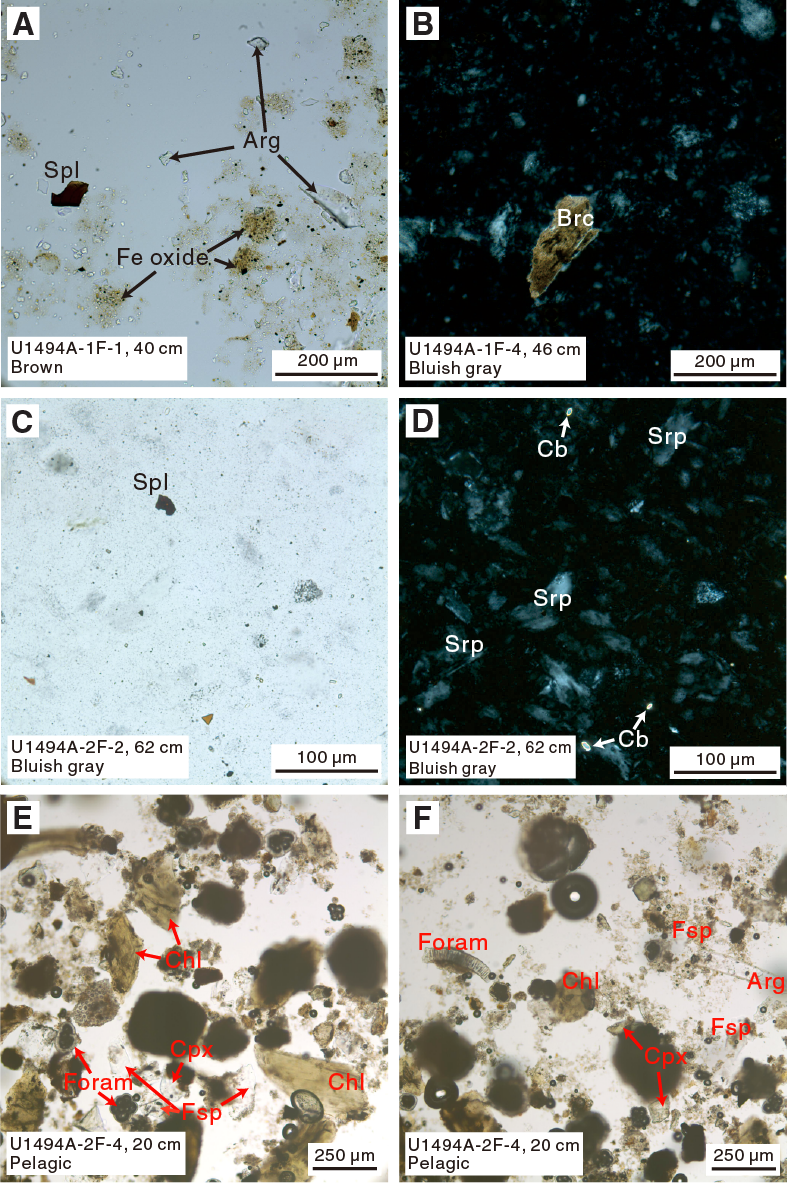
Figure F16. Serpentinite mud and pelagic sediments.
The dark bluish gray serpentinite mud in Subunit VB has distinctly euhedral magnetite grains (Figure F17), which are not commonly observed in the bluish gray serpentinite mud or the dark green serpentinite mud. In fact, the dark greenish serpentinite mud from a crushed serpentinite clast (Subunit VE) is composed of nearly pure silty serpentine mineral with trace spinel. Streaks of white-green mud in the severely drilling-disturbed zones in Subunit VA contain ~5% sand-sized serpentine/serpentinite and chlorite grains and dominant silt-sized anhedral to subhedral grains of an unidentified mineral (hydrogarnet?) with high relief and dark interference color in crossed polars. Another smear slide (Sample 366-U1494A-9G-CC, 4 cm) is made from the gray to light green mud, which is probably from a comminuted clast (Subunit VE). It is composed of sandy to clayey serpentine minerals (80%) with small-grain Fe oxide (1%), fresh to partly altered sand- to silt-sized clinopyroxene crystals (10%), chlorite (5%), and trace spinel and plagioclase. It is probably a mixture of serpentinite mud and comminuted metabasite.
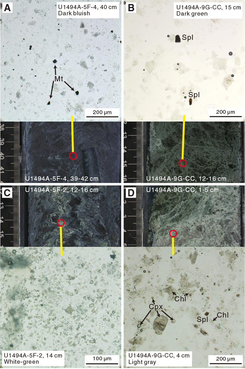
Figure F17. Serpentinite mud and other materials.
Serpentinized ultramafic rocks
Serpentinized ultramafic rocks are the dominant clasts at Site U1494, except for in Unit I and Section 366-U1494A-3F-1, 0–35 cm. The ultramafic rocks are largely dark bluish gray harzburgites and dunites. Harzburgites are recognized macroscopically by the occurrence of relict orthopyroxene or its pseudomorph bastite, which can be clearly seen on cut surfaces. Dunites appear similar but lack orthopyroxene or bastite pseudomorphs. Pyroxenites are difficult to distinguish macroscopically but are recognized in thin sections by the abundance of pyroxene or bastite.
Sample 366-U1494A-8F-1, 29–31 cm (TS 59), from Subunit VD is olivine-bearing orthopyroxenite. The rock is highly recrystallized (100%) to serpentine and related phases. Serpentine displays interpenetrating textures, relict pseudomorphic mesh textures, and bastites (Figure F18). The primary mineralogy consists of very large orthopyroxenes (now bastite pseudomorphs) as wide as 7 mm, with an average grain size of about 4 mm. There are some large olivine grains as large as ~3 mm (as determined by bounding bastites), but others are much smaller and fill spaces between the large orthopyroxene grains. Trace amounts of reddish brown spinel form small euhedral grains. This clast is probably derived from a vein or dike in harzburgite.
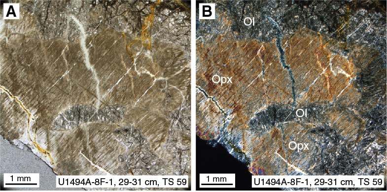
Figure F18. Serpentinized olivine orthopyroxenite.
Mafic igneous rocks
Mafic igneous rocks are a subdominant clast type, recognized macroscopically by their lighter color or in some cases a dark green color (greenstones). They often stand out from the dark gray ultramafic clasts, but this distinction may be obscured by mud coatings.
Three mafic igneous rock samples were examined for microscopic petrography (Samples 366-U1494A-3F-2, 27–29 cm, 8F-4, 7–8 cm, and 8F-CC, 21–22 cm). Sample 3F-2, 27–29 cm (TS 58), is metabasite with alternating white and green layers (Figure F19). The white layers are mainly chlorite with potentially amphibole needles. The green layers are made of yellowish minerals with high relief and birefringence, possibly epidote. Carbonate veins crossing the green layers were also observed.
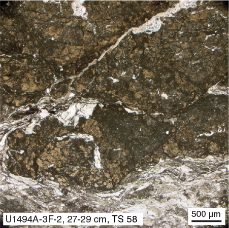
Figure F19. Metabasite.
Sample 366-U1494A-8F-4, 7–8 cm (TS 60), is sparsely olivine–plagioclase vitrophyre composed of tabular plagioclase (3%) and euhedral olivine (1%) phenocrysts, set in gray-brown altered glass or cryptocrystalline groundmass with tiny plagioclase microlites. The plagioclase phenocrysts are 200–900 µm in size and completely altered to sericite, phengite, and/or pyrophyllite (Figure F20). Olivine forms microphenocrysts (<0.2 mm) associated with chromian spinel and is completely altered to chlorite. Chromian spinel with sulfide and melt inclusions occurs as microphenocrysts (Figure F20). Vesicles are rare and filled with chlorite and epidote. Calcite veins represent the latest event in the evolution of the clast.
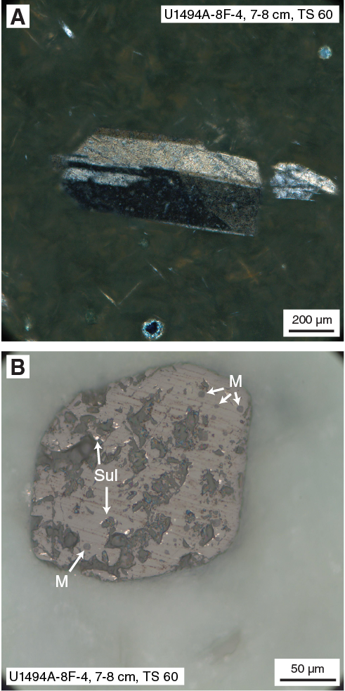
Figure F20. Sparsely olivine–plagioclase vitrophyre.
Sample 366-U1494A-8F-CC, 21–22 cm (TS 61), is olivine–plagioclase-phyric basalt (Figure F21). Euhedral, skeletal olivine phenocrysts (approximately 15%) are 0.3 to 1.2 mm across and completely altered to massive serpentine, often containing devitrified melt inclusions. Tiny chromian spinel inclusions are found in olivine pseudomorphs. Plagioclase laths as long as 1.6 mm and 0.1 to 0.4 mm across are completely altered to a low-birefringence phase. Plagioclase also contains melt inclusions in “swallow-tail” laths. Interstitial clinopyroxene is variolitic and partly altered to fibrous phases with lower birefringence color, probably chlorite. Oxides appear to be magnetite and sulfide. The texture is intergranular to variolitic and in places intersertal (patches of glass now altered).
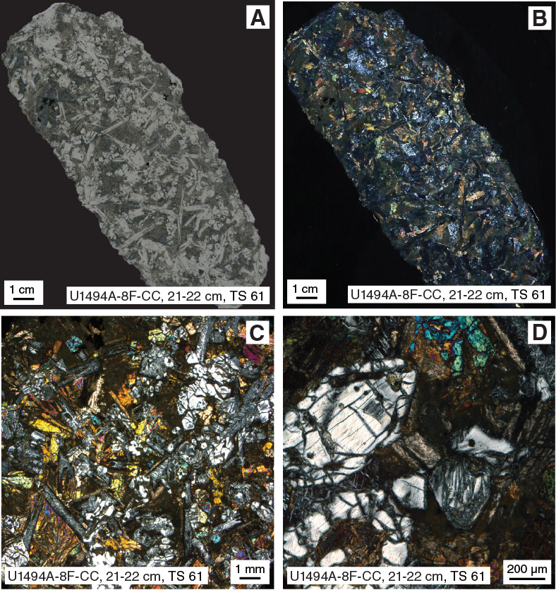
Figure F21. Olivine–plagioclase-phyric basalt.
Site U1495
Site U1495 consists of pelagic sediments and serpentinite mudflows with entrained clasts. Dark gray serpentinized ultramafic rocks are the dominant clast type in all cores, with rare pale green serpentine chips as the only subdominant clast type.
Pelagic sediment
Downhole changes in the smear slide results from Holes U1495A and U1495B are shown in Figure F22. Pelagic sediment in the upper 0.25 to 0.4 m of each hole is pale yellowish to gray-brown and consists of pelagic fine sand and clay. Microfossils are common, including foraminifers and radiolarians.
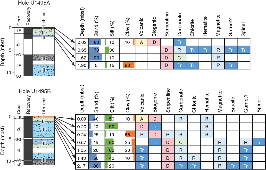
Figure F22. Downhole changes in mud composition, Site U1495.
For Hole U1495A, one smear slide (Sample 1F-1, 2 cm) of the pelagic sediments was prepared. It consists of siliceous calcareous ooze with volcaniclastic grains. Microfossils include dominant foraminifers (Figure F23), subdominant diatoms, and radiolarians. Small calcispheres are widely distributed in the clayey coccolith matrix. Trace amounts of silicoflagellates and calcareous nannofossils were also observed in the matrix, along with some sand-sized euhedral aragonite crystals. Volcanic materials include glass, pumice, lithics, and fragments of feldspar and clinopyroxene. The glass is colorless or light greenish or brownish and occasionally forms “spongy” texture, likely because of the presence of vesicles from exsolving of volcanic gases from the lava. Subhedral grains of plagioclase with fluid inclusions with vapor bubbles were also observed.
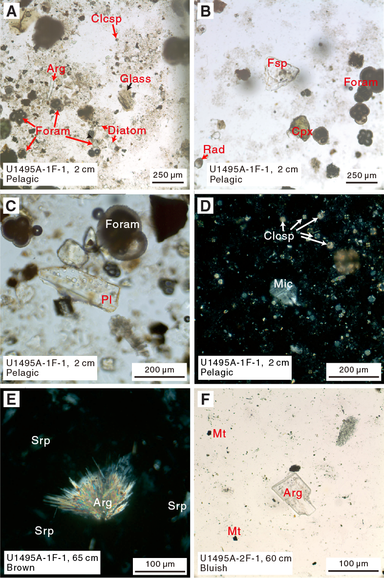
Figure F23. Pelagic sediments and serpentinite mud.
For Hole U1495B, three smear slides from the pelagic sediments were taken from ooze and a thin layer of volcanic sediments. The upper layer is composed of sand- to silt-sized brown siliceous calcareous ooze with volcaniclastic grains (Figure F24). Microfossils include dominant coccoliths and subdominant foraminifers, common radiolarians and calcispheres, and rare diatoms, sponge spicules, and calcareous nannofossils. Volcaniclastic materials include pumice, lithic grains (some may be dolerite or gabbro), colorless or light greenish to brownish glass, and fragments of feldspar and clinopyroxene. There are also some plagioclase grains with fluid inclusions. Sand-sized euhedral aragonite crystals are also included. The middle layer is composed of dark brown silt-sized volcanic ash. Vitric pyroclasts (pumice) are dominant in the matrix, with common crystal fragments of feldspar and pyroxene and trace amounts of olivine grains. Only a few foraminiferal fragments exist in the volcanic ash. The lower layer is sand- to clay-sized light brown calcareous ooze with rare volcaniclastic grains. Calcareous microfossils include foraminifers, calcispheres, coccoliths, and other nannofossils. Some U-shaped grains, typically 10 µm diameter, might be ceratoliths or calpionellids. Volcaniclastic fragments generally consist of clay-sized feldspar, clinopyroxene, pumice, and trace amounts of lithic grains. Sand-sized serpentine and acicular or radiated aragonite crystals were also observed in this layer.

Figure F24. Pelagic and volcanic sediments.
Serpentinite mud
In Hole U1495A, the color of the serpentinite mud gradually changes from yellowish brown in the upper portion to light greenish gray in the lower portion, whereas in Hole U1495B, it rapidly changes from light green to light greenish gray between Units II and III. The serpentinite mud of deeper units (below 1.7 mbsf in Hole U1495A and below 0.81 mbsf in Hole U1495B) ranges from bluish gray or dark bluish gray to less common light or very dark greenish gray.
Three smear slides of the serpentinite mud matrix were prepared for Hole U1495A, and four were prepared for Hole U1495B. In Hole U1495A, the serpentinite mud changes from yellowish brown to bluish gray. The brownish oxidized serpentinite mud in Hole U1495A consists of dominant sand- to silt-sized serpentine with aragonite. Aragonite displays two crystal habits: euhedral acicular crystals and small radial-fibrous crystals or aggregates (Figure F23). Magnetite is the dominant Fe oxide mineral, and some crystals are oxidized to reddish brown hematite. Trace amounts of spinel and chlorite are also found in the smear slides. The bluish gray serpentinite mud consists of dominant serpentine with tiny subhedral to anhedral magnetite inclusions. Trace amounts of carbonate and hydrogarnet were also observed in the matrix.
Scanning electron photomicrographs of the upper light greenish gray serpentinite mud unit in Hole U1495A (Unit II) reveal a mixed mineralogy. The serpentinite mud in this unit consists of radiating aragonite clusters, platy and fibrous serpentine, magnetite, and clusters of connected 1 µm spherical minerals (possibly amorphous silica or more extreme alteration of serpentine?) (Figure F25).

Figure F25. Greenish gray serpentinite mud.
In Hole U1495B, the serpentinite mud changes from yellowish green to bluish gray. The upper yellowish green serpentinized mud is composed of dominant silty to clayey serpentine (85%–93%), subdominant sandy acicular euhedral aragonite (5%–12%), minor magnetite (2%), and trace hydrogarnet (as much as 1%), glass, spinel, and microfossils (foraminifers and calcispheres) (Figure F26). The lower bluish gray serpentinite mud is composed of dominant sandy to silty serpentine (92%–94%) with small grains of magnetite (5%–6%); single grains or aggregates of magnetite are also common. Minor amounts of sand-sized subhedral to anhedral calcite fragments (trace to 2%) and trace amounts of chlorite (as much as 1%), brucite, glass, and hydrogarnet were also observed.
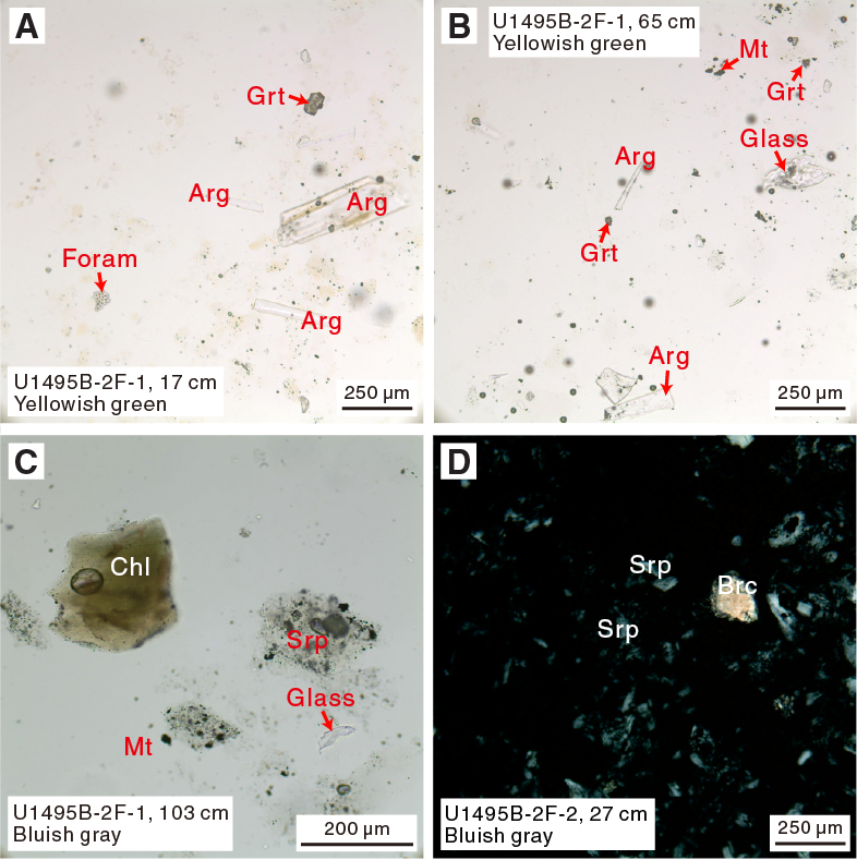
Figure F26. Serpentinite mud.
Serpentinized ultramafic rocks
Serpentinized ultramafic rocks represent the dominant clast type in all Site U1495 cores. Samples 366-U1495A-3G-CC, 13–15 cm (TS 63), 3G-CC, 18–20 cm (TS 64), 4F-1, 86–89 cm (TS 65), 4F-1, 86–89 cm (TS 66), and 4F-1, 88–90 cm (TS 67), are completely serpentinized and foliated rocks with nonpseudomorphic textures. They are characterized by mats of interpenetrating lamellae, possibly consisting of antigorite (shore-based analysis will be required to verify), that overprint older fabrics (Figure F27). Serpentine lamellae size varies from a few to hundreds of micrometers. The sample deformation is marked by crystallization of the oriented veins of magnetite and brucite that crosscut the serpentinite. Abundant fine-grained hydrogarnet crystals are present. Chromian spinel is rimmed by magnetite.
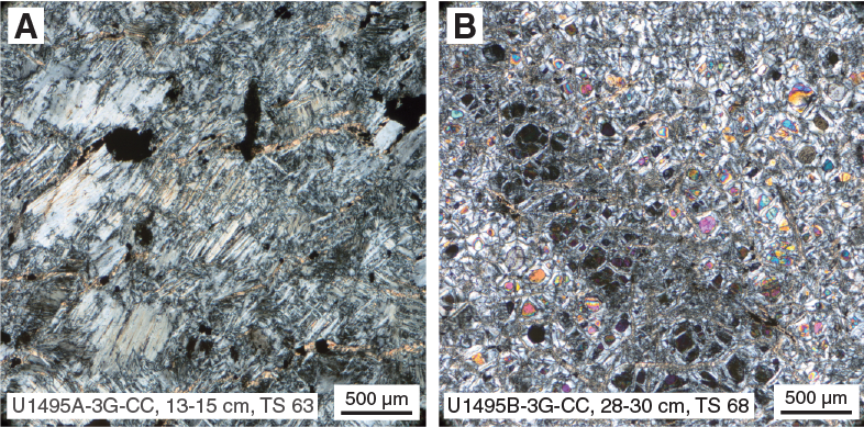
Figure F27. Serpentinite and serpentinized dunite.
A large clast cored with the XCB system in Hole U1495B (Sample 3G-CC, 28–30 cm [TS 68]) is serpentinized (>90%) dunite with relict olivine and euhedral chromian spinel that displays pseudomorphic hourglass fabric. Large contiguous zones of relict olivine with common extinction suggest that the primary grain size may have been about 6 mm × 2 mm and that elongate grains reached dimensions of 8 mm × 1.5 mm. These dimensions imply a strong primary fabric that may have been porphyroclastic or equant tabular/foliate. The sample is crossed by veins about 0.4 mm wide that are mainly composed of magnetite, serpentine, and brucite.
Structure
Site U1493
Structure observations were made on the mud matrix of the serpentinite flows and on individual clasts within the flows. Structures in the mud matrix are largely drilling induced. Structures within the clasts reflect deformation and the infilling of fractures to form veins prior to incorporation into the mud matrix, where they are not drilling induced.
Drilling-induced structures
Systematic vertical downward dragging toward the core liner flanks was observed in recovered mud in Sections 366-U1493B-2X-1 through 4F-3 (Figure F28). This dragging results in up-arching and pronounced flow-in drill disturbance structures. This type of drilling disturbance is described for Site U1492 (see Lithostratigraphy in the Site U1492 chapter [Fryer et al., 2018d]). Deformation is complex from Section 366-U1493B-4F-CC to the bottom of the hole. It alternates between vertical stripes from flow-in in Section 4F-CC to up-arching in Section 5F-1 to undulatory flow-in in Sections 5F-2 and 5F-3. There is fall-in and core liner incorporation in Section 6F-1. Up-arching, accompanied by undulatory flow-in and break-up of clasts, occurs through Section 6F-CC. From Section 7X-CC to the bottom of the hole, the structures show less up-arching and there are increasingly larger clasts with increasingly complex veining.

Figure F28. Drilling-induced disturbances.
Veins
Serpentine veins of various morphologies, geometries, and structures crosscut the host rocks occurring as large single serpentinite clasts in Core 366-U1493B-9X. These veins are described below (Figure F29).
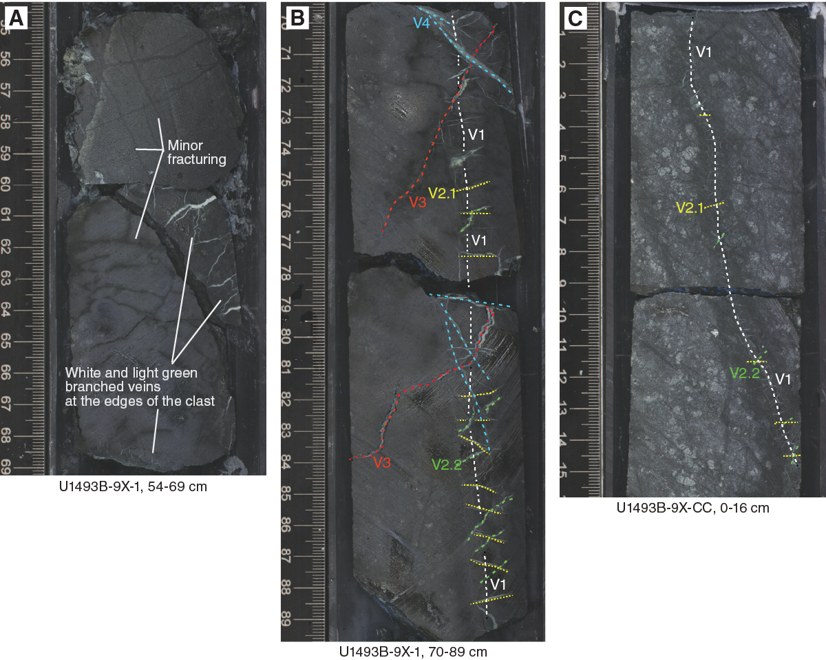
Figure F29. Serpentine vein geometry.
Minor fracturing was observed from the top of Section 9X-1 through Section 9X-CC. In Sample 9X-1, 55–66 cm, the network is composed of thin (<1 mm) fractures filled with black serpentine (chrysotile?). This network is composed of subvertical and subhorizontal fractures. In Sample 9X-1, 60–66 cm, pale green to white serpentine veins crosscut the edges of the clast. These veins are 0.4 to 2 cm long and 0.05 to 1 mm thick, single to branched, with an irregular morphology. The veins are parallel to the subhorizontal black fractures.
Primary subvertical black serpentine veins (chrysotile?) were identified within Sections 9X-1, 70–89 cm, and 9X-CC, 0–15 cm (Vein V1). Because the rock pieces are not oriented and the fragments of the boulder presumably rotated during recovery, it cannot be determined whether the veins observed on each piece of the boulder are a single vein or two similar veins parallel to one another.
The putative earliest vein type (V1) is crosscut by horizontal to subvertical crosscutting conjugate fractures filled with pale green serpentine with planar to sigmoidal shape (Vein V2). The thicknesses and the sizes of these veins decrease toward the bottom of the interval, from 1 cm long and 0.5 mm thick in Sample 9X-1, 70–77 cm, to less than 0.5 cm long and ~0.02 mm thick in Sample 9X-CC, 0–15 cm. Veins V2.1 and V2.2 often form conjugate sets with sharp contacts with the host rock; veins of type V2.2, however, are longer within the upper part of the section and have irregular shapes. This aspect, which could indicate pressure–dissolution sealing processes, is replicated at a larger scale on veins termed V3. Veins V3 are two large, single veins that are subparallel to Veins V2.2. In Section 9X-1, 70–84 cm, these veins thin from a width of 3 mm to ~0.1 mm; the upper vein gradually tapers into the host rock. The bases of Veins V3 are composite and seem to be symmetrical with a massive green serpentine central band surrounded by identical white bands.
Subvertical to subhorizontal massive serpentine veins (Vein V4) seem to crosscut all other vein sets. These veins reach a thickness of 2 mm.
A relative chronology of vein formation is difficult to reconstruct. Most veins appear to be the result of fracture sealing processes. Fracture formation and the sealing processed can be two different mechanisms. Veins V2.1 and V2.2 could be linked with dilatation induced by the serpentinization event that led to the formation of Vein V1. The higher concentration of broad serpentinite veins observed in the central part of the interval could indicate locations of the serpentinization initiation and subsequent extension.
Site U1494
Drilling-induced structures
Hole U1494A cores are almost entirely disturbed by drilling-induced structures. Downhole vertical dragging of the serpentinite mudflow packages toward the core liner flanks in Cores 1F, 2F, 3F, and 4F and flow-in during APC coring results in up-arching and pronounced disturbance structures, similar to the structures described for Sites U1492 and U1493.
Core 5F, the lower part of Section 6F-2, and Core 9G (from 0 to 42 cm) reveal structures related to suction of the serpentinite mud into the core barrel while pulling the drilling tools out of the borehole. This suction results in the contemporaneous development of irregular, partly ptygmatic, upward-verging folds in the upper part of the core (Figure F30) and a foliation-type penetrative fabric, including boudinage of both serpentinized clasts and foliation (Figure F31), in the lower part of the core. At the intersection with the core liner split surface, the folds are irregular with a wavelength ranging from a few millimeters up to 10 cm. The folds are developed along both core liner margins and are axially symmetric with respect to the suppositional split surface median line. Close to the top of the core, or in contact with pebble- to cobble-sized clasts, the folds form tight to isoclinal fold hinges because the upward-flowing serpentinite mud is confined by the top of the core barrel or the intercalated clasts that act as a backstop. The generally 3-D fabric is rotational and symmetric to the core axis, showing a sheath fold geometry. Intervals dominated by folds are Sections 5F-2, 0 cm, to 5F-3, 14 cm; 6F-1, 0 cm, to 6F-2, 25 cm; 6F-3, 0–53 cm; and 10F-1, 0–79 cm. Intervals dominated by stretching are Sections 5F-3, 14 cm, to 5F-4, 75 cm, and 10F-2, 0–125 cm. Strongly serpentinized clasts are elongated parallel to the core axis within the lower viscous mud matrix.
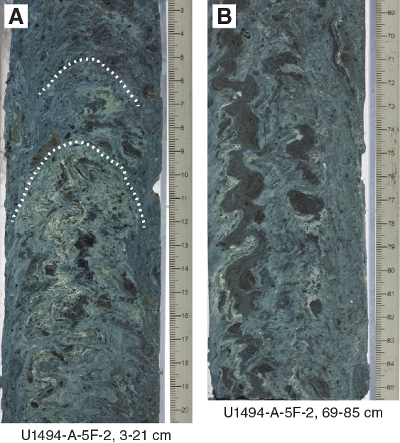
Figure F30. Drilling disturbance.
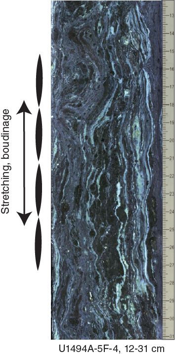
Figure F31. Drilling-induced stretching-related structures.
The pervasive flow-in of serpentinite mud implies that the retrieved core samples are not derived from their primary lithostratigraphic position. Distinction of lithostratigraphic units and definition of unit boundaries is, therefore, to a certain degree arbitrary.
Site U1495
Drilling-induced structures
As described for previous sites, structures induced by drilling disturbance vary in intensity. Most parts of the cores were drilled with the HLAPC system, resulting in downhole arching of all structural elements toward the core liner flank, especially in intervals characterized by low viscosity. These structures can be identified as flow-in, as seen in Section 366-U1495B-2F-1, 65–85 cm (Figure F32). Note fragments of broken core liner on the left side of the core image.
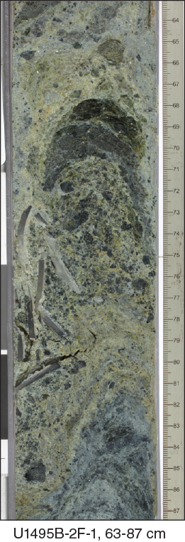
Figure F32. Drilling disturbance–induced structures.
Veins and fractures
An open fracture is recovered within a clast of Section 366-U1495B-3G-CC, 9–30 cm (Figure F33). This fracture is located along subvertical thin (<0.2 cm thick) serpentine veins preserved on the basal fracture plane. Detailed observations of the fracture plane on the bottom part of the clast show slight normal displacement (within the core liner reference frame) on the vein-containing surface. A potential strike direction could not be observed. The upper part of the fracture plane is altered, with almost no remaining vein material left, which could indicate that the fracture was open previously to drilling and is not drilling induced. This assessment is, however, highly hypothetical because the fracture-bearing clast is located in a ghost core. Two subparallel black veins crosscut the basal part of the fractured clast. These veins are irregular and haloed.
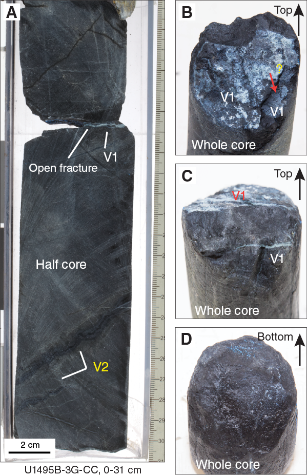
Figure F33. Open fracture.
Rock and sediment geochemistry
Elemental abundances for samples from Sites U1493, U1494, and U1495 selected by the shipboard scientific party were determined using inductively coupled plasma–atomic emission spectroscopy (ICP-AES) and portable X-ray fluorescence spectrometer (pXRF) analysis (Table T8). pXRF calibration curves are provided in Figure F2 in Johnston and Ryan (2018). The examined samples included serpentinite muds and serpentinized ultramafic rocks (harzburgites and/or dunites), along with a single sample of serpentinized cumulate rock. A full discussion of Expedition 366 rock and serpentinite mud data is found in Sediment and rock chemistry in the Expedition 366 summary chapter (Fryer et al., 2018b).
Table T8. ICP and pXRF data, Site U1493. Download table in CSV format.
Fluid geochemistry
Headspace analysis of H2, CO, and CH4
Interstitial water samples from Sites U1493–U1495 from the southern flank of Asùt Tesoru Seamount were analyzed for CH4 and other hydrocarbon concentrations by gas chromatograph (GC)–flame ionization detector (FID) because the GC–helium ionization detector (HID) instrument used for analyzing fluid from Sites U1491 and U1492 was out of order. Interstitial water H2 concentrations were measured using an electrochemical sensor, as described below (Figure F34). Interstitial water CO measurement capabilities were unavailable.
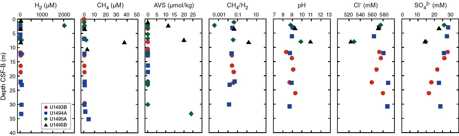
Figure F34. H2, CH4, and AVS.
Dissolved methane and ethane concentrations are low (<1 µM) in most samples and indistinguishable from CH4 concentrations in ambient air (Table T9). However, several serpentinite mud samples from deeper Sections 366-U1494A-10F-1 and 11X-1, 366-U1495A-4F-2, and 366-U1495B-4F-3 and 6F-1 have relatively high concentrations of CH4 and even C2H6. Among these samples, the sample from Section 366-U1495B-4F-3 has the highest concentration and is consistent with chemical signatures of interstitial fluids in cores from other serpentinite mud volcanoes, such as a relatively high pH value and low chloride concentration (Figures F34, F35). In addition, most of the CH4-enriched samples had low C1/C2 ratios (3–11). These ratios are consistent with subseafloor microbial functions, specifically the activity of anoxic methane-oxidizing sulfate reducers.
Table T9. Interstitial water methane and ethane concentrations determined by GC-FID. Download table in CSV format.
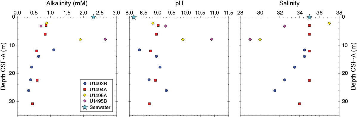
Figure F35. Alkalinity, pH, and salinity.
Electrochemical sensor measurements of H2 and H2S
Our modified interstitial water H2 measurements were conducted as follows. A 2 cm3 sediment sample was added to a 22 mL glass vial containing 18 mL of distilled water and HgCl2 as an antimicrobial agent. The vial was sealed with a Teflon-coated butyl rubber stopper and aluminum crimp seal. The glass vial was incubated at 80°C for 30 min and then cooled to room temperature (20°C). Dissolved H2 was measured via insertion of a coated needle electrochemical probe into the solution.
In most samples, H2 was detectable (Table T10). A sample obtained from Section 366-U1495A-2F-1 has a high concentration of H2 (2.03 mM). High acid volatile sulfide (AVS) concentrations were detected in the deeper zones (Sections 366-U1494A-10F-2, 366-U1495A-2F-1, and 366-U1495B-4F-3) (Table T10). These sulfidic horizons are associated with either H2 or CH4 enrichments. Thus, high H2 and CH4 in these interstitial fluids could provide potential energy sources for subseafloor chemolithotrophic microbial communities using sulfate as the electron acceptor. This result is consistent with interstitial water sulfate concentrations in Holes U1495A and U1495B (Figure F34). The CH4/H2 ratios indicate significant CH4-enrichment in the sample from Section 366-U1495B-4F-3, suggesting that microbial methanogenesis may occur within this zone.
Table T10. Interstitial water H2 and AVS concentrations determined by electrochemical sensors. Download table in CSV format.
Interstitial water
The salinity, pH, alkalinity, and chlorinity of the 14 interstitial water samples collected from Sites U1493–U1495 were measured within a few hours of sampling. Interstitial water samples were analyzed for NH4, PO4, and H2S by UV-vis spectrophotometry; Ca, Mg, K, Na, Br, sulfate, bromide, and chloride concentrations were measured by ion chromatography; and trace (Si, Li, B, Mn, Fe, Sr, and Ba) cation concentrations were measured using the shipboard Teledyne Leeman Labs Prodigy ICP-AES instrument. Major cations were not measured by ICP-AES because, given the likely elevated abundances of Na and K (e.g., Hulme et al., 2010), a multistage dilution process would have been required. The wavelengths examined for these elements are listed in Table T1 in the Expedition 366 methods chapter (Fryer et al., 2018a).
Salinity, pH, and alkalinity
Sites U1493–U1495 show distinct patterns of salinity variation (Table T11; Figure F35). Hole U1493B and U1494A salinities are near the seawater value of 35 at shallower depths and decline slightly (to 31 and 34, respectively) in the deepest samples. Samples from Site U1495 (two samples each from Holes U1495A and U1495B) appear to trend to lower values (29–30 at 8 mbsf).
Table T11. Interstitial water analyses. Download table in CSV format.
pH values are similar at Sites U1493 and U1494, ranging from 8.3 to 9.3 with no clear trends downhole (Figure F35). In Holes U1495A and U1495B, however, pH increases with depth: Hole U1495A samples increase from 8.7 to 9.8, and Hole U1495B samples increase from 9.25 to 10.8.
Alkalinity concentrations in Site U1493 and U1494 samples are lower (<1.1 mM) than seawater values, and downhole trends decrease slightly (e.g., from 1.1 to 0.3 mM in Hole U1493B and from 0.8 to 0.4 mM in Hole U1494A) (Figure F35). In contrast, measured alkalinities at Site U1495 are more similar to seawater alkalinities with values of 1.8 and 2.7 mM at ~8 mbsf in Holes U1495A and U1495B, respectively.
Ammonium, phosphate, sulfate and sulfide, chloride, and bromide
Measured ammonium concentrations in samples from Sites U1493–U1495 are above estimated seawater values (near zero) at the surface, with a maximum concentration of ~18 µM at 8 mbsf (Hole U1495B) (Table T11; Figure F36).
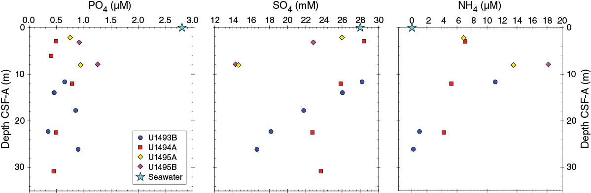
Figure F36. Phosphate, sulfate, and ammonium.
Phosphate concentrations (Figure F36) are lower than the bottom seawater value (estimated at 2.8 µM; Mottl et al., 2003) in samples from all three sites, varying between 0.3 and 1.2 µM. Samples from Holes U1493B and U1494A are consistently below 1.0 µM and show no variation with depth, whereas samples from Holes U1495A and U1495B are slightly higher at 1.2 µM.
In general, sulfate concentrations (Figure F36) decrease with depth in samples from Sites U1493–U1495. Hole U1493A and U1494A concentrations decrease from seawater values near the surface to as low as 16 mM below 28 mbsf, whereas Holes U1495A and U1495B have values slightly lower than seawater (at 27 mM) near the surface that drop to ~14 mM at 8 mbsf.
Hydrogen sulfide concentrations (Figure F36) were only detected in two samples, both from 8 mbsf: 10.9 µM in Hole U1495A and 2.2 µM in Hole U1495B. The analytical method used to measure hydrogen sulfide was modified to better evaluate lower concentrations, using the lowest range of the Cline method (detection limit = 0.1 µM; Table T11).
Chloride and bromide concentrations (Figure F37) are generally higher than typical seawater values. In Holes U1493B and U1494A, chloride increases from approximately 572 mM at 3 mbsf (11 mbsf for Hole U1493B) to 590 mM at 25–30 mbsf. Chloride concentrations in Holes U1495A and U1495B are less than seawater, approximately 525 mM at 8 mbsf. Patterns of bromide concentrations with depth are similar to those of chloride, with a slight increase from 0.93 mM at 3 mbsf to 0.98 mM between 10 and 20 mbsf followed by a slight decrease to 0.95 mM below 20 mbsf. The Na/Cl concentration ratio is equal to or higher than the seawater value for all fourteen samples.

Figure F37. Cl, Br, and Na.
Major and trace cations
Major and trace element abundances at all three sites show several distinct patterns of variation. In general, concentrations of K, Ca, Sr, and Na in interstitial water increase with depth in Holes U1493B and U1494A (Figures F37, F38). Na concentrations are higher than seawater values (466 mM) in samples from Holes U1495A and U1495B, ranging from <500 mM at 2–3 mbsf to a maximum of 543 mM at ~8 mbsf. Ca and Sr concentrations are lower than seawater values in the upper 10 m of the recovered material at each site. In Holes U1493B and U1494A, concentrations of these cations increase with depth: Ca increases from ~8.8 to ~14.6 mM and Sr increases from 81.5 to 118 µM in the deepest sample recovered. In contrast, Ca and Sr decrease to <1 mM and ~10 µM, respectively, by ~8 mbsf in Holes U1495A and U1495B. K concentrations are higher than seawater (10.1 mM; Mottl et al., 2004) in all holes and increase with depth (except the deepest sample in Hole U1494A), reaching 12.5 mM at ~26 mbsf in Hole U1493B and 11.9 at ~8 mbsf in Holes U1495A and U1495B.
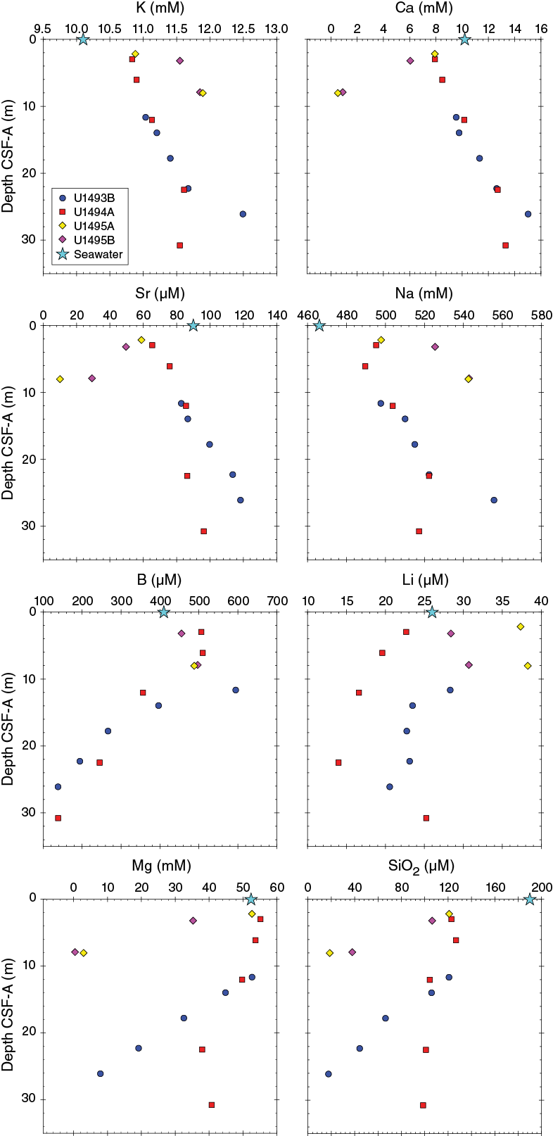
Figure F38. K, Ca, Sr, Na, B, Li, Mg, and SiO2.
B concentrations are higher than seawater values (410 µM) in the upper 10 mbsf in all holes; Hole U1493B records the highest B concentration of 595 µM. In Holes U1493B and U1494A, B content decreases to a minimum of 138 µM at 26.1 mbsf and 139 µM at 30.8 mbsf. Li concentrations are similar to seawater value (26 µM; Mottl et al., 2004) in Holes U1493B and U1494A. In Holes U1495A and U1495B, Li concentrations are higher than seawater with maxima of 38.3 and 30.8 µM at ~8 mbsf, respectively. Mg concentrations are close to seawater value (52.4 mM) in the uppermost 2–3 mbsf at Sites U1493 and U1494 and in Hole U1495A but are lower (35.3 mM) in Hole U1495B. In general, Mg concentrations decrease with depth, with some values <0.4 mM (below the limit of detection). SiO2 concentrations are markedly lower than seawater values (190 µM) in all fourteen samples. In Hole U1493B, SiO2 contents decrease by ~100 µM over 15 m to a minimum of 17.6 µM at 26.11 mbsf. The decrease in silica is less pronounced in Hole U1494A. In Holes U1495A and U1495B, the decrease in SiO2 is more rapid, dropping as much as 100 µM in ~5 m, with a minimum value in Hole U1495A of 38 µM at 7.9 mbsf. Mn concentrations (Table T11) are below the ICP-AES detection limit (0.07 µM) in Hole U1495A. In Hole U1493B, Mn concentrations are low with a maximum of 2.9 µM at ~18 mbsf. In Hole U1494A, Mn concentrations are significantly higher, ranging from 5.25 µM at ~3 mbsf to 11.98 µM at ~31 mbsf. Fe contents are below ICP-AES detection limits (<0.5 µM) in Holes U1493B, U1494A, and U1495A. In Hole U1495B, Fe concentrations range from 0.53 µM at 3.2 mbsf to 1.6 µM at 7.9 mbsf. Ba is consistently below ICP-AES detection limits (<0.015 µM).
Dissolved inorganic carbon/dissolved organic carbon
Dissolved inorganic carbon (DIC) concentrations (Figure F39) in Hole U1493B decrease from seawater values to a stable concentration of approximately a quarter of the bottom seawater concentration (~6 ppm). Concentrations in Hole U1495B samples vary from 4.7 ppm at 3 mbsf to 12.5 ppm at 8 mbsf.
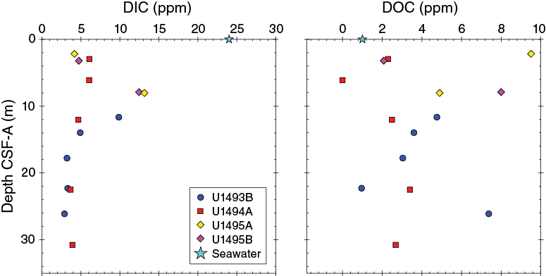
Figure F39. DIC and DOC.
Dissolved organic carbon (DOC) concentrations are scattered around the bottom seawater value (0.5 ppm; Eglinton and Repeta, 2014) in Holes U1493B and U1494A, varying between 1 and 4.8 ppm in Hole U1493B and between 2.3 and 3.4 ppm in Hole U1494A. In Hole U1495B, however, DOC reaches 8 ppm at 7.9 mbsf, significantly higher than the value of bottom seawater.
Summary
Sites U1493–U1495 are located on the southern flank of Asùt Tesoru Seamount. The interstitial water geochemistry reflects mixtures of seawater and a serpentinite interstitial water that was originally emplaced or trapped when the serpentinite muds erupted. The original emplaced interstitial water likely evolved with time (e.g., through continued water-rock reactions and/or microbial activity and diffusion). pH values are only moderately higher than seawater at Sites U1493 and U1494 but are significantly higher at Site U1495. K, Ca, and Sr concentrations are elevated in these flank sites. In contrast, B concentrations show a depletion pattern that may reflect B uptake into the serpentinite muds at a lower pH, as was inferred at Conical Seamount (e.g., Savov et al., 2005). Sulfate is typically enriched in the upwelling fluids for seamounts farther from the flank, but at flank Sites U1493–U1495, sulfate concentrations are depleted relative to seawater. Low sulfate concentrations and the presence of hydrogen sulfide in samples from ~8 mbsf in Holes U1495A and U1495B may result from microbial sulfate reduction.
Another distinctive marker for serpentinization is an elevated Na/Cl ratio (Mottl et al., 2004; Hulme et al., 2010). Relative to seawater (0.86), Na/Cl ratios for Sites U1493–U1495 are higher than seawater, and they increase with depth. Holes U1495A and U1495B have the highest Na/Cl ratio at depth, ≈1.0 at 8 mbsf.
Microbiology
Sample recovery
Microbiology sampling during Expedition 366 focused on exploring the limits of microbial life in serpentinite mud habitats across multiple depths using cultivation-based and cultivation-independent molecular biological approaches, microscopy, and assays for the detection of viruses. Sampling efforts targeted both near-surface and deeper whole-round cores, especially if there was evidence of transitions across gradients of microbiologically affecting compounds and gases (e.g., hydrogen, methane, hydrogen sulfide, and sulfate). Two 20 cm long whole-round samples were collected at each sampled depth for general microbial analyses. Additional whole-round samples were collected for individual investigations. A total of 16 whole-round samples were collected for general microbial sampling from the flank of Asùt Tesoru Seamount: five from Site U1493, seven from Site U1494, and four from Site U1495. These samples were preserved and will be analyzed postexpedition as described in Microbiology in the Expedition 366 methods chapter (Fryer et al., 2018a).
Contamination testing
Contamination assessment at Sites U1493–U1495 was conducted using perfluoromethyldecalin (PFMD). Tracer delivery was demonstrated by routine detection in drilling fluids and/or at the tops of cores when drilling fluid was absent due to expansion of the core during recovery. Only qualitative contamination control was practical because of limitations with the PFMD analytical method, so a conservative estimation of contamination was performed.
Successful tracer delivery is evident in Sections 366-U1493B-4F-2 (17.6 mbsf), 5F-2 (22.1 mbsf), and 6F-2 (24.5 mbsf) (Table T12; Figure F40). Low PFMD concentrations in Sections 3F-4 (13.8 mbsf) and 4F-2 (17.6 mbsf) indicate no intrusion of drill fluid.
Table T12. Summary of PFMD contamination assessment data, Site U1493. Download table in CSV format.
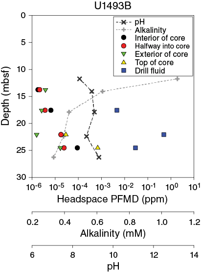
Figure F40. PFMD, Site U1493.
Successful tracer delivery could only be demonstrated in one section from Hole U1494A (2F-2; 6.5 mbsf) (Table T13; Figure F41). Detection of tracer decreases gradually from the contaminated top and exterior of the core toward the middle. Samples from the middle and halfway aliquots from Section 3F-3 (11.7 mbsf) indicate a similar contamination as that at the top of the core. The texture of Sections 5F-4 (22.1 mbsf) and 6F-2 (24.7 mbsf) made them impossible to sample on the catwalk because they were too hard to penetrate. No data are available for Section 8F-4 (30.5 mbsf), but pieces of core liner were found in the microbiology whole rounds, indicating heavy disturbance of the core and likely contaminated samples for microbiological analyses.
Table T13. Summary of PFMD contamination assessment data, Site U1494. Download table in CSV format.
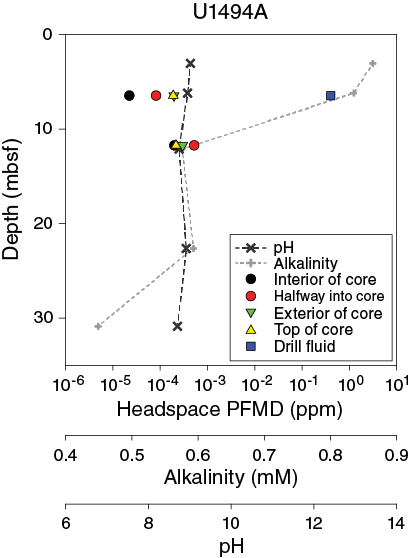
Figure F41. PFMD, Site U1494.
Only Section 366-U1495B-4F-2 (7.7 mbsf) shows anticipated results that confirm tracer delivery and low recovery of tracer in Holes U1495A and U1495B (Table T14; Figure F42). Section 366-U1495A-2F-1 (2.3 mbsf) shows low PFMD recovery but no proof of tracer delivery. Sections 366-U1495A-4F-2 (7.6 mbsf) and 366-U1495B-2F-2 (2.3 mbsf) do not allow an estimation of contamination with drill fluids.
Table T14. Summary of PFMD contamination assessment data, Site U1495. Download table in CSV format.
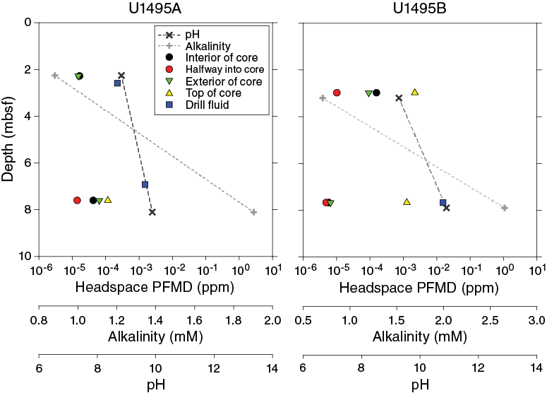
Figure F42. PFMD, Site U1495.
Physical properties
Physical property data were acquired for Holes U1493B, U1494A, U1495A, and U1495B, collected along a three-site profile on the southern flank of the Asùt Tesoru mud volcano. The Whole-Round Multisensor Logger (WRMSL) was used to measure wet bulk density using gamma ray attenuation (GRA), magnetic susceptibility, and P-wave velocity on the P-wave logger (PWL). The whole rounds were then logged for NGR. Discrete thermal conductivity measurements were performed on one or two whole rounds per core, depending on recovery. In addition, color reflectance, red-green-blue color space (RGB) intensities, and point magnetic susceptibility (MSP) were measured on the archive halves, whereas on the working halves, shear strength (automated vane shear) was measured and discrete samples were collected for moisture and density (MAD) measurements of wet and dry bulk densities (see Physical properties in the Expedition 366 methods chapter [Fryer et al., 2018a]).
Local but frequent core disturbance of the poorly consolidated mud deposits compromised the collection of P-wave velocity data on both the WRMSL and on the working halves. Poor core-to-liner coupling, incompletely filled core liners, core liner fracturing, and double thickness liners occurred often. These sections were associated with high signal attenuation. Although the PWL results are presented here, particular caution must be taken when interpreting this data set. Other data sets are mostly of good quality, except for some cores where the first sections were highly disturbed.
Physical property measurements were performed to help characterize the lithostratigraphic units and to describe the mechanical and thermal states of the serpentinite mud seamounts. Precise intervals of lithostratigraphic units and subunits from core description (see Lithostratigraphy) are used to describe physical property trends and calculate average values. For the figures, raw data were filtered to remove spurious points that correspond to empty intervals in the liner or broken pieces. All of the shipboard results and data interpretation are presented below.
GRA bulk density
Hole U1493B GRA density values reflect the two main lithologies (Figure F43). The pelagic sediment (lithostratigraphic Subunit IA) that occurs from the seafloor to 0.79 mbsf is characterized by a steady increase in density (from ~1.2 to ~1.6 g/cm3). Below this depth in the serpentinite mud (Subunits IB and IC and Units II–IV), densities range from ~1.5 to ~2.3 g/cm3 with a clear trend to higher values with increasing depth, reflecting compaction of the serpentinite muds. However, there is large variability in the bulk GRA density values, most of which is associated with intervals of drilling and coring disturbance.
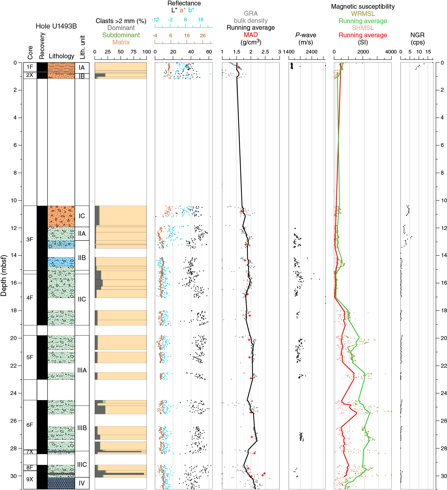
Figure F43. Physical properties, Hole U1493B.
Hole U1494A bulk GRA density values show large variability, partly due to lithology and partly due to drilling effects such as fall-in of material from the top of the hole (Figure F44). The values do not reflect the two main lithologies. From the top of the hole to ~22 mbsf, the running average GRA density increases from ~1.6 to ~2.25 g/cm3, most probably reflecting increasing compaction with depth. From ~22 mbsf to the base of the hole at 36 mbsf, GRA density values become more scattered, but no increasing trend is observed.
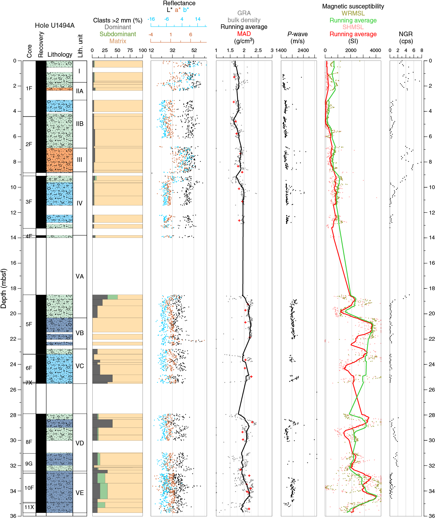
Figure F44. Physical properties, Hole U1494A.
Hole U1495A GRA density values (Figure F45) increase from ~1.5 g/cm3 in the uppermost pelagic sediments to ~2.3 g/cm3 at 2.6 mbsf. From 6 to 7.4 mbsf, GRA density values are very scattered due to core disturbance but are similar to those measured in the serpentinite muds of Holes U1493B and U1494A.
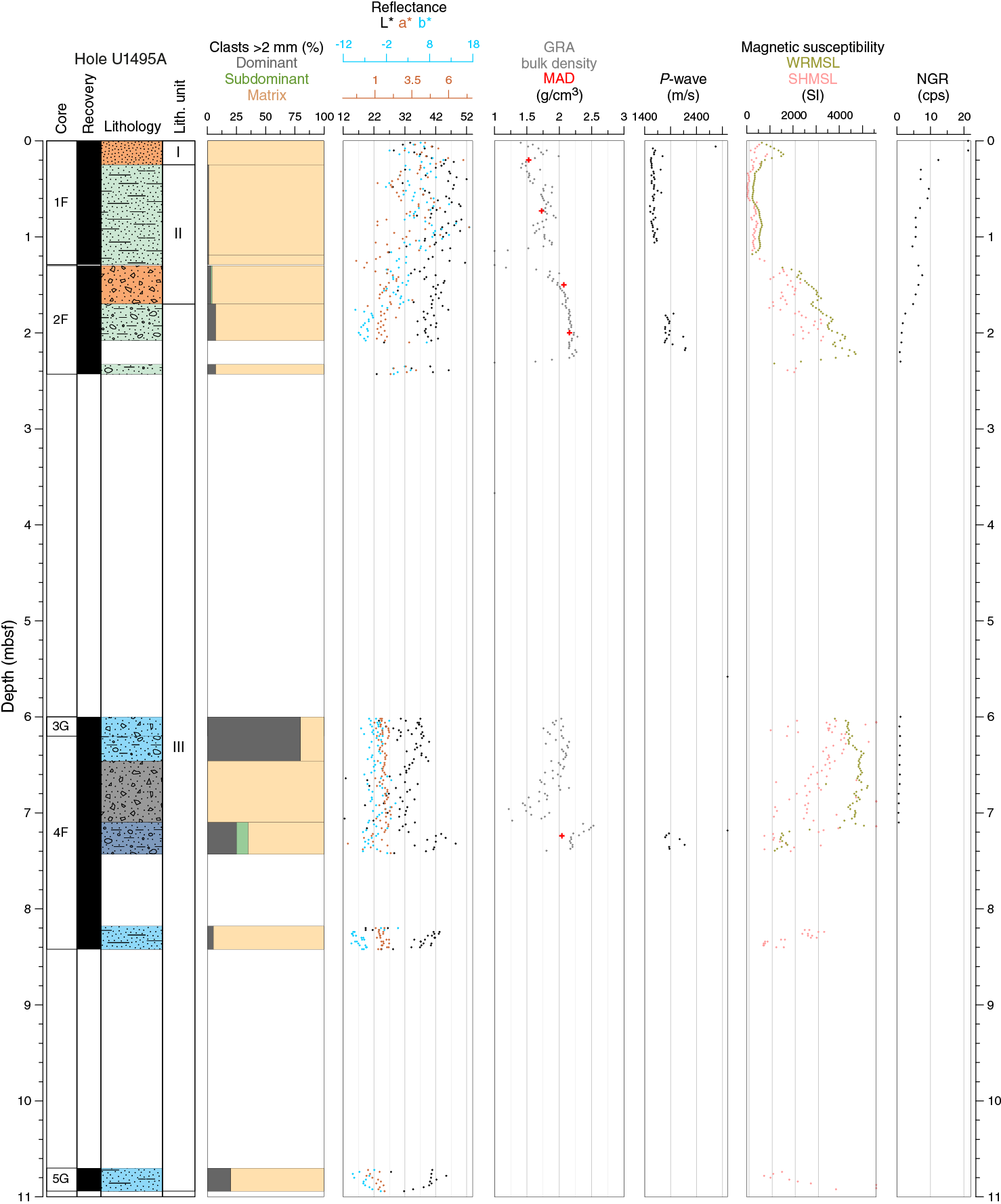
Figure F45. Physical properties, Hole U1495A.
Hole U1495B bulk GRA density values show large variability, partly due to lithology and partly due to drilling effects. The uppermost 2 m of the hole show a symmetrical increase and decrease in GRA density values, with higher values of ~2.1 g/cm3 at 1.2 mbsf and minimum values of ~1.7 g/cm3 at 0.5 and 2.2 mbsf (Figure F46). From 3.6 to 4.8 mbsf, GRA density decreases from ~2.5 to ~1.7 g/cm3. Below this depth, values are fairly constant, ranging between 2.0 and 2.2 g/cm3, except in the bottom 2 m of the hole where values are lower due to the recovery of pebbly clasts.
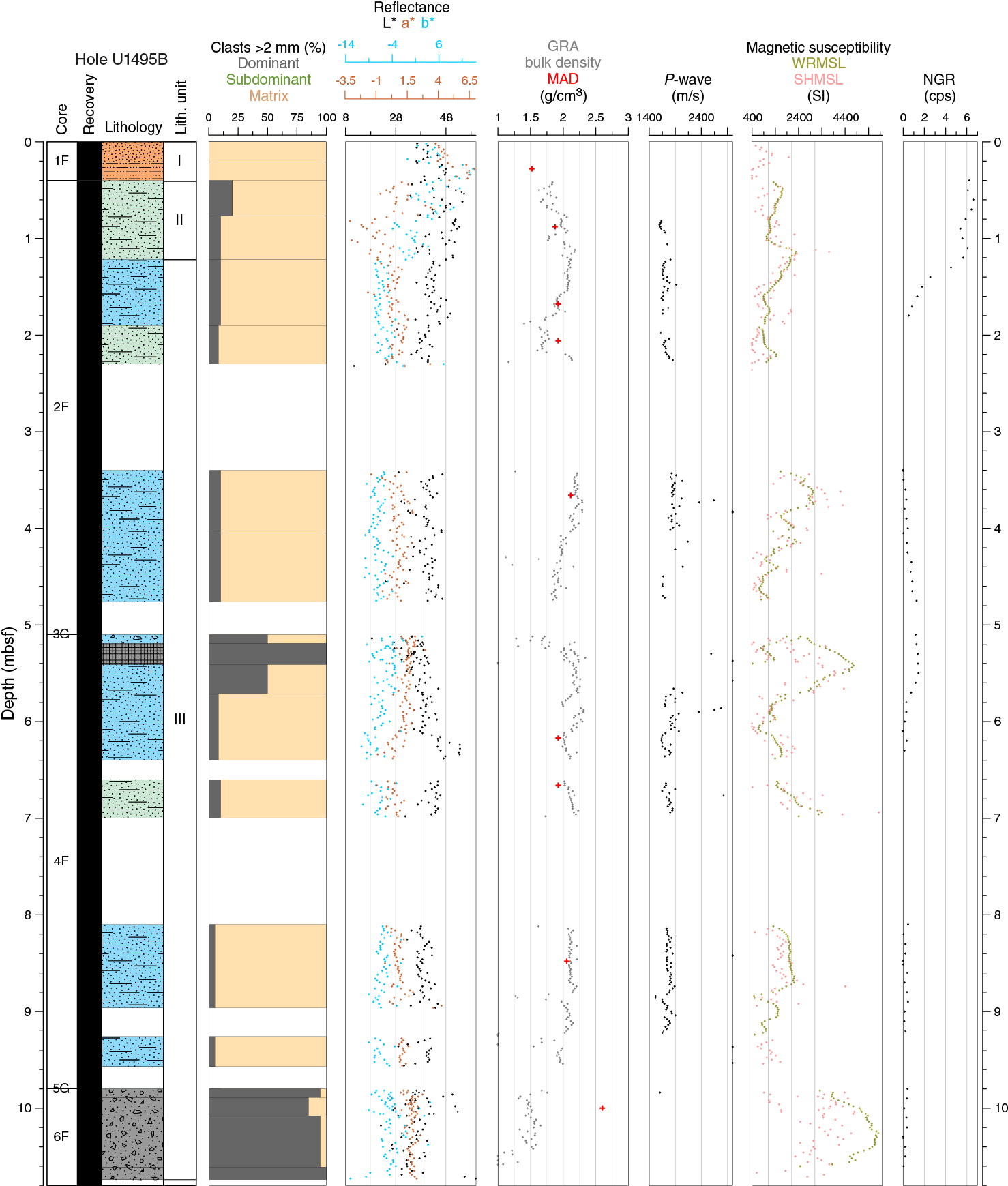
Figure F46. Physical properties, Hole U1495B.
The physical integrity of the recovered cores in all the holes presented in this chapter was not always ideal. The cores frequently exhibit intense disturbance, especially at the top, with remolded material and open voids inside the core liner. This disturbance results in anomalous physical property measurements, in particular GRA bulk density. Values indicating abnormally low bulk densities below 0.5 g/cm3 are obvious examples and are not included in the figures. In general, this coring disturbance results in large scattering of the point measurements, indicating erroneous values below the average described as typical for the two different lithologies (pelagic sediment and serpentinite mud). In contrast, GRA bulk density values above the average trends are correlated with the presence of clasts having higher density than the serpentinite mud matrix (28–29 mbsf) (Figure F44).
The GRA bulk density values are in good agreement with the MAD measurements. The data variations for the two methods track each other; however, the WRMSL GRA data frequently show slightly higher average values than those measured with MAD. This difference may be due to the loss of pore water that occurs between the two measurements. The subsampling for MAD occurs after the WRMSL measurement, and during the intervening time a small loss of pore water could occur.
P-wave velocity
Whole-round and discrete P-wave measurements were performed using the WRMSL and the calipers. However, the caliper failed to acquire data, despite the relatively low porosity in these cores. Therefore, only WRMSL data are used to describe P-wave velocity at Sites U1493–U1495. Due to difficulties recovering cored materials in their pristine in situ conditions, P-wave velocity measurements were not always possible within the required quality standards defined by the acquisition software. Consequently, the P-wave velocity records show several depth intervals with no velocity data. The P-wave velocity data is generally characterized by a large scattering of the values; however, a clear clustering of most of the values usually defines a minimum velocity threshold that is interpreted as the typical velocity of a particular lithology (e.g., pelagic sediments or serpentinite mud). The P-wave velocity data frequently shows dispersion above this threshold, indicating higher velocities, which are interpreted as reflecting the presence of large individual clasts or higher numbers of rock clasts that have P-wave velocities higher than the mud matrix. The main problems in getting reliable P-wave measurements at Sites U1493–U1495 include core disturbance, air bubbles inside the core liner, voids filled with seawater, and deformed core liners with double plastic layers.
P-wave velocity in the upper 0.79 m of Hole U1493B is constant at ~1540 m/s, corresponding to pelagic Subunit IA (Figure F43). Below this unit, the record is very scarce with large scattering of the velocity values but indicates a P-wave velocity threshold of ~1650 m/s, consistent with values measured in the serpentinite mud at other Expedition 366 sites. The velocity data points above this velocity threshold, which can reach as high as 2800 m/s, are interpreted as reflecting point measurements that include larger individual clasts or higher amounts of rock clasts with high P-wave velocities.
P-wave velocities in the upper 13 m of Hole U1494A show a threshold increase from 1480 to 1640 m/s (Figure F44). Below this depth, the available record shows a constant threshold value of ~1900 m/s, with the exception of the interval between 28 and 30 mbsf, where, disregarding the large scattering of the values, the P-wave velocity threshold indicates lower values (~1600 m/s).
The low percentage of core recovery in Hole U1495A and poor core integrity and quality resulted in a low number of measurements. In the uppermost 2 m, P-wave velocities range from 1500 to 1700 m/s (Figure F45). Below this depth, only some scarce velocity measurements were obtained at ~7 mbsf, indicating higher (1800–1900 m/s) velocity values similar to the serpentinite mud threshold value of Hole U1494A.
Hole U1495B core conditions only allowed the acquisition of a low number of valid P-wave velocity measurements, but these have threshold values typical of the serpentinite mud, ranging from ~1600 to 1900 m/s (Figure F46).
Reflectance spectroscopy and colorimetry
Hole U1493B reflectance parameters show high values in the uppermost 1.2 m and from 10.4 to 12 mbsf, reflecting the brownish colors that correspond to lithostratigraphic Unit I, composed of pelagic sediments and oxidized serpentinite mud. Below this unit, a* and b* have constant and lower reflectance values (Figure F43) indicative of greener and bluer material; L* remains at the same level, suggesting that no significant change in the serpentinite mud’s lightness occurred.
Hole U1494A a* and b* values are high in the uppermost 2.2 m and from ~7 to 9 mbsf, intervals that correspond to Unit I, Subunit IIA, and Unit III, composed of oxidized serpentinite mud and typically brownish pelagic sediment. From ~3 to ~7 mbsf and below 9 mbsf, a* and b* have consistent lower values (Figure F44) indicative of greener and bluer material. L* shows variability similar to a* and b*, but the degree of variation between the different classes is less significant relative to the variable amplitude of the signal.
In Hole U1495A, high L*, a*, and b* values decrease from the top of the hole to ~2 mbsf. Below this depth, values are consistently lower (Figure F45). In Hole U1495B, high a* and b* values decrease from the top of the hole to ~1.2 mbsf. Below this depth, values are consistently lower (Figure F46).
In conclusion, reflectance parameters L*, a*, and b* in Holes U1493B, U1494A, U1495A, and U1495B provide good discrimination between the two main lithologic classes defined in terms of their color: the pelagic sediment and the oxidized serpentinite mud characterized by high a* and b* reflectance values are indicative of yellowish and reddish colors, and the anoxic serpentinite mud and breccias characterized by lower a* and b* reflectance values are indicative of greenish and blueish colors. Reflectance parameter L* shows similar variations to a* and b*, but in general the variability is less evident and almost of the same amplitude as the signal’s variability.
Magnetic susceptibility
In Holes U1493B, U1494A, U1495A, and U1495B, magnetic susceptibility measurements with the WRMSL and MSP produced similar results (Figures F43, F44, F45, F46). There is a general offset between the two magnetic susceptibility data sets; however, both show similar trends and local variations. At the three flank sites, an overall trend of increasing magnetic susceptibility with depth is observed. At the meter and submeter scales, the magnetic susceptibility profiles show the largest fluctuations of all the analyzed physical properties, especially in the lower serpentinite units. The upper pelagic sediment units are generally characterized by relatively low magnetic susceptibility values of less than 150 × 10−5 SI.
In Holes U1493B and U1494A, the first underlying serpentinite mud units, in some cases mixed with pelagic components (e.g., Units II and III in Hole U1494A), tend to show a slight and smooth magnetic susceptibility increase to ~1000 × 10−5 SI, whereas higher and more abrupt variations are observed deeper than about 20 mbsf. These variations generally range between ~500 × 10−5 SI and ~3000 × 10−5 to ~5000 × 10−5 SI for Holes U1493B and U1494A, respectively. Some of these variations can be correlated to serpentinite mud lithostratigraphic unit changes (e.g., at ~20.5 mbsf, Subunit VA–VB transition, Hole U1494A). However, some variations cannot be correlated with any other physical property variations, core disturbance zones, or lithostratigraphic unit changes (e.g., top of Subunit IIIA, Hole U1493B). One possible explanation for the rapid and high magnetic susceptibility variability are small-scale shear structures that juxtapose material with different magnetic susceptibility over short intervals. Such structures were found at ODP Conical Seamount flank Site 781 (Phipps and Balotti, 1992) and can be seen especially clearly in some of the Hole U1493B and U1494A core photos (Sections 366-U1493B-5F-1, 4F-1, and 366-U1494A-5F-1). Several lines of evidence suggest that these small-scale structures are not caused by core disturbance. They are oriented normal to the core liner wall, and they are present on all these cores and were also documented during ODP Leg 125. Phipps and Balotti (1992) interpreted them as structures resulting from large shear deformation during mudflows. In Hole U1493B, a significant magnetic susceptibility decrease at ~30.5 mbsf marks the transition from the lithostratigraphic serpentinite mud in Unit III to the ultramafic rock clasts in Unit IV, which is mostly composed of serpentinite rock pieces. Significant small-scale magnetic susceptibility variations were also recognized in serpentinite mud of both shallow holes (U1495A and U1495B). Magnetic susceptibility variations also show good correlations with core color and clast content at Site U1495.
Natural gamma radiation
At the Asùt Tesoru Seamount flank sites (U1493–U1495), NGR values obtained in the upper pelagic mud deposits (e.g., Subunit IA in Hole U1493B and Unit I in Hole U1494A) and serpentinite mud with pelagic components (e.g., Unit III in Hole U1494A and Unit II in Hole U1495A) differ from those obtained in the underlying exclusively serpentinite mud units (Figures F43, F44, F45, F46). In the pelagic and mixed units, NGR ranges between ~5 and 21 counts/s, whereas the lower serpentinite muds are characterized by extremely low NGR values. Below the point where pelagic features are no longer described (see Lithostratigraphy), NGR values generally less than 1 count/s were measured, and no significant changes were observed at the boundaries between different serpentinite mud lithostratigraphic units. Several local, slight NGR increases were observed, however, at the tops of some core sections (e.g., top of Core 366-U1494A-5F; ~19 mbsf), and these increases correspond to core disturbance described as fall-in of pelagic sediment from the uppermost part of the holes.
Moisture and density
Determination of MAD on discrete unconsolidated samples was generally performed on every section of Holes U1493B, U1494A, U1495A, and U1495B. Sampling was preferentially carried out on the most undisturbed part of a section, sometimes avoiding first sections of every core. As previously noted, MAD bulk density results are lower than the GRA values.
Average bulk densities for pelagic sediment are 1.5–1.7 g/cm3, whereas values for the serpentinite mud are 1.7–2.2 g/cm3. The three sites present similar trends in MAD parameters with depth, which could be briefly summarized as a marked decrease in porosity, by more than 30% in only 30 m, and a stable increase in bulk density of as much as 0.5 g/cm3 in the serpentinite mud.
Hole U1493B has higher porosity values of 60%–68%, corresponding to the pelagic sediment in Unit I, whereas in Units II and III, porosity gradually decreases from 50% at the top of the hole to 30% at the bottom (Figure F47). Unit IV serpentinized ultramafic rocks have a porosity of 8%–16%. Bulk density and void ratio reflect the same compaction behavior exhibited in the porosity data. Grain density has the highest values (2.7–2.8 g/cm3) in Unit I. Unit II and III densities are relatively constant at ~2.60 g/cm3, whereas the serpentinized ultramafic rocks in Unit IV have a slightly higher grain density of 2.66 g/cm3. The MAD parameters seem not to be affected by drilling disturbance in this hole.
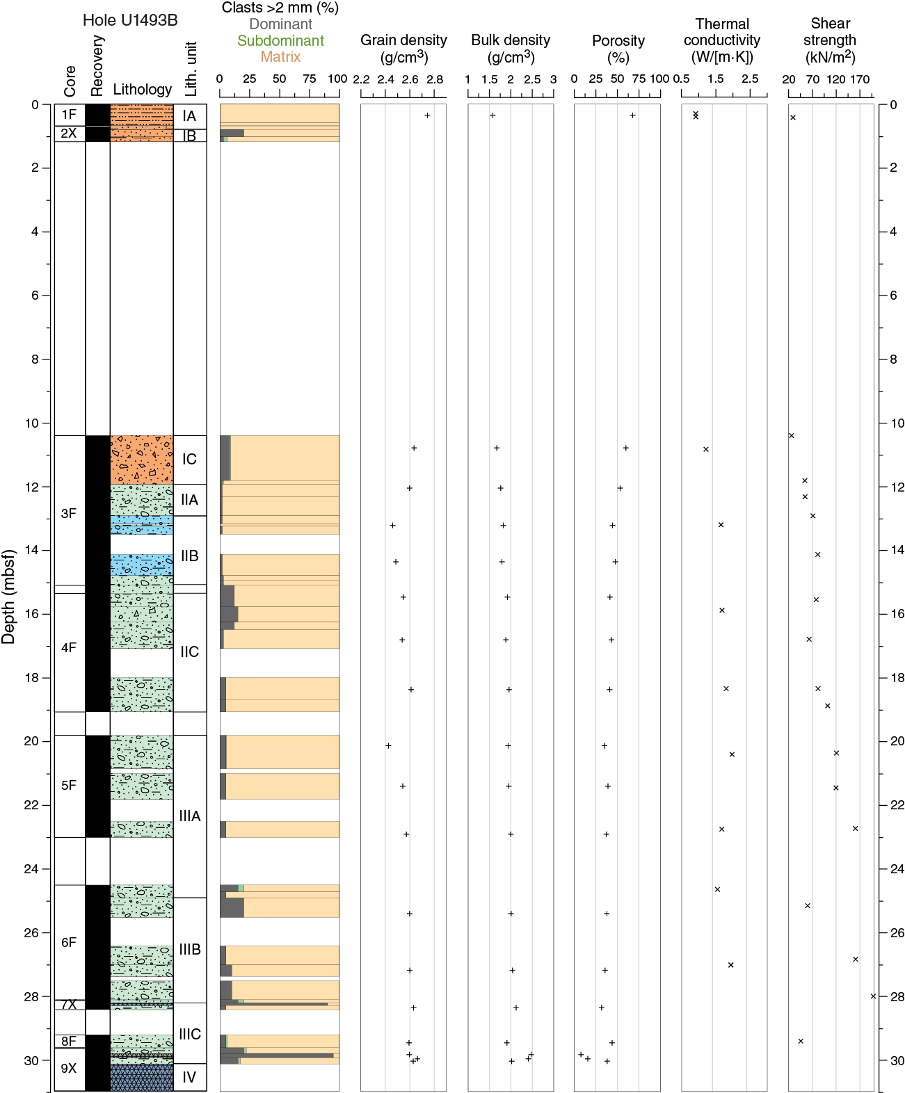
Figure F47. Index property data, thermal conductivity, and shear strength, Hole U1493B.
In Hole U1494A, porosity in Unit I is ~60%, and it decreases through Units II–V from 59% at the top of Unit II to 27% at the bottom of the hole (Figure F48). Void ratio and bulk density follow the porosity trend with depth. Low porosity values (22%–26%) correspond to serpentinized rock clasts in the mud matrix, which are so highly altered that they could be sampled by pushing the MAD cylinder sampler through them. Two such clasts are at 24.97 and 28.57 mbsf. Grain density has a mean value of 2.6 g/cm3 and is rather constant downhole. Drilling disturbance is reflected in the anomalous porosity and bulk density values at 29–32 mbsf in Core 366-U1494A-8F, which was severely affected by coring, with pieces of plastic in the serpentinite muds from the shattered core liner.
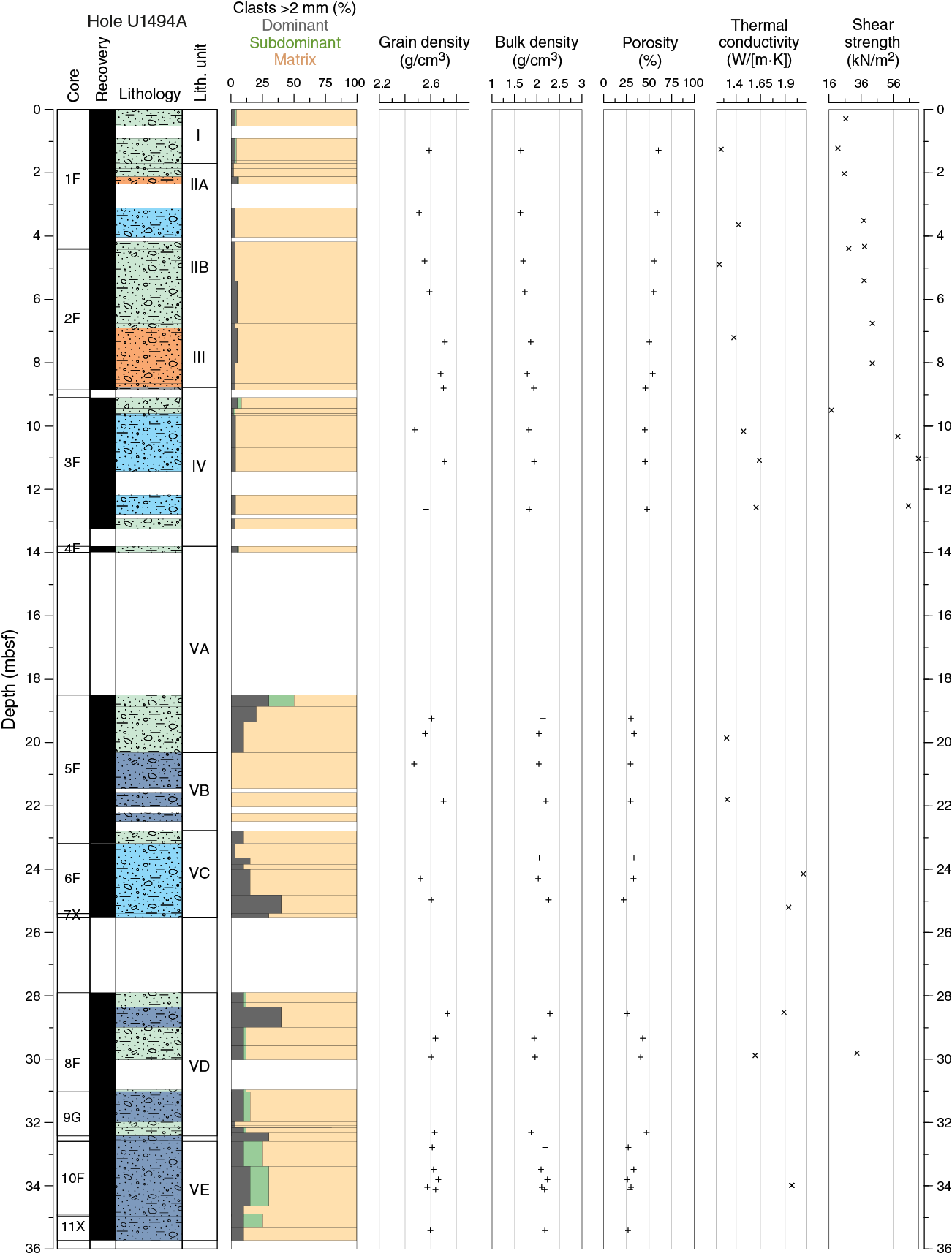
Figure F48. Index property data, thermal conductivity, and shear strength, Hole U1494A.
Holes U1495A and U1495B have average porosity values of ~70% for Unit I pelagic sediment, with a remarkably rapid decreasing trend in Units II and III from 48%–57% at the top of the hole to 35% at the base at only 10 mbsf (Figures F49, F50). Decreasing void ratios and increasing bulk densities follow the porosity–depth trend toward the bottom of the hole. Grain density is rather constant around 2.6 g/cm3.
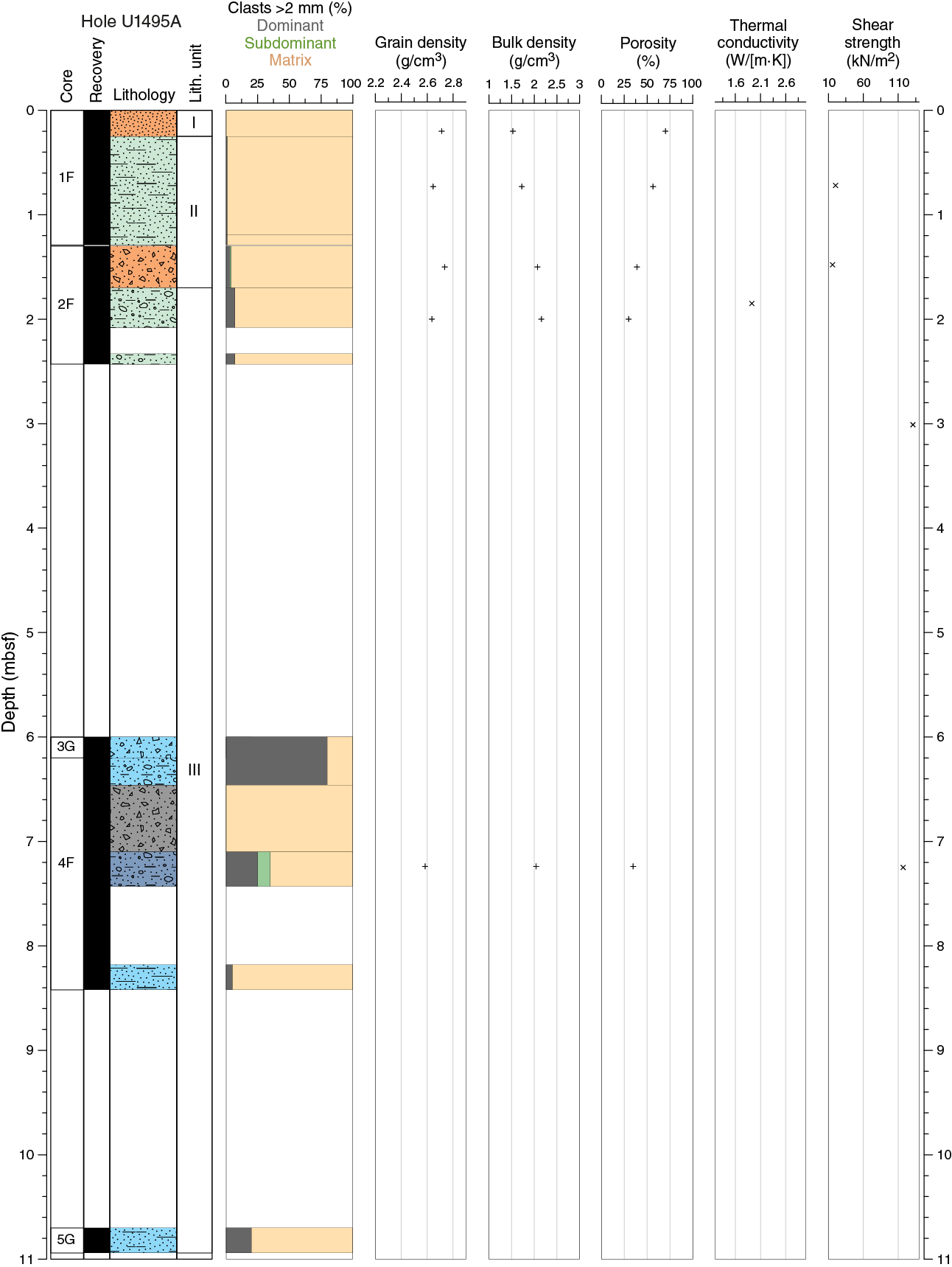
Figure F49. Index property data, thermal conductivity, and shear strength, Hole U1495A.
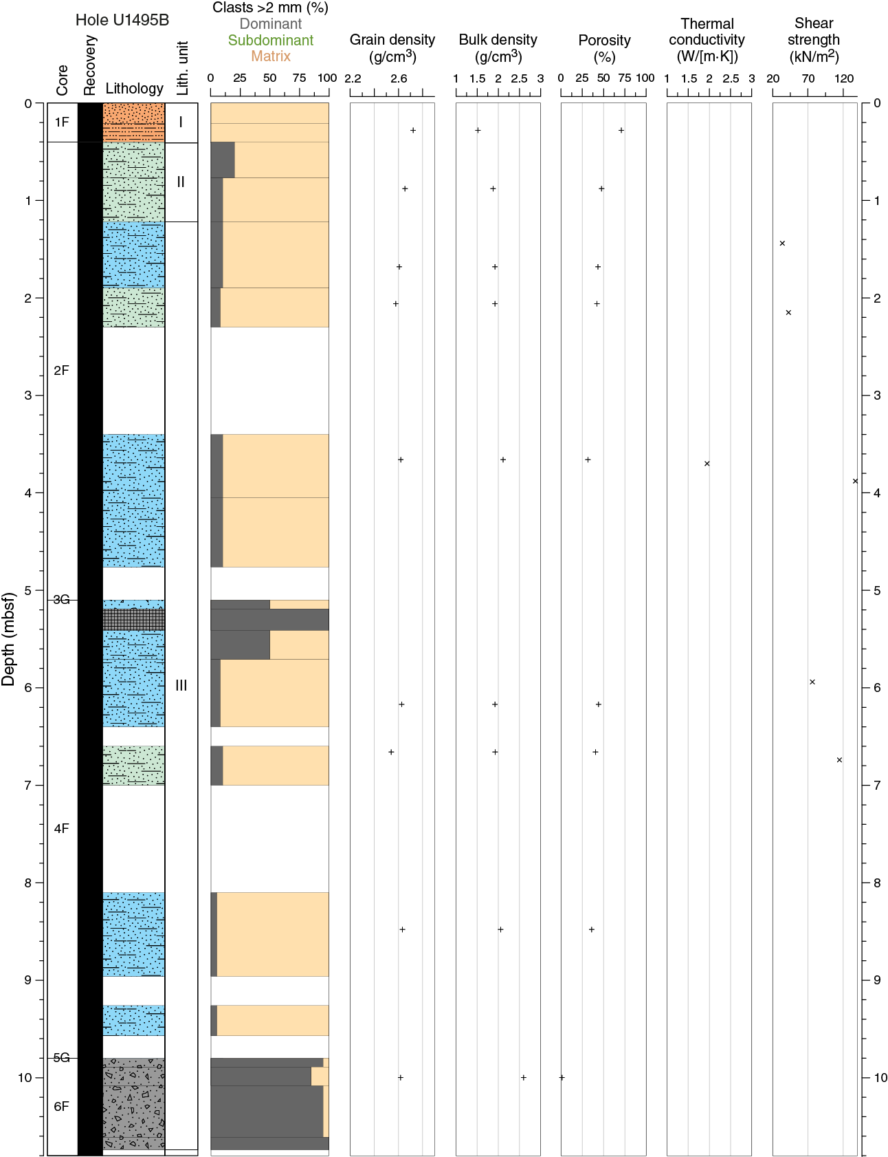
Figure F50. Index property data, thermal conductivity, and shear strength, Hole U1495B.
Thermal conductivity
Hole U1493B thermal conductivity values increase rapidly with depth from 0.9 W/(m·K) near the seafloor to over 1.9 W/(m·K) at 27 mbsf (Figure F47). Unit I values average 1.0, and values from Subunit IIA to the base of the hole average 1.7 W/(m·K). The trend from 0 to 20 mbsf is similar to that observed at the previous lower flank site (Hole U1491B) on the Yinazao mud volcano (see Physical properties in the Site U1491 chapter [Fryer et al., 2018c]). Two values exceeding 1.9 W/(m·K) at 20.4 and 27 mbsf in Subunits IIIA and IIIB, respectively, are higher than previously observed and correspond to increases in GRA bulk density.
Hole U1494A thermal conductivities (Figure F48) increase rapidly with depth from 1.2 W/(m·K) near the seafloor to over 2.0 W/(m·K) at 24 mbsf with an overall average of 1.58 W/(m·K). The trend from 0 to 34 mbsf is only half as steep as that observed in Hole U1493B or at the other lower flank site (Hole U1491B). Two low values (~1.3 W/[m·K]) near 20 mbsf in Subunits VA and VB do not show any clear relationship to other physical properties.
Thermal conductivity measurements were made at only one location each in Holes U1495A and U1495B (Figures F49, F50). Values are about 1.9 and 2.0 W/(m·K), which is near the high end of what was measured during Expedition 366.
Automated vane shear
The undrained shear strength was measured with the automated vane shear in cohesive unconsolidated muds, but no measurements were made on the gravel and in the rock-filled cores recovered at the bottom of each site. The automated vane shear has proven to be an excellent instrument to highlight consolidation trends in the muds, as well as a good proxy, along with the thermal conductivity, to identify core disturbances.
Hole U1493B exhibits a remarkable trend of increasing shear strength from 30 to 198 kN/m2 between 0 and about 28 mbsf (Figure F47) with values that reach the detection threshold for the automated vane shear instrument. Drilling disturbance is highlighted by two spurious points at 25 and 29 mbsf, which measure 60 and 46 kN/m2, respectively.
Hole U1494A also shows a clear increasing trend with depth, in agreement with decreasing porosity and increasing bulk density (Figure F48). Shear strength increases so rapidly in this hole that it was not possible to measure it below 12 mbsf due to the indurated conditions of the serpentinite mud, which impeded the penetration of the vanes. The low values of 18 kN/m2 at 10 mbsf and 30 kN/m2 at 34 mbsf are associated with fall-in in the first sections of the cores.
Shear strength values in Holes U1495A and U1495B increase from 20 to 137 kN/m2 by 3 and 3.8 mbsf, respectively, consistent with the extremely rapid depth changes of the other MAD properties of the mud in this location (Figures F49, F50).
Discussion
The physical property data collected along the transect of Sites U1493, U1494, and U1495 were found to be of good quality to describe the flank deposits of the Asùt Tesoru mud volcano. At these sites, the physical properties usually associated with consolidation change extremely rapidly with depth, including porosity, bulk density, thermal conductivity, and vane shear. The changes are far more rapid than observed in other seafloor sediments (Bekins and Dreiss, 1992). For example, porosity decreases from 60% to 30% in just 20 m of burial at Sites U1493 and U1494 (Figures F47, F48). At Site U1495, a decrease of 30% occurs with less than 4 m burial. At the bottom of the holes at these flank sites, serpentinite mud physical properties show higher values than those observed at different seamount summits of the Mariana forearc (see Physical properties in the Site U1492 chapter and Physical properties in the Site U1496 chapter [Fryer et al., 2018d, 2018e]; Conical Seamount, ODP Leg 125 [Fryer, Pearce, Stokking, et al., 1992]). These values are similar along the three-site transect. Bulk density, P-wave velocity, porosity, and thermal conductivity are 2.2–2.3 g/cm3, ~1900 m/s, ~30%, and ~2 W/(m·K), respectively. In comparison to summit deposits, such rapid changes with depth are unlikely to be related to compaction only. The top pelagic deposits, particularly well highlighted with NGR measurements, indicate that fluid and serpentinite mudflows are no longer active on the southern flank of this seamount. Therefore, low-temperature diagenetic processes or gravitational destabilization and sliding along the flanks may be important in explaining the differences with the deposits of the mud volcano’s active summits.
Downhole measurements
Temperature data were collected at only one of the three flank sites on Asùt Tesoru Seamount. A single APCT-3 measurement was attempted while taking Core 366-U1493B-5F at 24.5 mbsf. The temperature record was of questionable quality, and the deployment notes indicate the core barrel advanced only a partial stroke of 3.6 m. The data exhibit two frictional heating peaks during the 10 min deployment (Figure F51). The first peak corresponds to the initial deployment time, and the second peak is 400 s later. The temperature rise at the second peak was over 5°C, suggesting frictional heating and good penetration of the tool. The temperature record after the second peak provided a smooth record with a continuous decline, but extra frictional heating violates the assumptions of the TP-Fit model. For these reasons, both the first and the second peak were selected for analysis with the TP-Fit software. The starting pick for the first peak was set 105 s after the first peak, and the ending was set at 267 s, providing 2.7 min for analysis. The estimated temperature was 2.25°C using the full window. The starting pick for the second peak was set shortly after the second peak, and the ending was set as late as possible, providing 5.4 min for analysis. The estimated temperature was 2.57°C using the full window and 2.51°C using the final third of the data window (Table T15), which is the preferred value (see Downhole measurements in Expedition 366 methods chapter [Fryer et al., 2018a]). During the deployment, bottom water temperature was recorded for an exceptionally long period of 140 min. The recorded temperature during this period was stable at 1.73° ± 0.025°C.

Figure F51. APCT-3 temperature measurements.
Table T15. Temperature data, Hole U1493B. Download table in CSV format.
Data for the seafloor and two downhole temperature estimates are plotted in Figure F52. Using these two values yields a gradient of 26.5°C/km for this site. Multiplying this gradient by the average measured thermal conductivity of 1.53 W/(m·K) results in an estimated heat flow of 40.0 mW/m2.

Figure F52. APCT-3 formation and bottom seawater temperatures.
Discussion
Calculated thermal gradients and heat flow at Site U1493 must be considered tentative due to the poor quality of the single record and the shallow measurement depth. To provide regional context, we compared our results to nearby calculations of heat flow. During DSDP Leg 60, Uyeda and Horai (1982) estimated thermal gradient and heat flow values in Holes 458A and 459B, located 23 and 26 km from Hole U1493B, respectively. At both sites, they used the Tokyo T-probe, which was pushed ~60 cm into the formation at the base of the hole and held there for 58 min. At Site 458, two deployments gave a bottom water temperature of 1.9°C and an estimated gradient between 16.1 and 34.2°C/km, resulting in an average heat flow estimate of 25 mW/m2. At Site 459, a single deployment yielded a bottom water temperature of 1.65°C and questionable temperature data. In addition, two temperature logs conducted 2.4 and 20 h after fluid circulation ended were extrapolated to determine undisturbed formation temperatures. Taken together, the two methods yield a temperature gradient of 29°C/km and an estimated heat flow of 30 mW/m2. Comparison of these data to Hole U1493B gives good correspondence with the gradient but 25% lower heat flow. The difference is due to the lower average thermal conductivity of ~1 W/(m·K) for the pelagic sediments, which is 33% lower than the average value for Hole U1493B.
Paleomagnetism
Determination of NRM was generally performed on every archive half from Holes U1493B, U1494A, U1495A, and U1495B at 5 cm intervals after 0, 5, 10, 15, and 20 mT alternating field (AF) demagnetization using the shipboard superconducting rock magnetometer (SRM). Measurements were preferentially carried out on sections where the serpentinite mud was not sandy, watery, or heavily disturbed by the coring process. A total of 40 representative discrete samples were collected, and their NRMs were measured after 0–30 mT AF demagnetization.
Results
We analyzed NRM inclinations and declinations on both discrete samples (Figure F53) and section halves, mainly in the layers of ash-bearing pelagic sediments, using principal component analyses (PCA). PCA of demagnetization data and the results at the 20 mT demagnetization step from discrete samples and the section halves are generally characterized by strong vertical overprint, likely due to the drill string and perhaps also due to subvertical shearing in cores affected by flow-in disturbance.
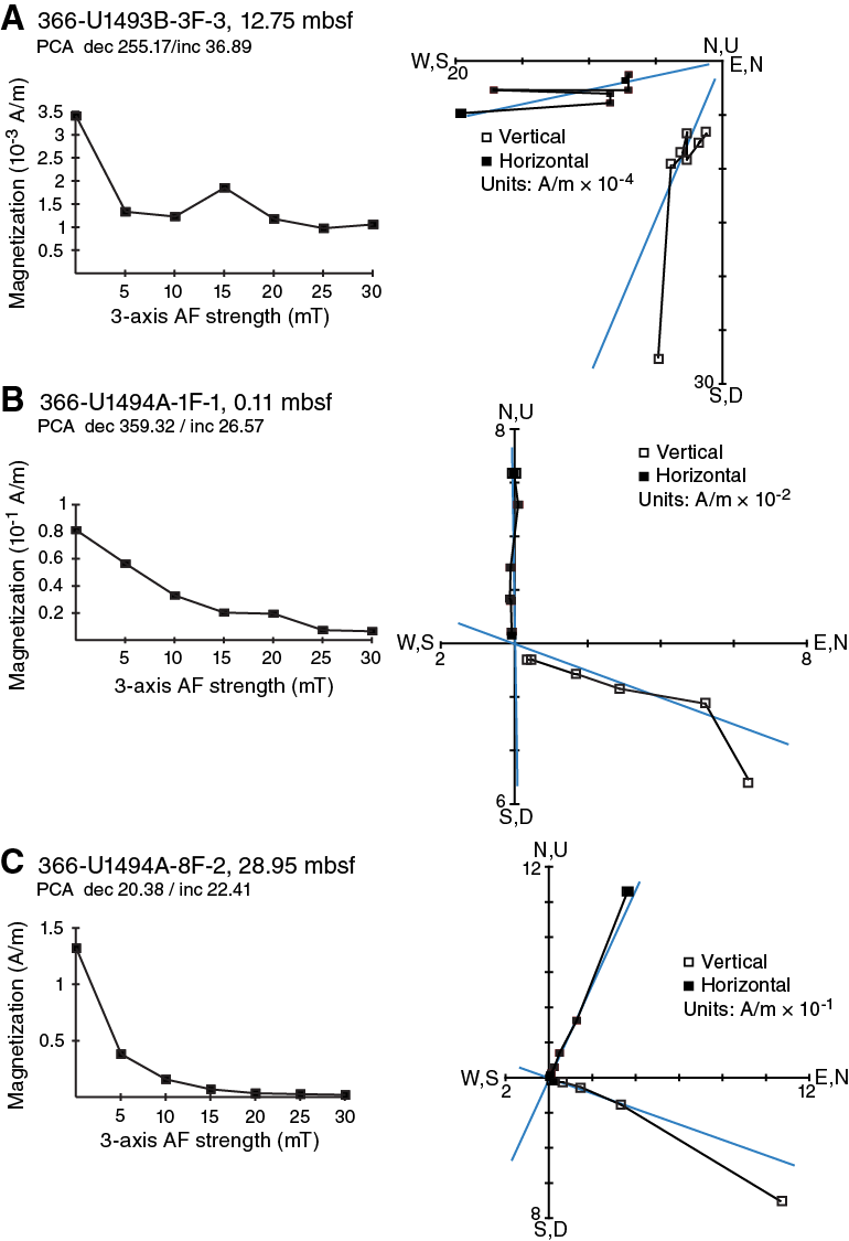
Figure F53. NRM decay and AF demagnetization vector.
Hole U1493B section halves show an increasing trend with depth in the intensity values after 20 mT AF demagnetization. Relatively higher values of ~4.6 × 10⁻² A/m occur, especially below 18 mbsf, corresponding to Subunits IIIA–IIIC, which consist of blue-green serpentinite pebbly mud with ultramafic rock clasts (Figure F54). Similarly, Hole U1494A has an increasing trend in NRM intensity near the bottom (Figure F55). Hole U1495A has an average intensity value of 2.1 × 10⁻² A/m, with the lowest value of 8.0 × 10⁻³ A/m in the serpentinite mud with sand of Unit II (Figure F56). In Hole U1495B, intensity varies, ranging from 5.6 × 10⁻³ to 3.5 × 10⁻² A/m, and does not relate to the lithostratigraphic units (Figure F57). The increasing trend in NRM intensities with depth generally corresponds to increasing magnetic susceptibility values (see Physical properties), indicating greater concentration of ferromagnetic minerals like magnetite with depth.
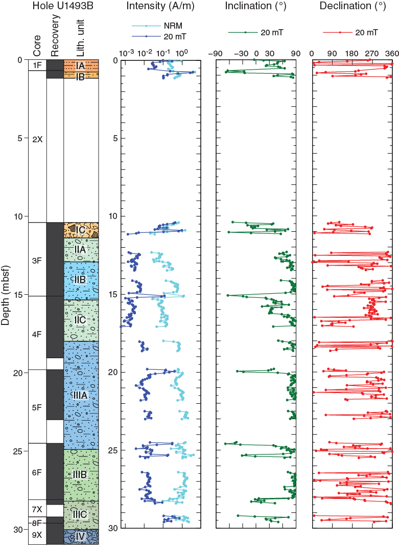
Figure F54. NRM intensity, inclination, and declination, Hole U1493B.
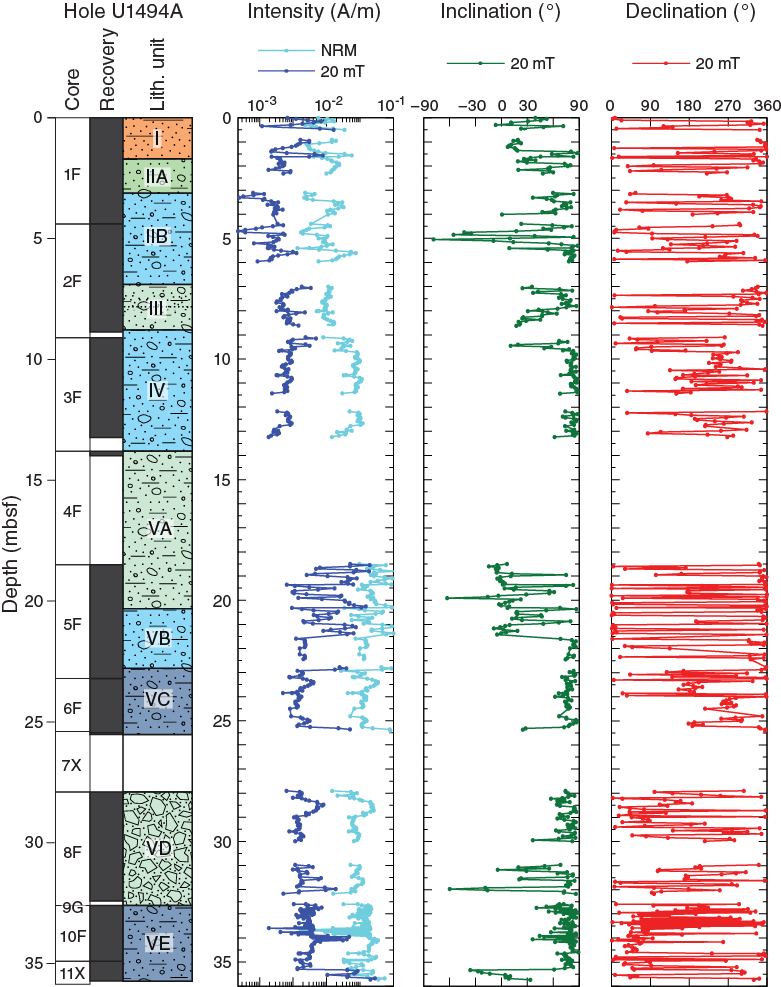
Figure F55. NRM intensity, inclination, and declination, Hole U1494A.
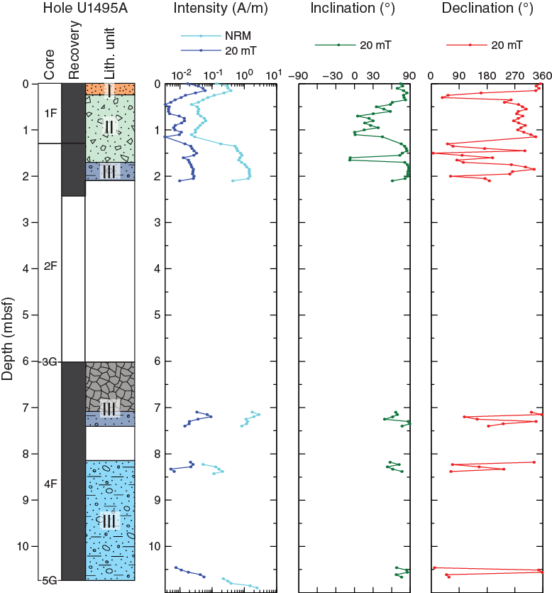
Figure F56. NRM intensity, inclination, and declination, Hole U1495A.
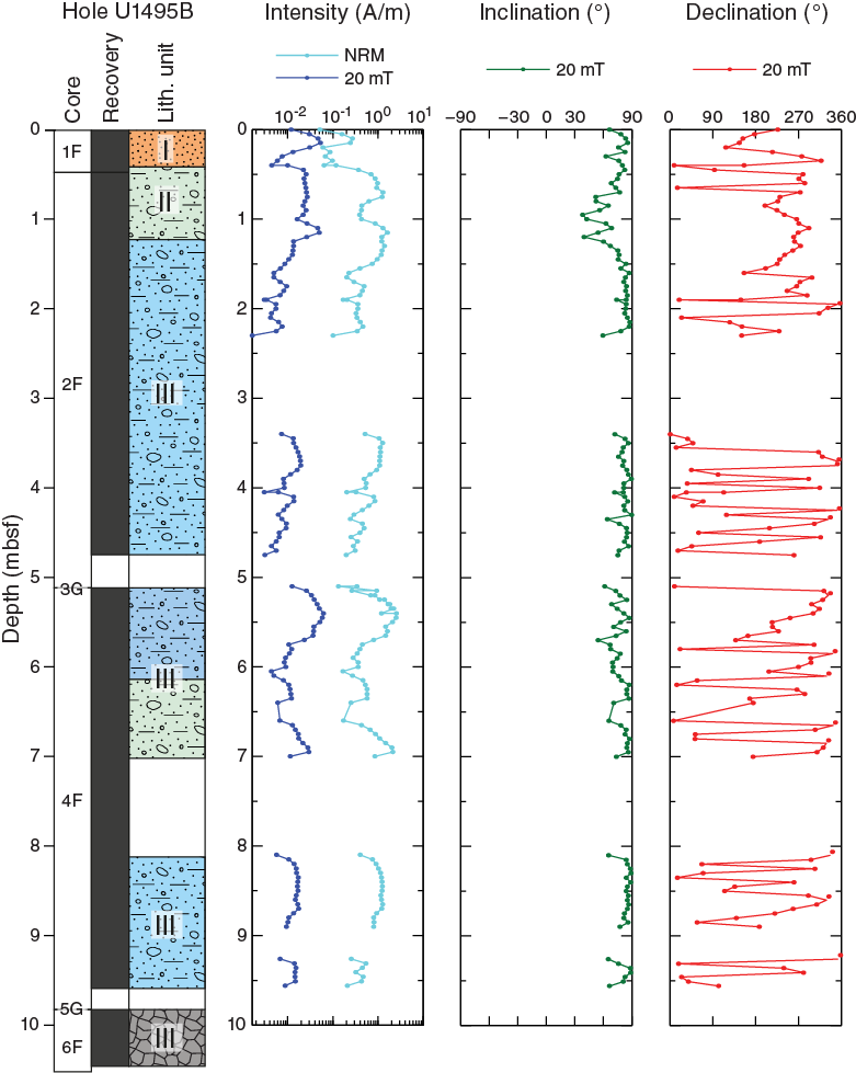
Figure F57. NRM intensity, inclination, and declination, Hole U1495B.
References
Bekins, B.A., and Dreiss, S.J., 1992. A simplified analysis of parameters controlling dewatering in accretionary prisms. Earth and Planetary Science Letters, 10(3–4)275–287. https://doi.org/10.1016/0012-821X(92)90092-A
Desprairies, A., 1982. Authigenic minerals in volcanogenic sediments cored during Deep Sea Drilling Project Leg 60. In Hussong, D.M., Uyeda, S., et al., Initial Reports of the Deep Sea Drilling Project, 60: Washington, DC (U.S. Government Printing Office), 455–466. https://doi.org/10.2973/dsdp.proc.60.120.1982
Eglinton, T.I., and Repeta, D.J., 2014. Organic matter in the contemporary ocean. In Mottl, M.J., and Elderfield, H. (Eds.), Treatise on Geochemistry (2nd Edition) (Volume 8): The Oceans and Marine Geochemistry. Holland, H.D., and Turekian, K.K. (Series Eds.): Oxford, United Kingdom (Elsevier), 151–189. https://doi.org/10.1016/B978-0-08-095975-7.00606-9
Fryer, P., Pearce, J.A., Stokking, L.B., et al., 1992. Proceedings of the Ocean Drilling Program, Scientific Results, 125: College Station, TX (Ocean Drilling Program). https://doi.org/10.2973/odp.proc.sr.125.1992
Fryer, P., Wheat, C.G., Williams, T., Albers, E., Bekins, B., Debret, B.P.R., Deng, J., Dong, Y., Eickenbusch, P., Frery, E.A., Ichiyama, Y., Johnson, K., Johnston, R.M., Kevorkian, R.T., Kurz, W., Magalhaes, V., Mantovanelli, S.S., Menapace, W., Menzies, C.D., Michibayashi, K., Moyer, C.L., Mullane, K.K., Park, J.-W., Price, R.E., Ryan, J.G., Shervais, J.W., Sissmann, O.J., Suzuki, S., Takai, K., Walter, B., and Zhang, R., 2018a. Expedition 366 methods. In Fryer, P., Wheat, C.G., Williams, T., and the Expedition 366 Scientists, Mariana Convergent Margin and South Chamorro Seamount. Proceedings of the International Ocean Discovery Program, 366: College Station, TX (International Ocean Discovery Program). https://doi.org/10.14379/iodp.proc.366.102.2018
Fryer, P., Wheat, C.G., Williams, T., Albers, E., Bekins, B., Debret, B.P.R., Deng, J., Dong, Y., Eickenbusch, P., Frery, E.A., Ichiyama, Y., Johnson, K., Johnston, R.M., Kevorkian, R.T., Kurz, W., Magalhaes, V., Mantovanelli, S.S., Menapace, W., Menzies, C.D., Michibayashi, K., Moyer, C.L., Mullane, K.K., Park, J.-W., Price, R.E., Ryan, J.G., Shervais, J.W., Sissmann, O.J., Suzuki, S., Takai, K., Walter, B., and Zhang, R., 2018b. Expedition 366 summary. In Fryer, P., Wheat, C.G., Williams, T., and the Expedition 366 Scientists, Mariana Convergent Margin and South Chamorro Seamount. Proceedings of the International Ocean Discovery Program, 366: College Station, TX (International Ocean Discovery Program). https://doi.org/10.14379/iodp.proc.366.101.2018
Fryer, P., Wheat, C.G., Williams, T., Albers, E., Bekins, B., Debret, B.P.R., Deng, J., Dong, Y., Eickenbusch, P., Frery, E.A., Ichiyama, Y., Johnson, K., Johnston, R.M., Kevorkian, R.T., Kurz, W., Magalhaes, V., Mantovanelli, S.S., Menapace, W., Menzies, C.D., Michibayashi, K., Moyer, C.L., Mullane, K.K., Park, J.-W., Price, R.E., Ryan, J.G., Shervais, J.W., Sissmann, O.J., Suzuki, S., Takai, K., Walter, B., and Zhang, R., 2018c. Site U1491. In Fryer, P., Wheat, C.G., Williams, T., and the Expedition 366 Scientists, Mariana Convergent Margin and South Chamorro Seamount. Proceedings of the International Ocean Discovery Program, 366: College Station, TX (International Ocean Discovery Program). https://doi.org/10.14379/iodp.proc.366.104.2018
Fryer, P., Wheat, C.G., Williams, T., Albers, E., Bekins, B., Debret, B.P.R., Deng, J., Dong, Y., Eickenbusch, P., Frery, E.A., Ichiyama, Y., Johnson, K., Johnston, R.M., Kevorkian, R.T., Kurz, W., Magalhaes, V., Mantovanelli, S.S., Menapace, W., Menzies, C.D., Michibayashi, K., Moyer, C.L., Mullane, K.K., Park, J.-W., Price, R.E., Ryan, J.G., Shervais, J.W., Sissmann, O.J., Suzuki, S., Takai, K., Walter, B., and Zhang, R., 2018d. Site U1492. In Fryer, P., Wheat, C.G., Williams, T., and the Expedition 366 Scientists, Mariana Convergent Margin and South Chamorro Seamount. Proceedings of the International Ocean Discovery Program, 366: College Station, TX (International Ocean Discovery Program). https://doi.org/10.14379/iodp.proc.366.105.2018
Fryer, P., Wheat, C.G., Williams, T., Albers, E., Bekins, B., Debret, B.P.R., Deng, J., Dong, Y., Eickenbusch, P., Frery, E.A., Ichiyama, Y., Johnson, K., Johnston, R.M., Kevorkian, R.T., Kurz, W., Magalhaes, V., Mantovanelli, S.S., Menapace, W., Menzies, C.D., Michibayashi, K., Moyer, C.L., Mullane, K.K., Park, J.-W., Price, R.E., Ryan, J.G., Shervais, J.W., Sissmann, O.J., Suzuki, S., Takai, K., Walter, B., and Zhang, R., 2018e. Site U1496. In Fryer, P., Wheat, C.G., Williams, T., and the Expedition 366 Scientists, Mariana Convergent Margin and South Chamorro Seamount. Proceedings of the International Ocean Discovery Program, 366: College Station, TX (International Ocean Discovery Program). https://doi.org/10.14379/iodp.proc.366.107.2018
Hulme, S.M., Wheat, C.G., Fryer, P., and Mottl, M.J., 2010. Pore water chemistry of the Mariana serpentinite mud volcanoes: a window to the seismogenic zone. Geochemistry, Geophysics, Geosystems, 11(1):Q01X09. http://dx.doi.org/10.1029/2009GC002674
Johnston, R.M., Ryan, J.G., and the Expedition 366 Scientists, 2018. pXRF and ICP-AES characterization of shipboard rocks and sediments: protocols and strategies. In Fryer, P., Wheat, C.G., Williams, T., and the Expedition 366 Scientists, Mariana Convergent Margin and South Chamorro Seamount. Proceedings of the International Ocean Discovery Program, 366: College Station, TX (International Ocean Discovery Program). https://doi.org/10.14379/iodp.proc.366.110.2018
Mottl, M.J., Komor, S.C., Fryer, P., and Moyer, C.L., 2003. Deep-slab fluids fuel extremophilic Archaea on a Mariana forearc serpentinite mud volcano: Ocean Drilling Program Leg 195. Geochemistry, Geophysics, Geosystems, 4:9009. http://dx.doi.org/10.1029/2003GC000588
Mottl, M.J., Wheat, C.G., Fryer, P., Gharib, J., and Martin, J.B., 2004. Chemistry of springs across the Mariana forearc shows progressive devolatilization of the subducting plate. Geochimica et Cosmochimica Acta, 68(23):4915–4933. http://dx.doi.org/10.1016/j.gca.2004.05.037
Oakley, A.J., Taylor, B., Fryer, P., Moore, G.F., Goodliffe, A.M., and Morgan, J.K., 2007. Emplacement, growth, and gravitational deformation of serpentinite seamounts on the Mariana forearc. Geophysical Journal International, 170(2):615–634. http://dx.doi.org/10.1111/j.1365-246X.2007.03451.x
Oakley, A.J., Taylor, B., and Moore, G.F., 2008. Pacific plate subduction beneath the central Mariana and Izu-Bonin fore arcs: new insights from an old margin. Geochemistry, Geophysics, Geosystems, 9(6):Q06003. https://doi.org/10.1029/2007GC001820
Phipps, S.P., and Ballotti, D., 1992. Rheology of serpentinite muds in the Mariana-Izu-Bonin forearc. In Fryer, P., Pearce, J.A., Stokking, L.B., et al., Proceedings of the Ocean Drilling Program, Scientific Results, 125: College Station, TX (Ocean Drilling Program), 363–372. http://dx.doi.org/10.2973/odp.proc.sr.125.154.1992
Savov, I.P., Ryan, J.G., D’Antonio, M., Kelley, K., and Mattie, P., 2005. Geochemistry of serpentinized peridotites from the Mariana Forearc Conical Seamount, ODP Leg 125: implications for the elemental recycling at subduction zones. Geochemistry, Geophysics, Geosystems, 6(4):Q04J15. https://doi.org/10.1029/2004GC000777
Uyeda, S., and Horai, K., 1982. Heat flow measurements on Deep Sea Drilling Project Leg 60. In Hussong, D.M., Uyeda, S., et al., Initial Reports of the Deep Sea Drilling Project, 60: Washington, DC (U.S. Government Printing Office), 789–800. https://doi.org/10.2973/dsdp.proc.60.146.1982
1 Fryer, P., Wheat, C.G., Williams, T., Albers, E., Bekins, B., Debret, B.P.R., Deng, J., Dong, Y., Eickenbusch, P., Frery, E.A., Ichiyama, Y., Johnson, K., Johnston, R.M., Kevorkian, R.T., Kurz, W., Magalhaes, V., Mantovanelli, S.S., Menapace, W., Menzies, C.D., Michibayashi, K., Moyer, C.L., Mullane, K.K., Park, J.-W., Price, R.E., Ryan, J.G., Shervais, J.W., Sissmann, O.J., Suzuki, S., Takai, K., Walter, B., and Zhang, R., 2018. Sites U1493, U1494, and U1495. In Fryer, P., Wheat, C.G., Williams, T., and the Expedition 366 Scientists, Mariana Convergent Margin and South Chamorro Seamount. Proceedings of the International Ocean Discovery Program, 366: College Station, TX (International Ocean Discovery Program). https://doi.org/10.14379/iodp.proc.366.106.2018
2 Expedition 366 Scientists’ addresses.
This work is distributed under the Creative Commons Attribution 4.0 International (CC BY 4.0) license. 